Raster (or bitmap) images are generally what you think about when thinking of images.
These are the types of images that are produced when scanning or photographing an object.
Raster images are compiled using pixels, or tiny dots,
containing unique color and tonal information that come together to create the image. Raster images use bit maps to store information.
The common software for RASTER graphics are:
*GIMP
*Photoshop
*Microsoft Paint
*Paint
*Krita
File extensions: .BMP, .TIF, .GIF, .JPG
By using the paint some screenshoot are as follow;
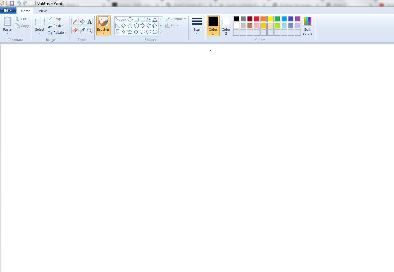
Different tools in paint.
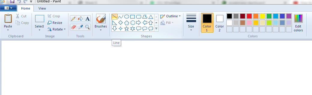
Openning and selecting line command
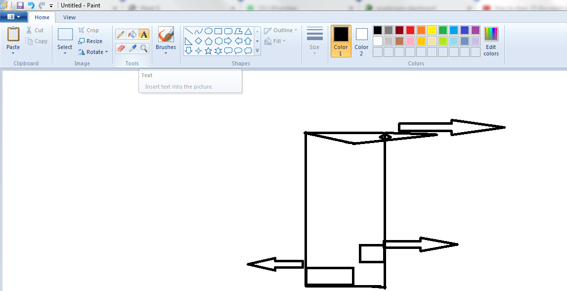
using of the arrow and text command
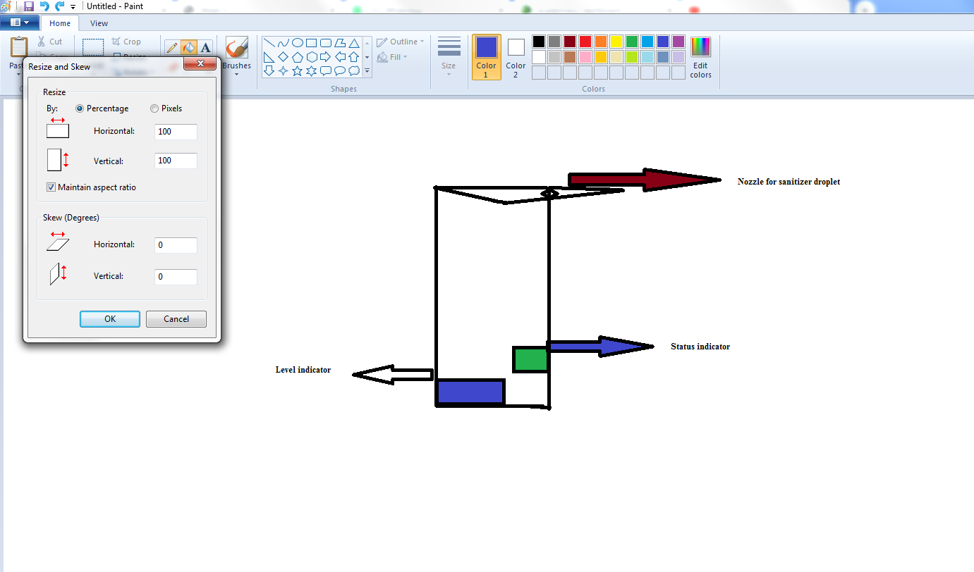
Using the brush command for colouring and resize for changing th size.
Rough sketch of my final project in paint
VECTOR
Vector is an object that has both a magnitude and a direction. Geometrically,
we can picture a vector as a directed line segment. Vector images are not based on pixel patterns. In Vector use mathematical
formulas to draw lines and curves that can be combined to create an image from geometric objects such as circles and polygons.
Vector images are edited by manipulating the lines and curves that make up the image using a program such as Adobe Illustrator.
The common software for RASTER graphics are:
Inkscape
*Scribus
*loDraw
*Illustrator
*CorelDRAW
USing Inkscape as a vector. Before this I was not ever use this software it was new to me my instructor guide me and share some links to
watch more about the Inkscape:
Inkscape
Inkscape is a free and open-source vector graphics editor; it can be used to create or edit vector graphics such as illustrations, diagrams, line arts, charts, logos and complex paintings. Inkscape's primary vector graphics format is Scalable Vector Graphics (SVG); however, many other formats can be imported and exported.Inkscape can render primitive vector shapes (e.g. rectangles, ellipses, polygons, arcs, spirals, stars and 3D boxes) and text. These objects may be filled with solid colors, patterns, radial or linear color gradients and their borders may be stroked, both with adjustable transparency. Embedding and optional tracing of raster graphics is also supported, enabling the editor to create vector graphics from photos and other raster sources. Created shapes can be further manipulated with transformations, such as moving, rotating, scaling and skewing. By using the Inkscape I try to sketch the picture to be on the wall of my project;
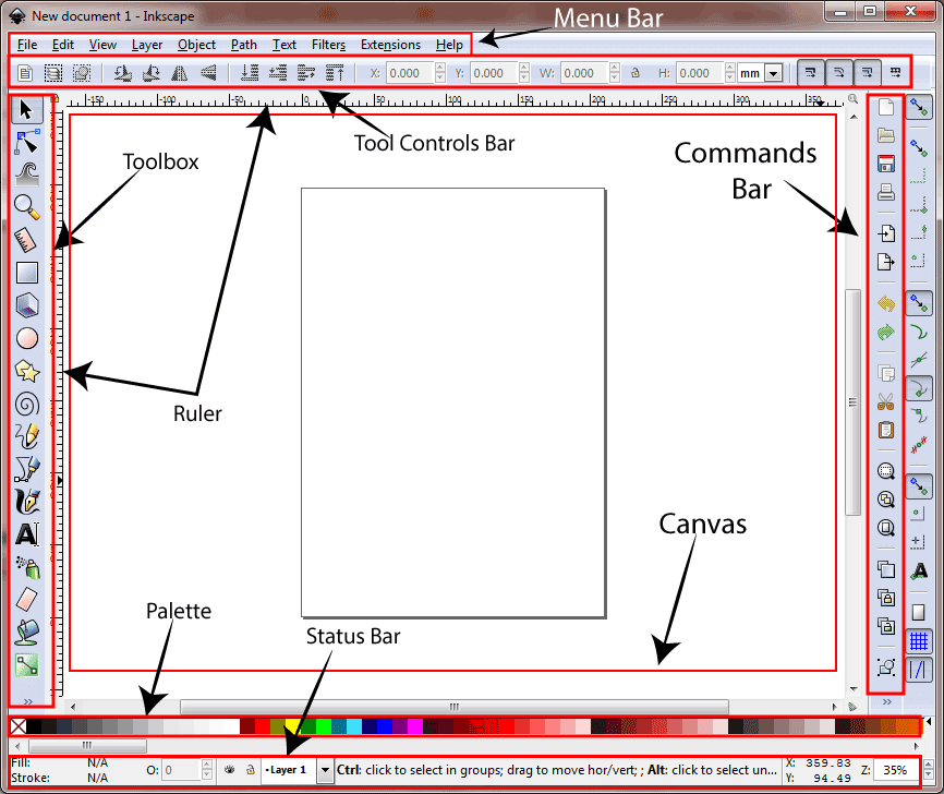
figure shows diffrent tools in Inkscape.
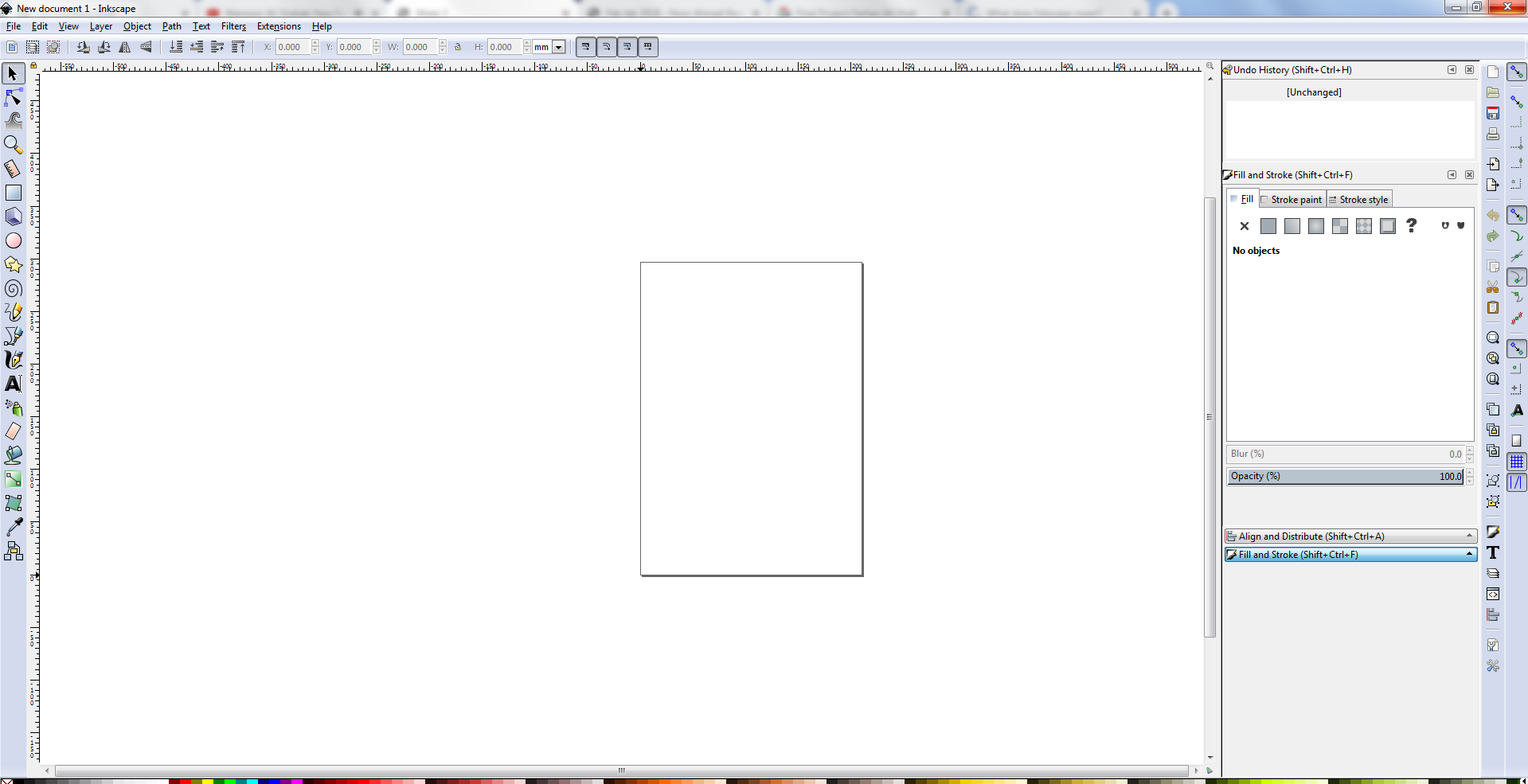
After opening the inkscape I drag the image
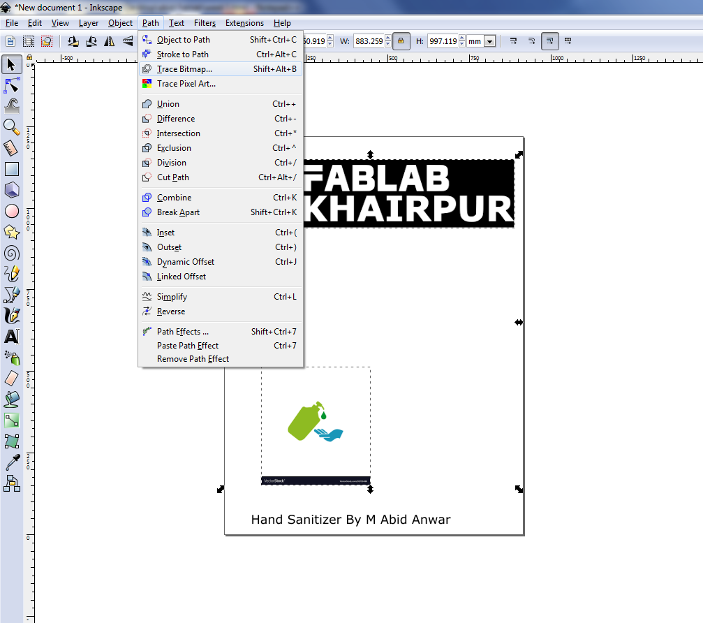
Writing my name and Trace bitmaping of the picture.
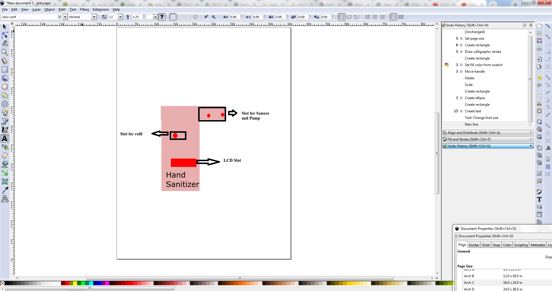
Design ketch of project at Inkscape.
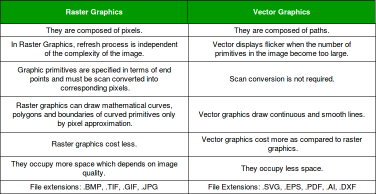
Differences between Vector and Raster graphics
The main difference between vector and raster graphics is that raster graphics are composed of pixels, while vector graphics are composed of paths. A raster graphic, such as a gif or jpeg, is an array of pixels of various colors, which together form an image.
3D DESIGING
There are two types of software or work flow of 3D designing.
1. Non Parametric 3D softwares.
2. Parametric 3D software.
There are also software in which we can work on parametric as well as non parametric 3D designing.
NON-PARAMETRIC 3D DESIGNING
Nonparametric modelling involves a direct approach to building 3D models without having to work with provided parameters. Therefore, you will not be required to start with a 2D draft and produce a 3D model by adding different entities. This means you directly model your ideas without working with pre-set constraints. That is also why nonparametric modelling is also known as direct modelling.
SKETCHUP
SketchUp is a 3D modeling computer program for a wide range of drawing applications such as architectural,
interior design, landscape architecture, Civil and mechanical engineering, film and video game design.
I Try to design my final project at google Sketchup as:
PARAMETRIC 3D DESIGNING
Parametric design is a process based on algorithmic thinking that enables the expression of parameters and rules that,
together, define, encode and clarify the relationship between design intent and design response by using the parametic we can make
change the paremter accordingly
. There are many parametric software but I like to use Solid works.
first I open the Solid work software and select the parts.
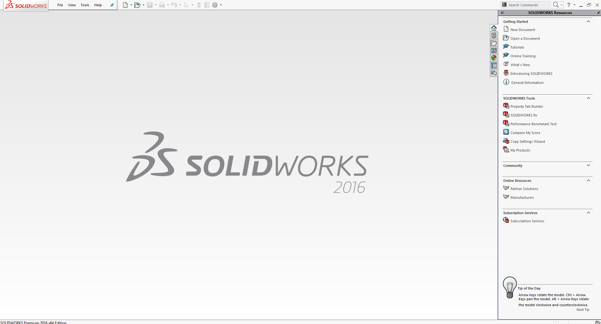
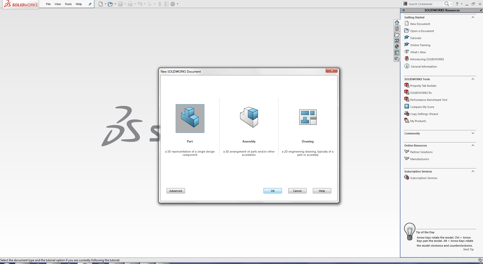
fig:Screen shot of opening and selecting the parts in the solid work.
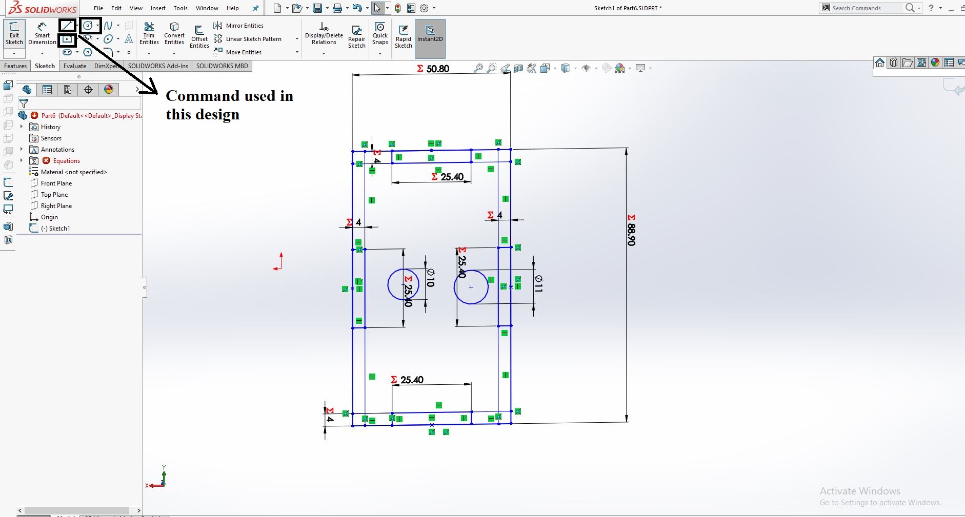
As I am going to design the sketch for my final project as in this there will be four side of the box one side will be different from the rest of three as I have to add LCD, Sensor and Sensor on the front front side so
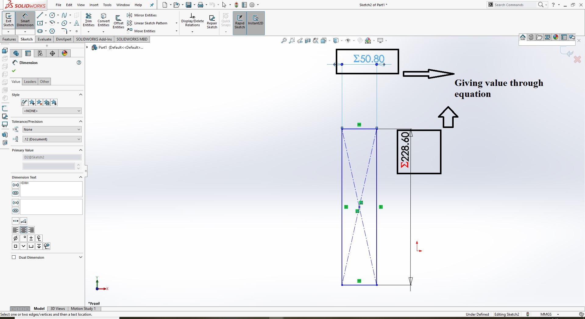
I Started by using the givenig equation as I have to use it further in other parts of my project as:
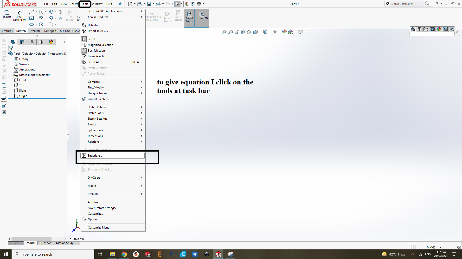

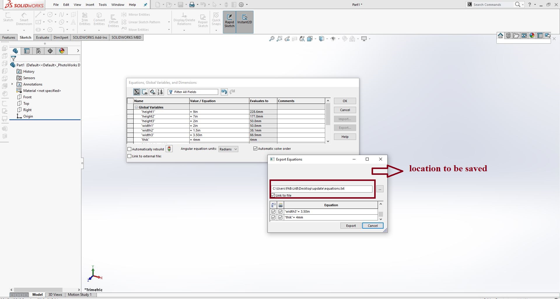
Giving the equation and exporting for using in other parts.
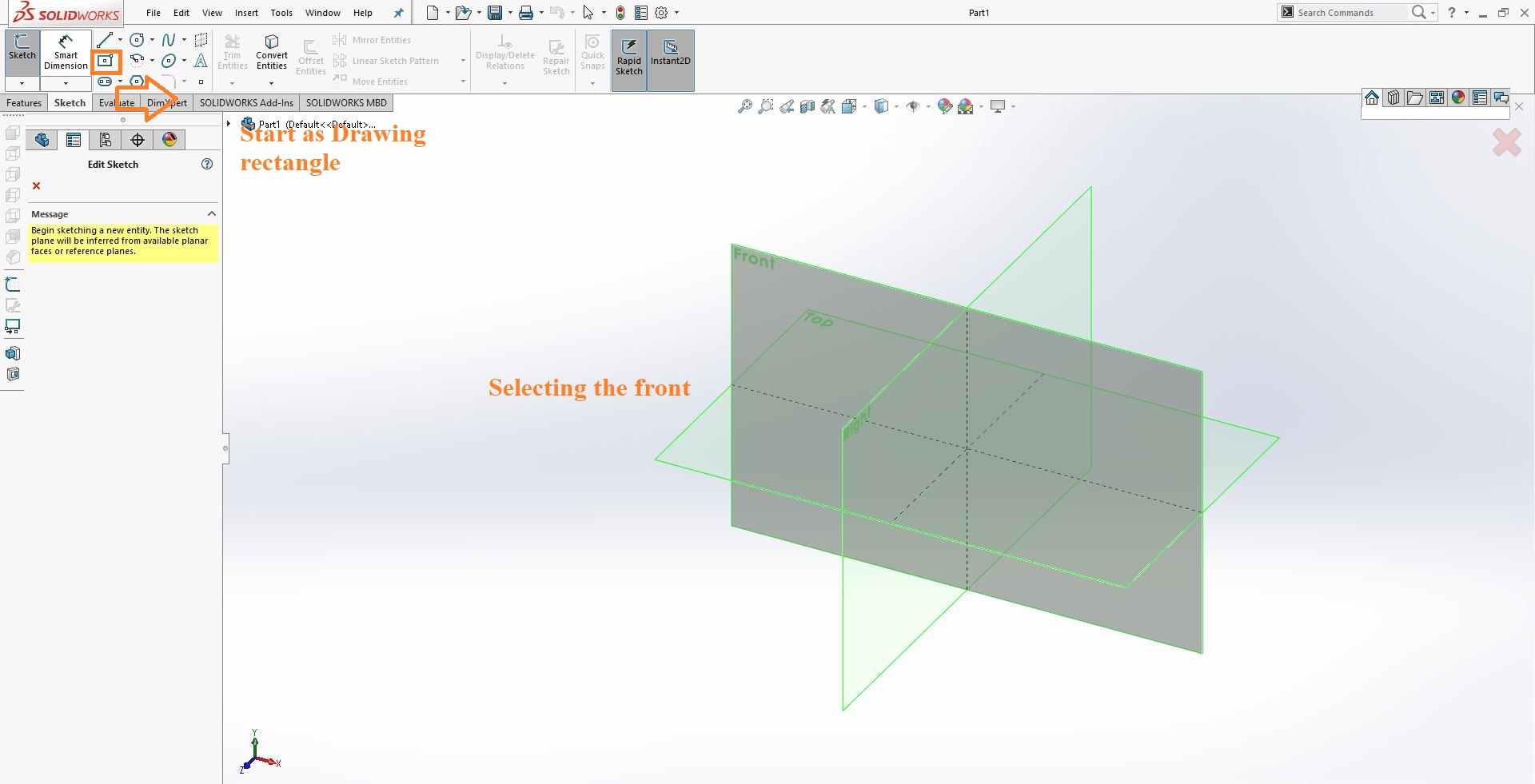
Making the sides of the walls
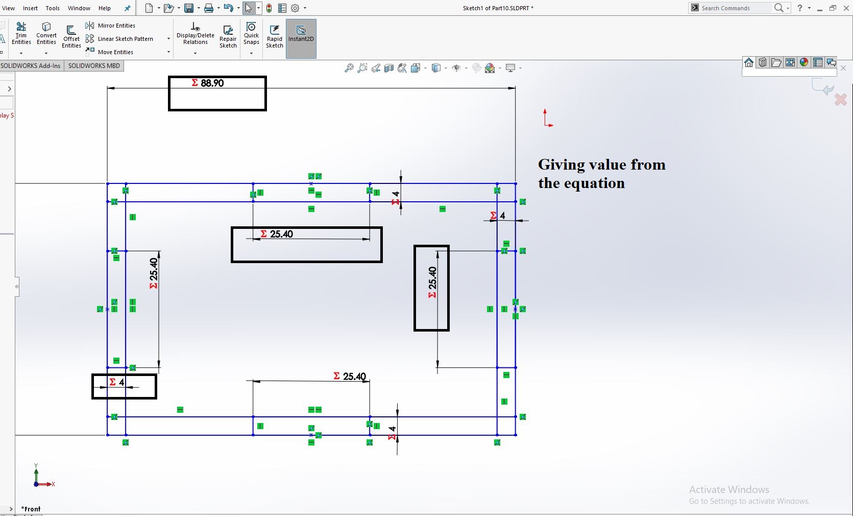
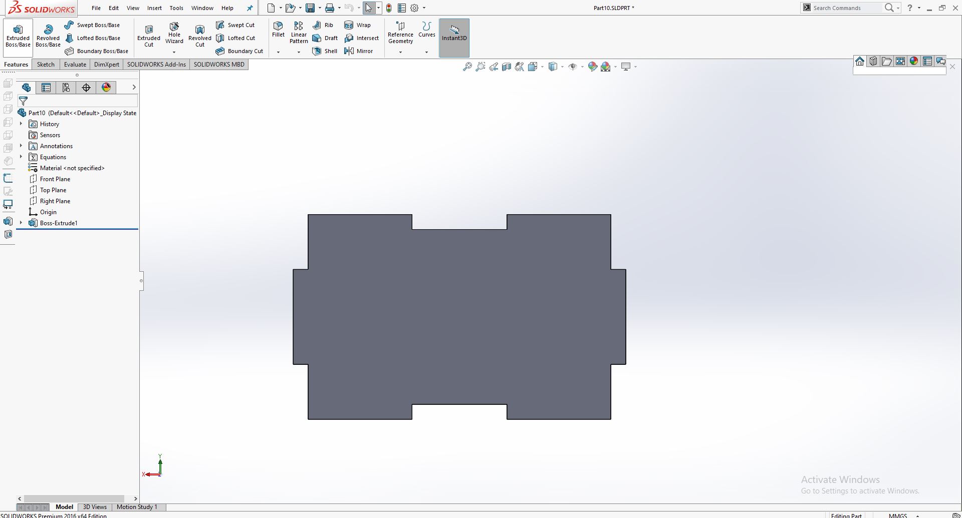
After that I draw the rectangle command and give the value through the equations and use different command as , Extude Base, Cut for the wall as :
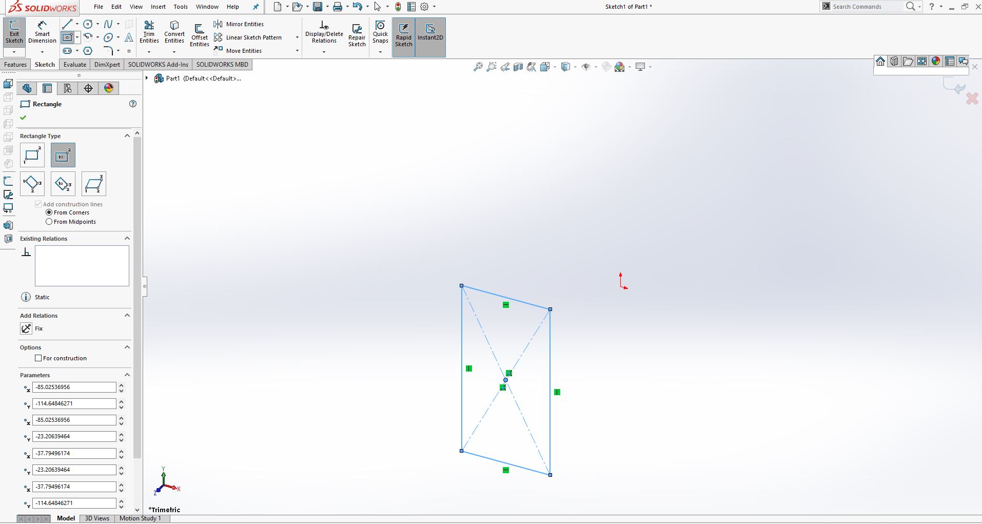
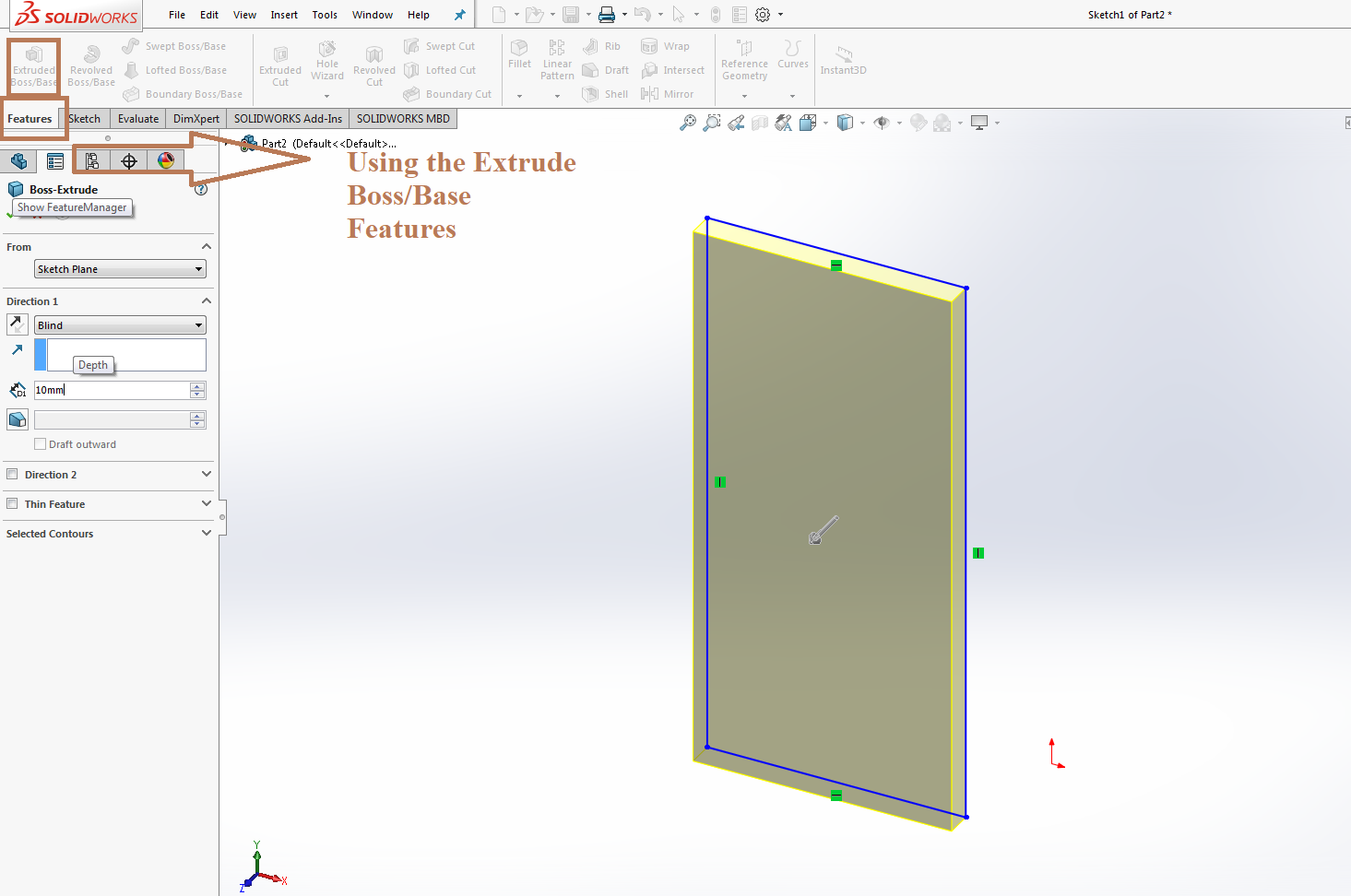

Desiging the parts.
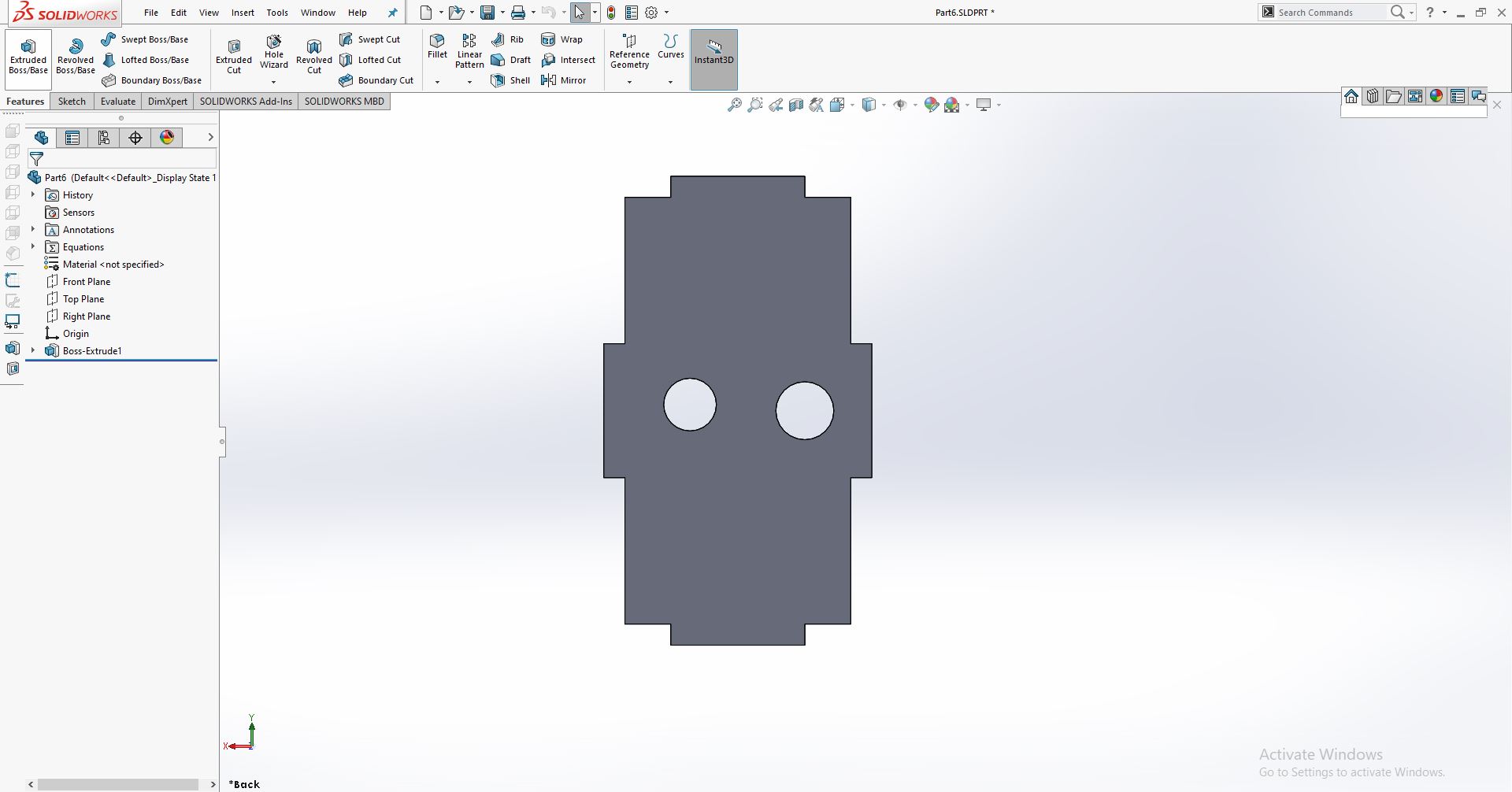
Now I Design the Top part for the sketch As:
Desiging the top part.
For the support and slot for the sensor and nozzle I design as:
supporting part for nozzle and sensor.
Remaining parts and assembling
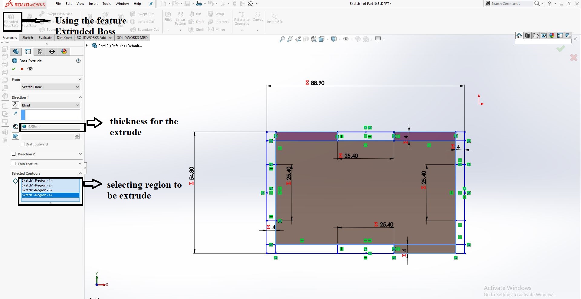
After that I use many tools of solid work to design my final project sketch . I used the tools as: Equation export it and also import it in other parts. I also use the sketch and select the rectangular and give parameters (dimension) through the equations. I also used the features as extrude base and also the mirror entities at last I assemble them together as:
After Drawing the design in solid work the final image of design is as :
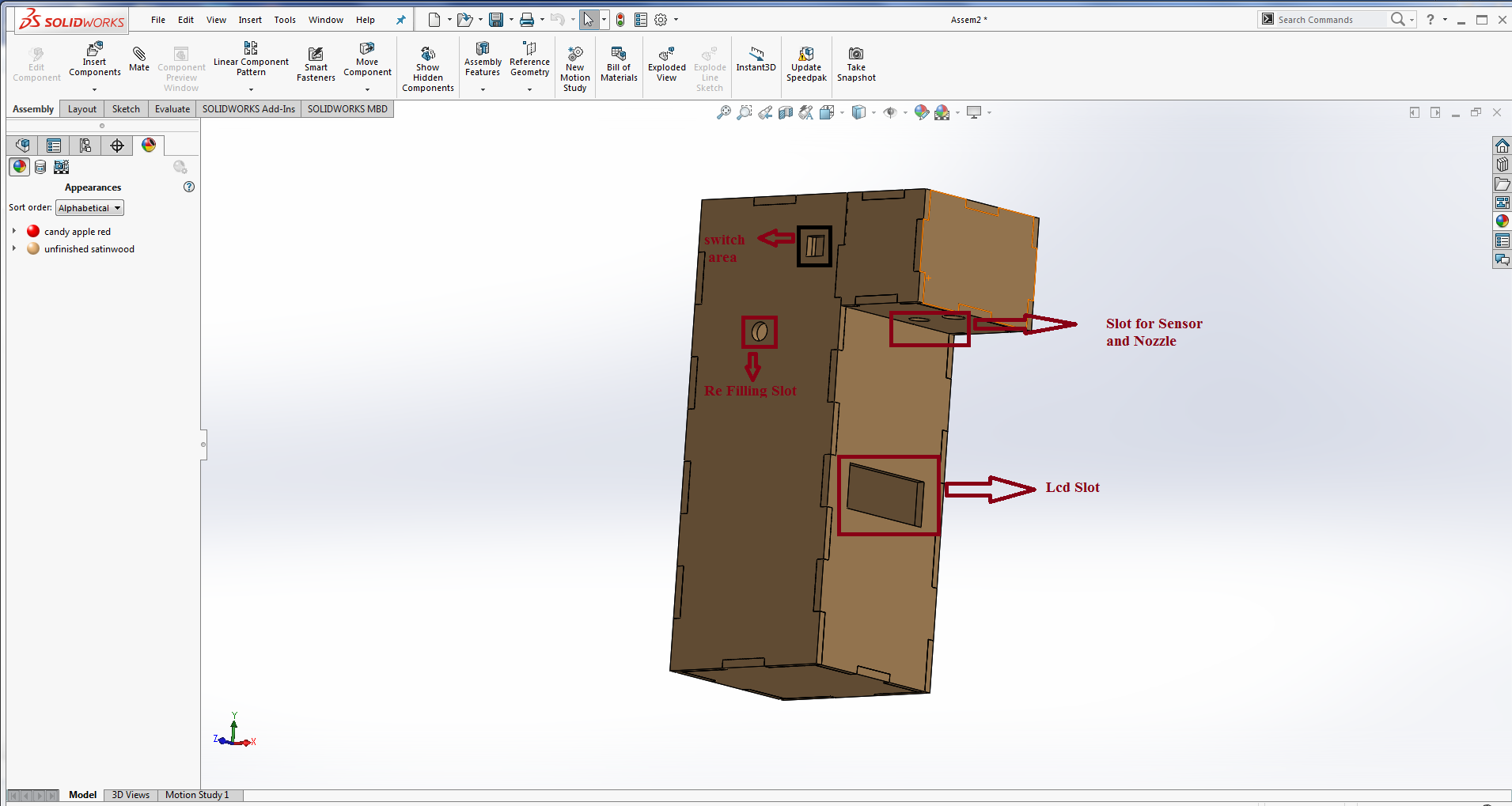
Download all files from here