9. Embedded programming
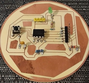
The assignment of this week requires we program a board to do something meaningful. We could design a new circuit, mill the board, and sold the components, like we have done in 7. Electronics design, or we could use the hello world board created in the assignment Electronics design and program it to give a different meaning for it. I have decided to use the hello world board and program a morse code convertor using the LED. The push button will be used to start blink the output string message in the LED.
Morse code
Morse code is the alphabet used by the electrical telegraph that is a point-to-point text messaging system, used in the end of 19th and beginning of 20th century. The telegraph uses coded pulses of eletric current (sounds) to transmit the information over long distances. Samuel Morse was the inventor of the telegraph and the morse code was named after him.
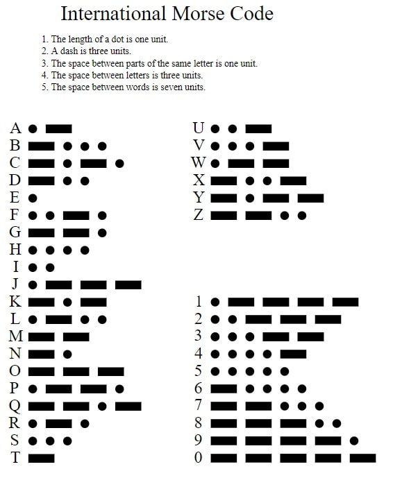
Morse code is represented by a sequence of dots and dashes that combined represents each letter in the alphabet. The duration of a dot is the basic unit of time measurement in the transmission of the code. The duration of a dash is three times the duration of a dot. The space between each dot or dash is the absense of signal, called space, equal to a dot. The letters of a word are separated by a duration of a dash. The words are separated by a space equal to seven dots.
The efficiency of the code is that the lenght of the symbols is approximatelly inverse to the frequency of occurrence. This means that most used symbols will have short lenght to speed the communication. Bellow you can see the alphabet in international morse code.
PCB connection
To upload the code in the board, it was used Arduino as interface between the computer and the hello world board version 2. The configuration needed to Arduino works is explained at 5. Electronics production, section Programming board > Setup Arduino. The connection used between the board and the arduino, is also explained in the previous link.
Important to use the correct order of the jumper ISP-6 from your board in the arduino, otherwise the code will not be uploaded. Bellow there is the order of the jumper ISP-6 from top to bottom according to the image bellow.
The pins to be used from the Attiny45 can be found in the datasheet of the microcontroler (here). In the image bellow (from the datasheet) you can see which pins from ATtiny45 that is needed to make the J1-ISP connection with Arduino. ISP connection needs the following pins: RST, MOSI, MISO, and SCK.
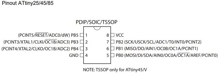
The table bellow summarize the J1-ISP connection that need to be done between the ATtiny and Arduino. Remember that the ISP code should be loaded in the Arduino before programming the board. Once connected, Arduino can work as bridge to upload the code into the microcontroller ATtiny45.
| J1 - ISP | Attiny | Arduino |
|---|---|---|
| GND | GND | GND |
| RST | PB5 | D10 |
| MOSI | PB0 | D11 |
| MISO | PB1 | D12 |
| SCK | PB2 | D13 |
| V | VCC | V |
The LED is connected in the PB3 connection from the ATtiny45 and the button is connected in the PB4. To program the board we need to use these constants in the code and change/read their values.
The program to be loaded requires to implement two methods: setup and loop. The former one is executed uniquely once when the board is connected to electricity. The second one is executed constantly while the board has electricity. You might use the function delay to be able to notice changes in the LED or button, otherwise some changes will not be noticed because of the speed of processing time.
Source code
In our board, the electrical pulse (sound) of the morse code will be replaced by a blink of the LED. I will use the a blink of 200ms that will represent one dot. This implementation will simply show the word SOS in morse code. The push button will trigger the start of the morse code.
The source code is divided in the main parts: (i) variables declaration; (ii) local declared functions; and (iii) main functions.
Variables
The first variables to be declared are the ATtiny pins used to have one input and output in the board, respectivelly push button and LED. Then it was declared a variable to represent the morse code alphabet and the string that will be shown as output. The dot_duration is the basic unit of time in the morse code and will be used to blink a dash, and the space between dot/dash, letter and words. The remaining variables are used to control the program.
int BUTTON = PB4;
int LED = PB3;

//letters A-Z in Morse code
char *letters[] = {
  ".-", "-...", "-.-.", "-..", ".", "..-.", "--.", "....", "..",
  ".---", "-.-", ".-..", "--", "-.", "---", ".--.", "--.-", ".-.",
  "...", "-", "..-", "...-", ".--", "-..-", "-.--", "--.."
  };
char *string = "SOS";

int dot_duration = 200;
char ch_dot = '.';
char ch_dash = '-';
boolean start = false;
int curr = 0;
Declared functions
Two functions were defined to support the morse code implementation: blink_dot_dash and blink_letter. The former one blink the LED one small unit of the morse code (code, that is a dot or a slash) of the refered letter. It will turn the LED on and off with a delay of the unit being blinked. In the end will have a delay between the next unit of the letter. The second one blink the units of the morse code for the reffered letter (calling the first function). It will use the variable letters (which contains the morse code alphabet) to know the sequence of morse code unit to blink. In this implementation, the characters of the string must all be uppercase, otherwise the function will not work. It can be easily adapted to strings lowercase, for instance creating one function to get the morse code unit for a character independent of the upper or lower case.
void blink_dot_dash(char code){
  digitalWrite(LED,HIGH); //turn on LED
  if(code == ch_dot)
    delay(dot_duration);
  else
    delay(dot_duration*3);
  digitalWrite(LED,LOW); //turn off LED
  delay(dot_duration); //space between dot/dash
}

void blink_letter(char ch){
  char *code_letter = letters[ch - 'A'];
  unsigned int i = 0;
  while(code_letter[i] != NULL){
    blink_dot_dash(code_letter[i]);
    i++;
  }
  delay(dot_duration * 3);//space between letters
}
Main functions
As explained previously in 7. Electronics design, attiny has two main functions: setup and loop. The function setup will just initialize the button in the board as input, and the LED as output (like it was done before). The variables could be initialized here as well, but I choose to initialize in their declaration. The function loop will use the declared functions to blink the LED according to the string that will be send via morse code. I have chosen the string SOS that should have the following pattern in the morse code: S=…, O=---, and S=… When the button is pressed, the flag start is set to true, and it will start to send the morse code. When start is true, the string SOS will be looped blinking each of its character using the function blink_letter. A delay of 7 times the duration of a dot is used to guarantee the space between two words in morse code. The flag start is set to false again, and the LED will be turned off. The board expect another push in the button to send the morse code.
void setup() {
  pinMode(BUTTON, INPUT_PULLUP); //init button as input
  pinMode(LED, OUTPUT); //init LED as output
}

void loop() {
  // when button pushed, invert start.
  if (!digitalRead(BUTTON)){
    start = !start;
  }

  if(start){
    for(curr = 0; string[curr] != NULL; ++curr){
      blink_letter(string[curr]);
    }
    delay(dot_duration*7);//space between words
    start = false;
  }
}
Download the INO file of the microcontroler code for the morse code - SOS.
Group Assignment
Ingegno - Embedded programming