Week 10
Another electronics week and another opportunity for me to gain more experience on how electronics work. This week is about input devices which it technically all kind of sensors that can be used for my final project,This week' assignment:
1. Group assignment:
probe an input device's analog levels and digital signals.
2.Individual assignment:
measure something: add a sensor to a microcontroller board
that you have designed and read it.
Learning outcomes
- Demonstrate workflows used in sensing something with input device(s) and MCU board.
Group Assignment:
Oscilloscope:
The oscilloscope is an instrument commonly used analyze the signal waveform of input devices , The device plots the instantaneous signal voltage as a function of time on a graph so it is really useful for debugging because it visualized the signal that is coming from the input device.The horizontal sweep of any oscilloscope is measured in seconds per division (s/div),and The vertical deflection is measured in Volt per division(V/div).
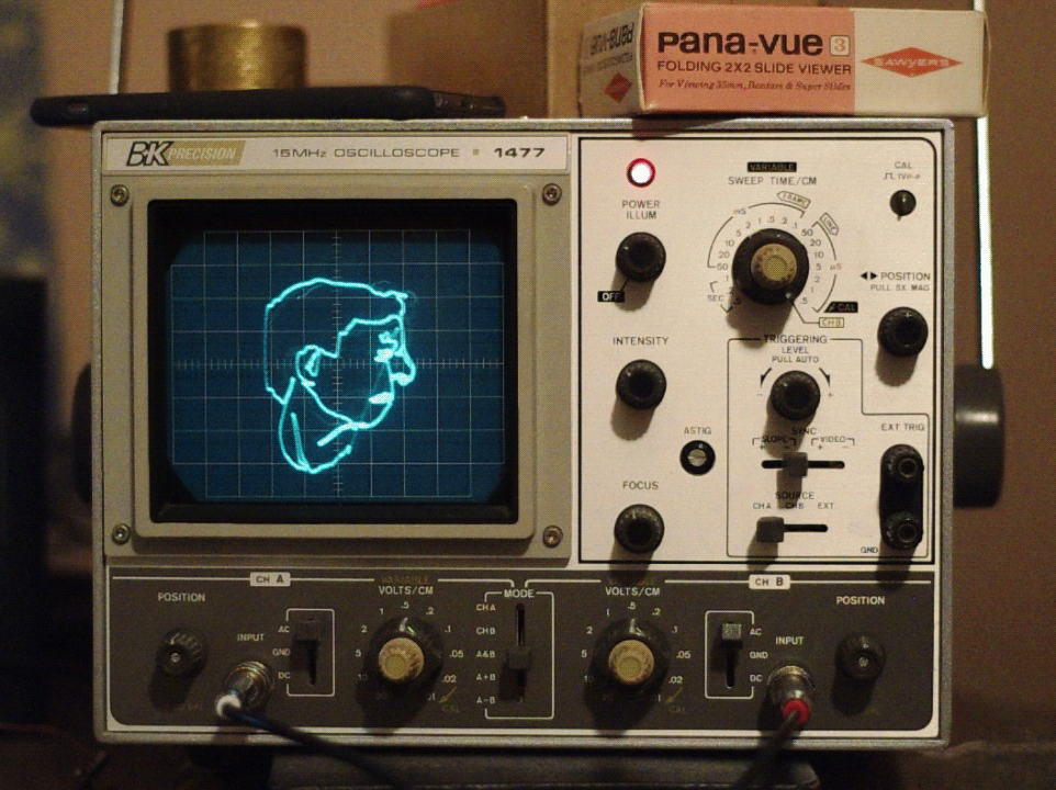
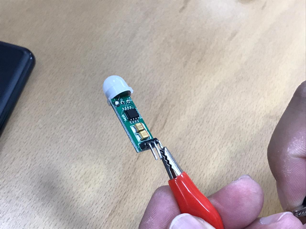
PIR motion sensor:
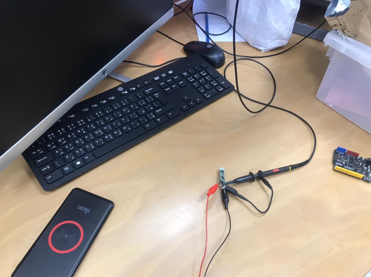
For the group assignment we decided to measure the PIR motion sensor signal using the oscilloscope to visualize the signal and to have a better understanding how this sensor works:
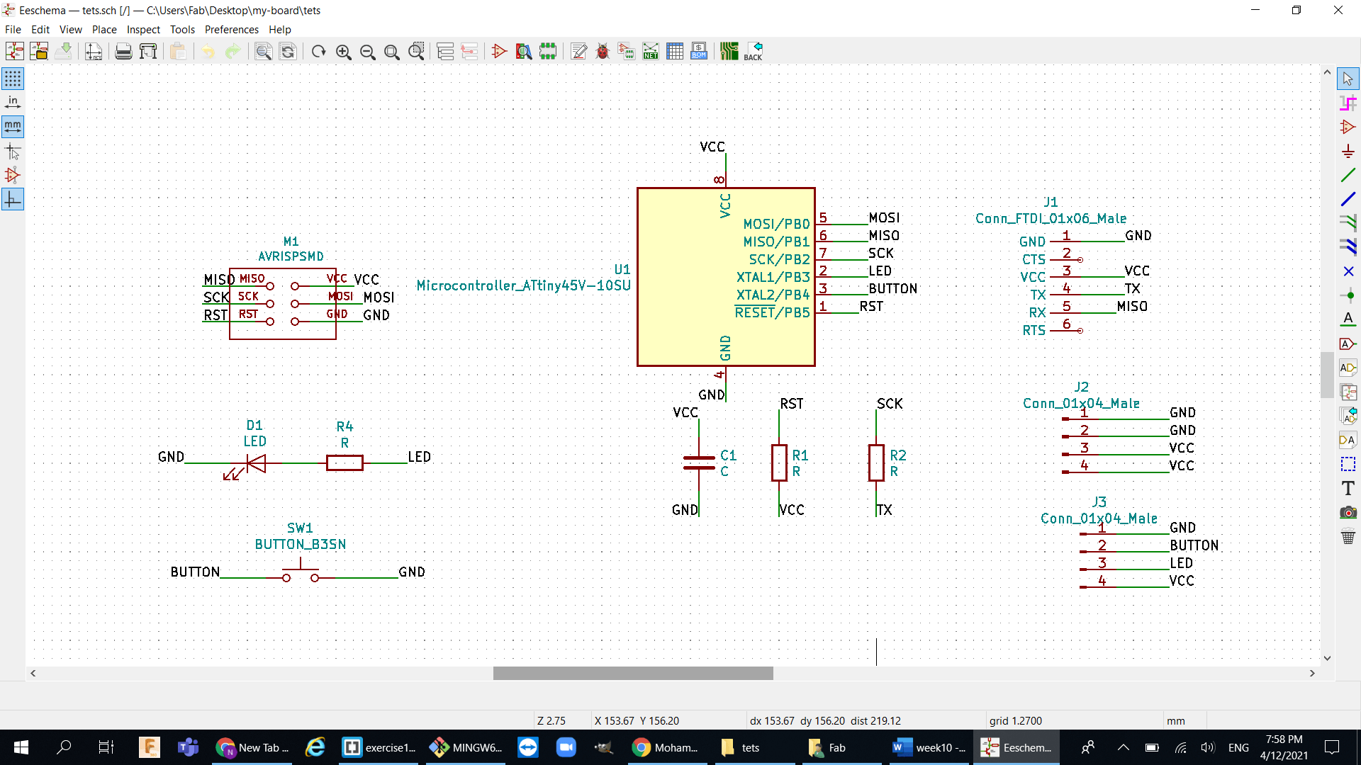
Kicad Design:
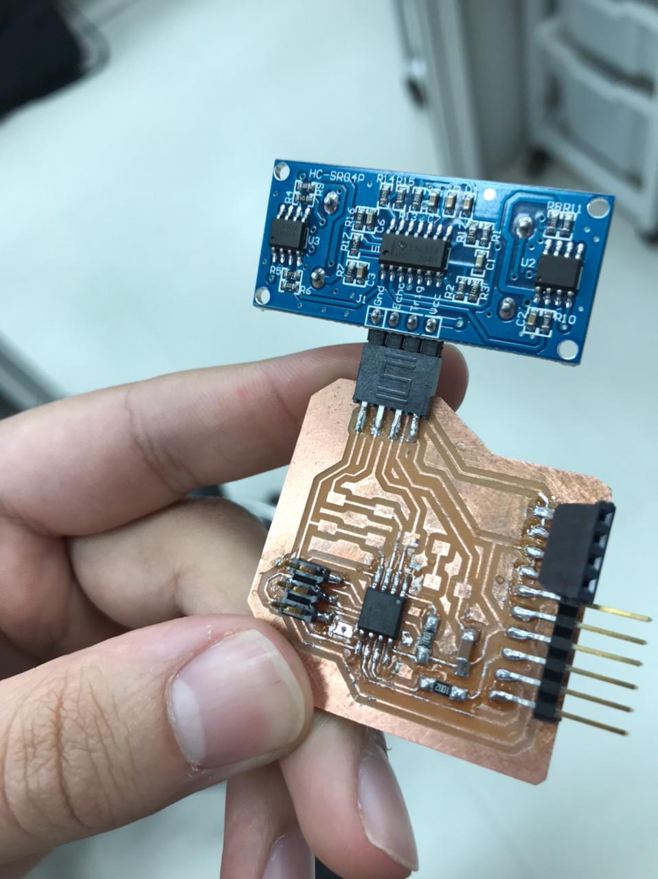
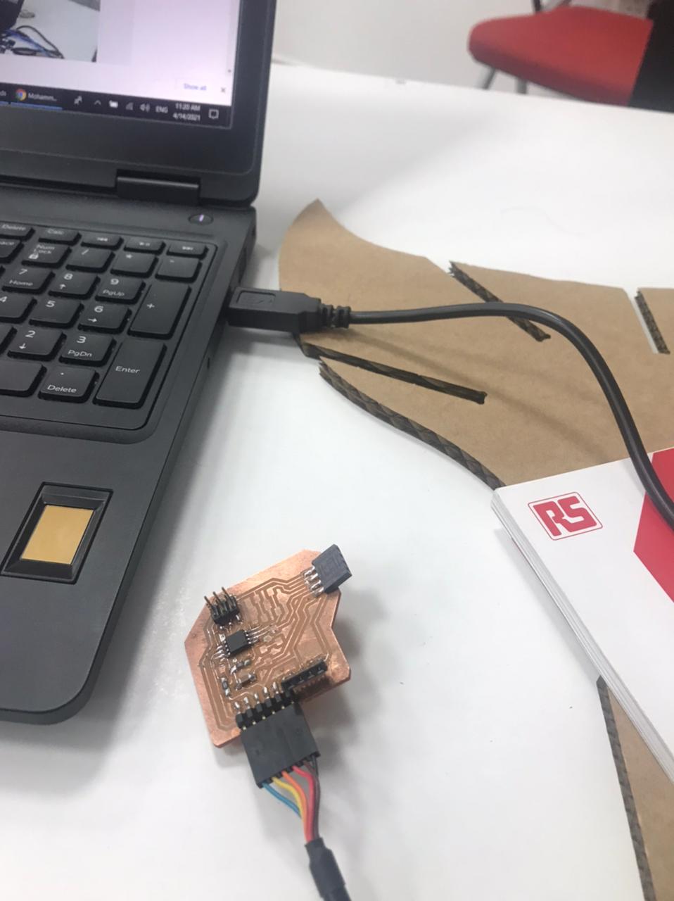
- Honestly I didnt want to spend a lot of time here because I want to start working on my final project and so what I did is I took my design in week 6 then added some connector to it and rewired in the software so I can connect the ultrasonic sensor to my board, here is the schematic of the redesigned board :
-
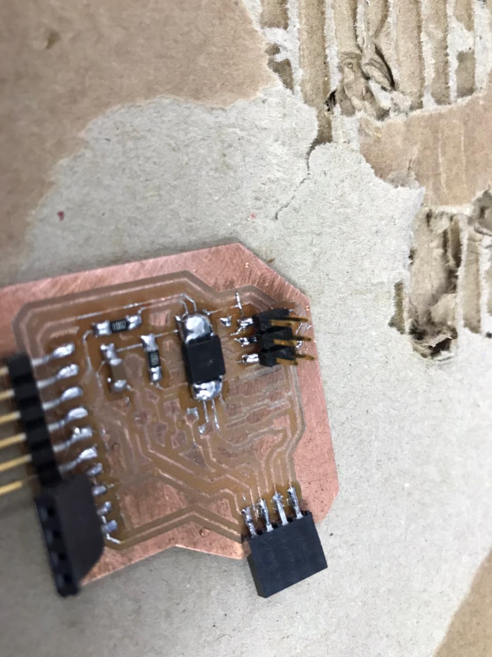
Here is what my board looks like after re-wiring it:
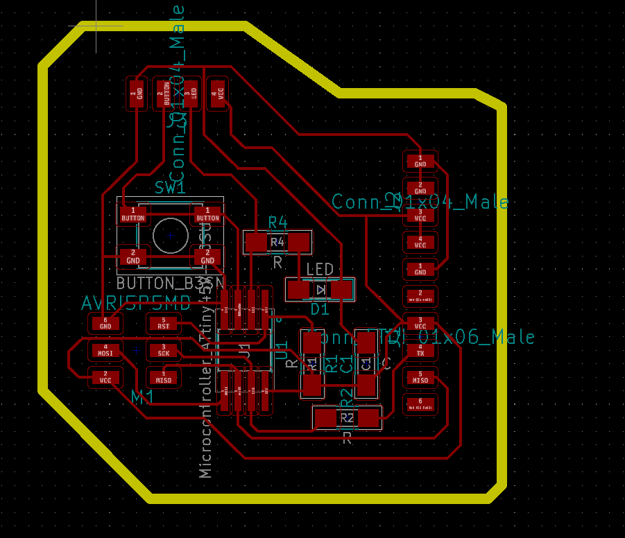
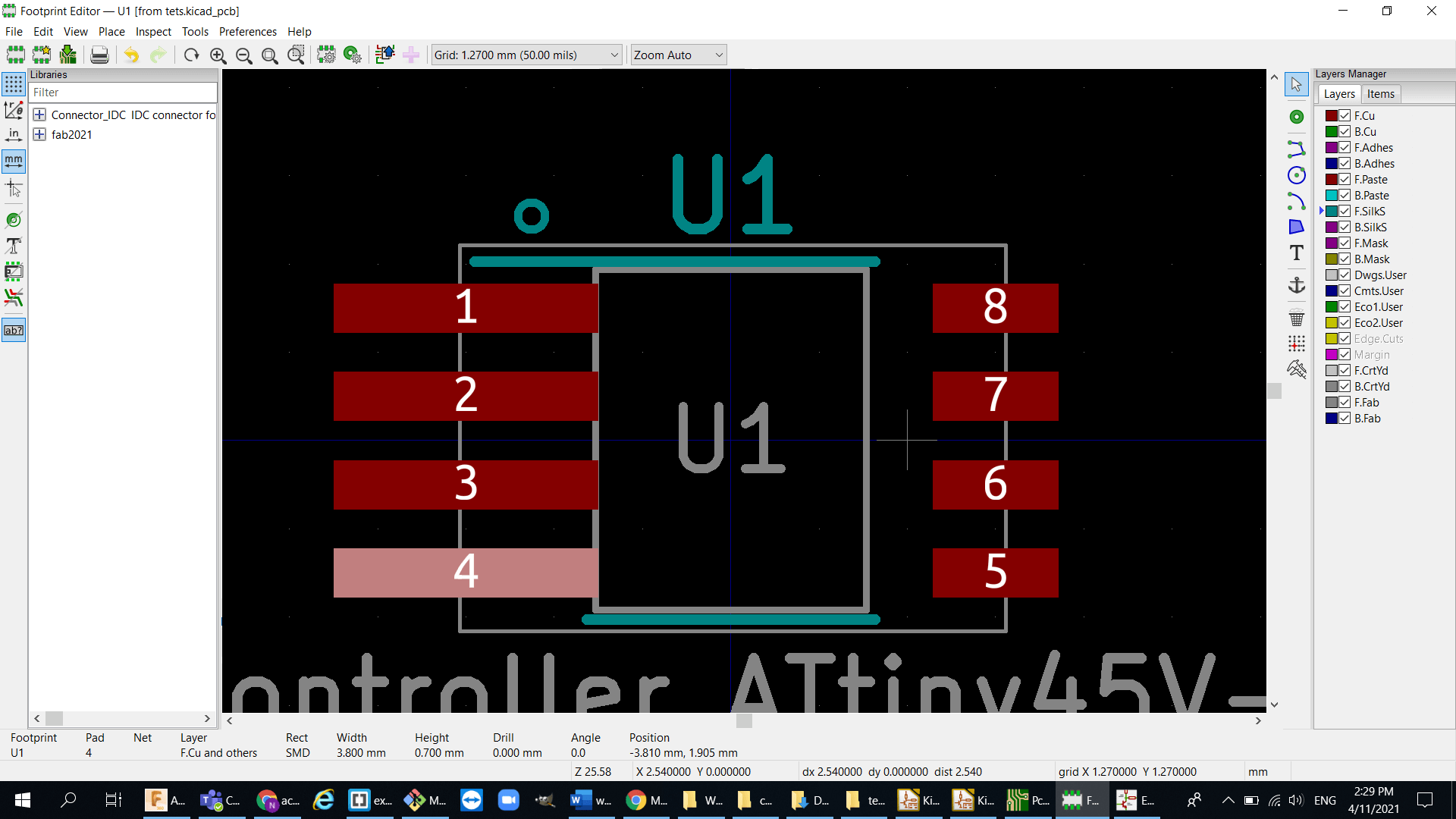
- Last time I designed a PCB it was pretty hard for me to solder the Atiny45 Microcontroller because the pads were pretty small and barely fit so what I did is I edited the pads size in KiCad and made then a bit bigger so it is easier to get soldered.
-
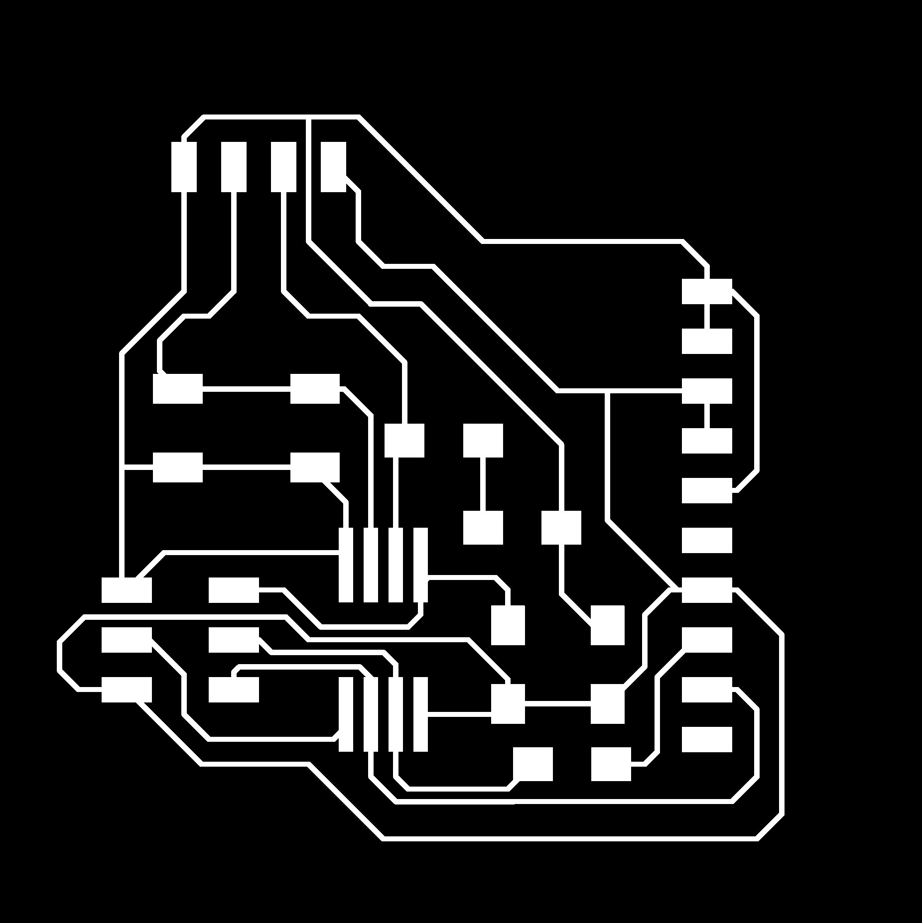
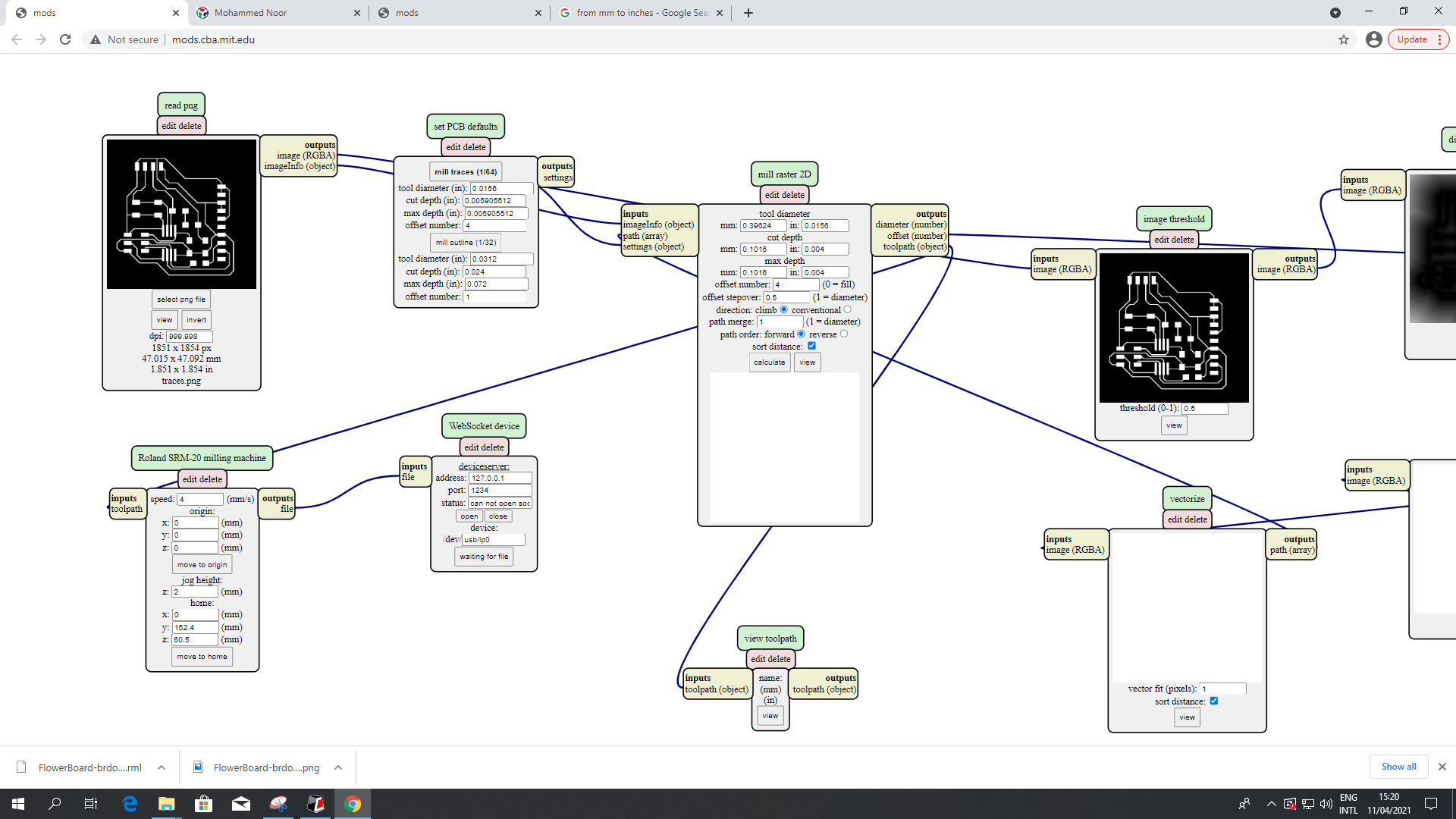
And Again I used Gimp to extract the traces and edges for the milling machine:

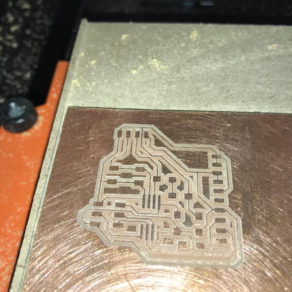
- Milling and stuffing the board:
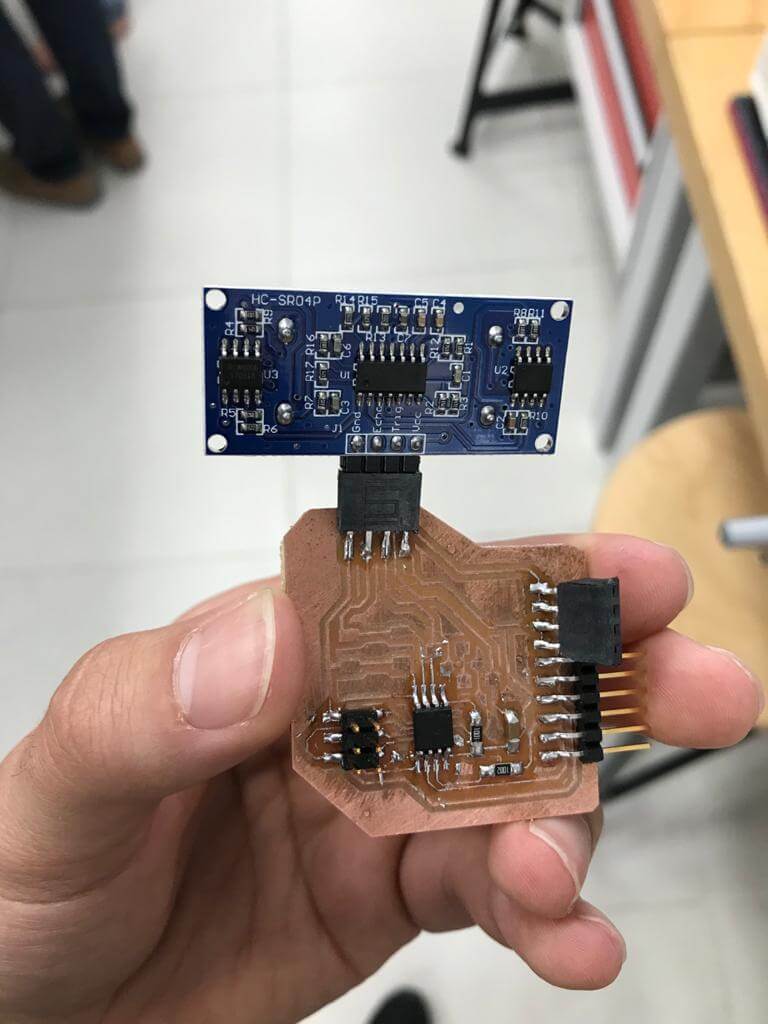
UltraSonic Sensor:
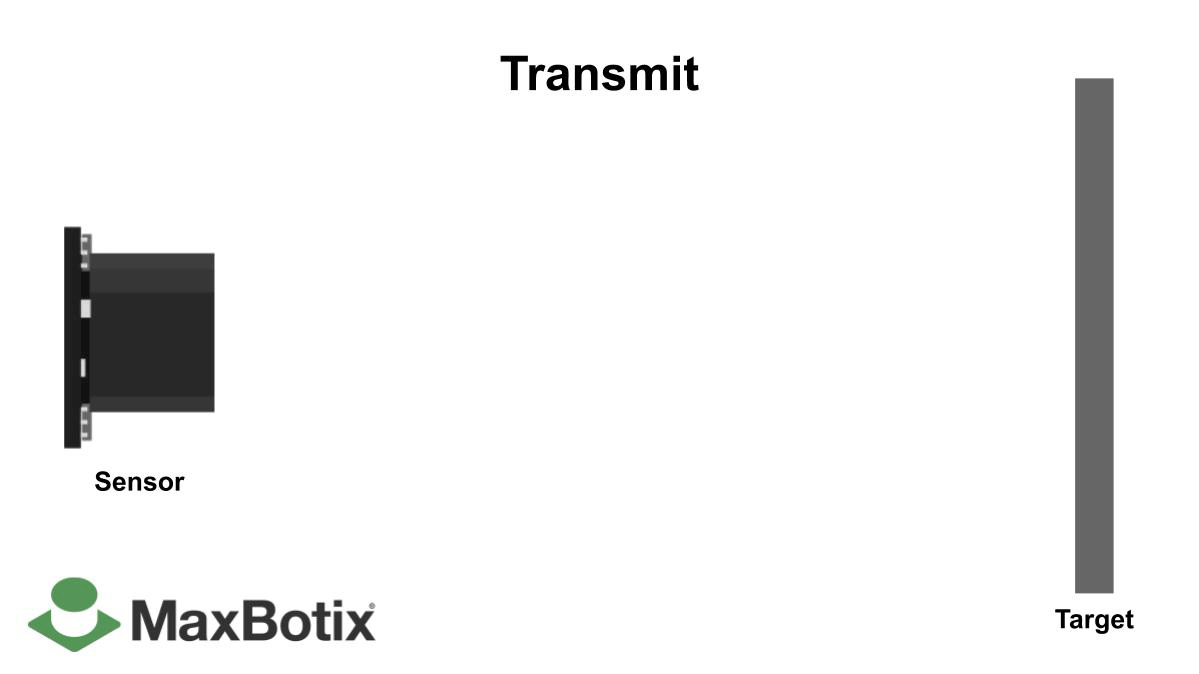
An ultrasonic sensor is a device that uses ultrasonic sound waves to determine the distance to an object. it sends and receives ultrasonic pulses that transmit information about an object's proximity using a transducer. it is one of the most reliable ways to sense proximity and track speeds.

The way this device work is kind of simple, it sends waves that goes through the air and bounces back to the sensor as it encounters an obstacle or target. The distance can be determined by multiplying the travel time by the sound speed. To know more about this device check out this link.
Programming it:
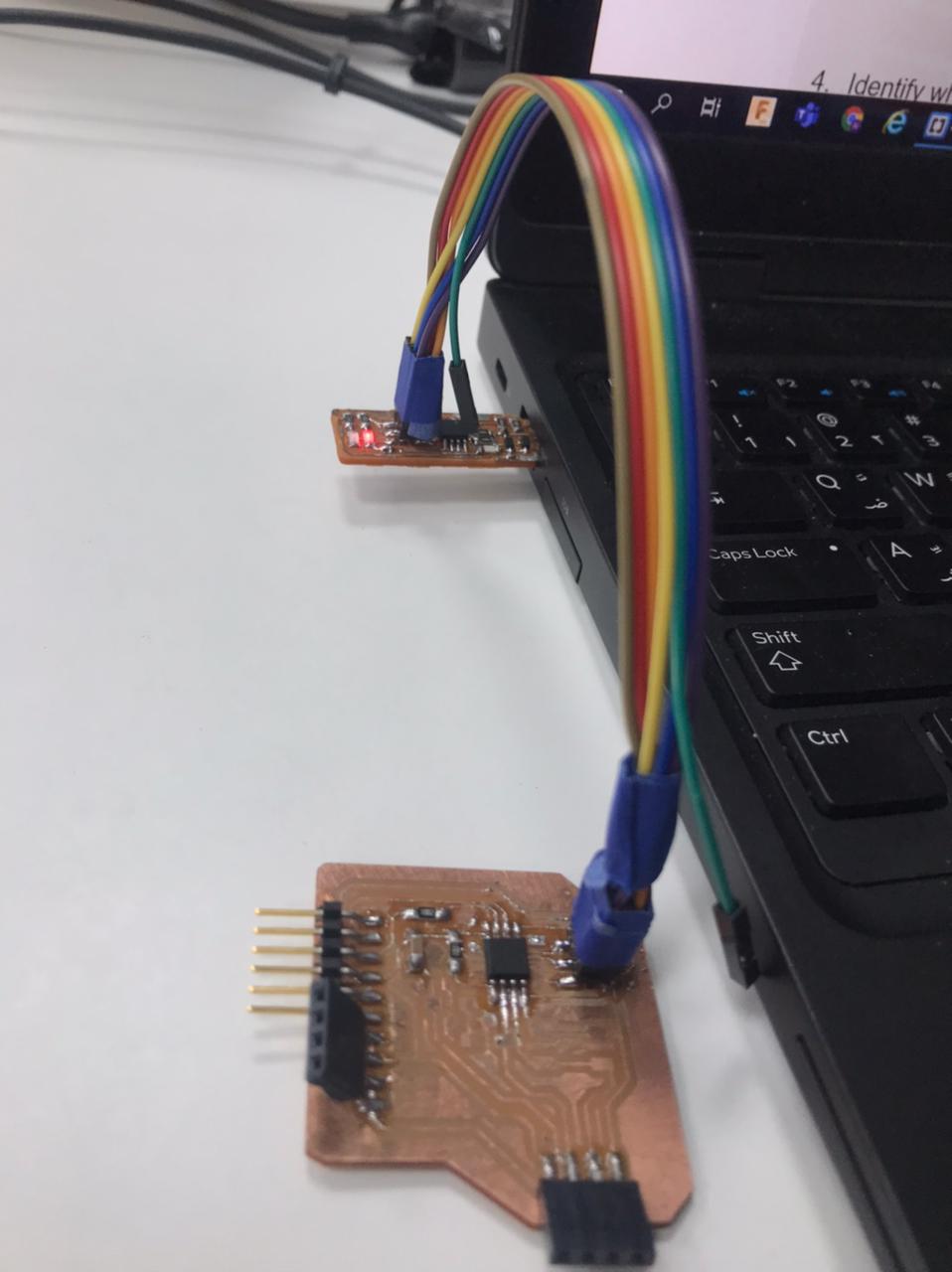
I will be using my FABISP programmer that I made in week4 to program the sesnsor then I will connect it to an USB to FTDI cable to communicate with it.it took me alot of time to understand how to do it but I finally did and here are the steps :
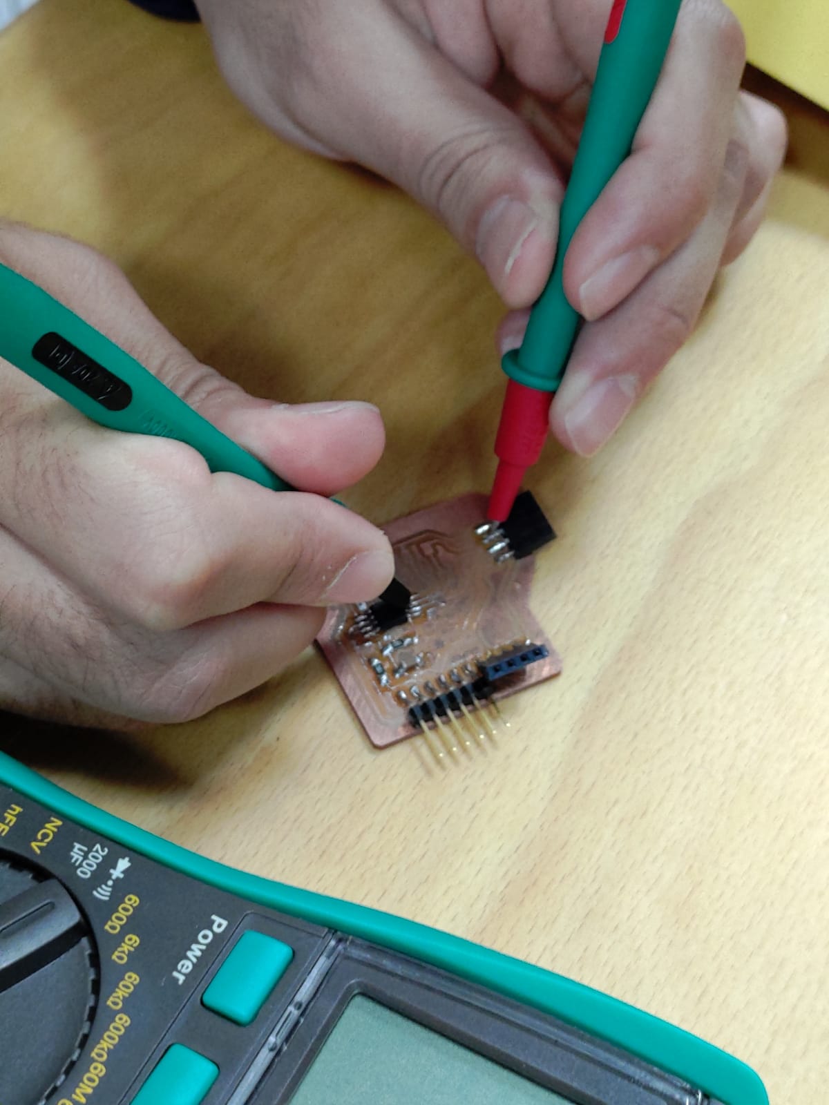
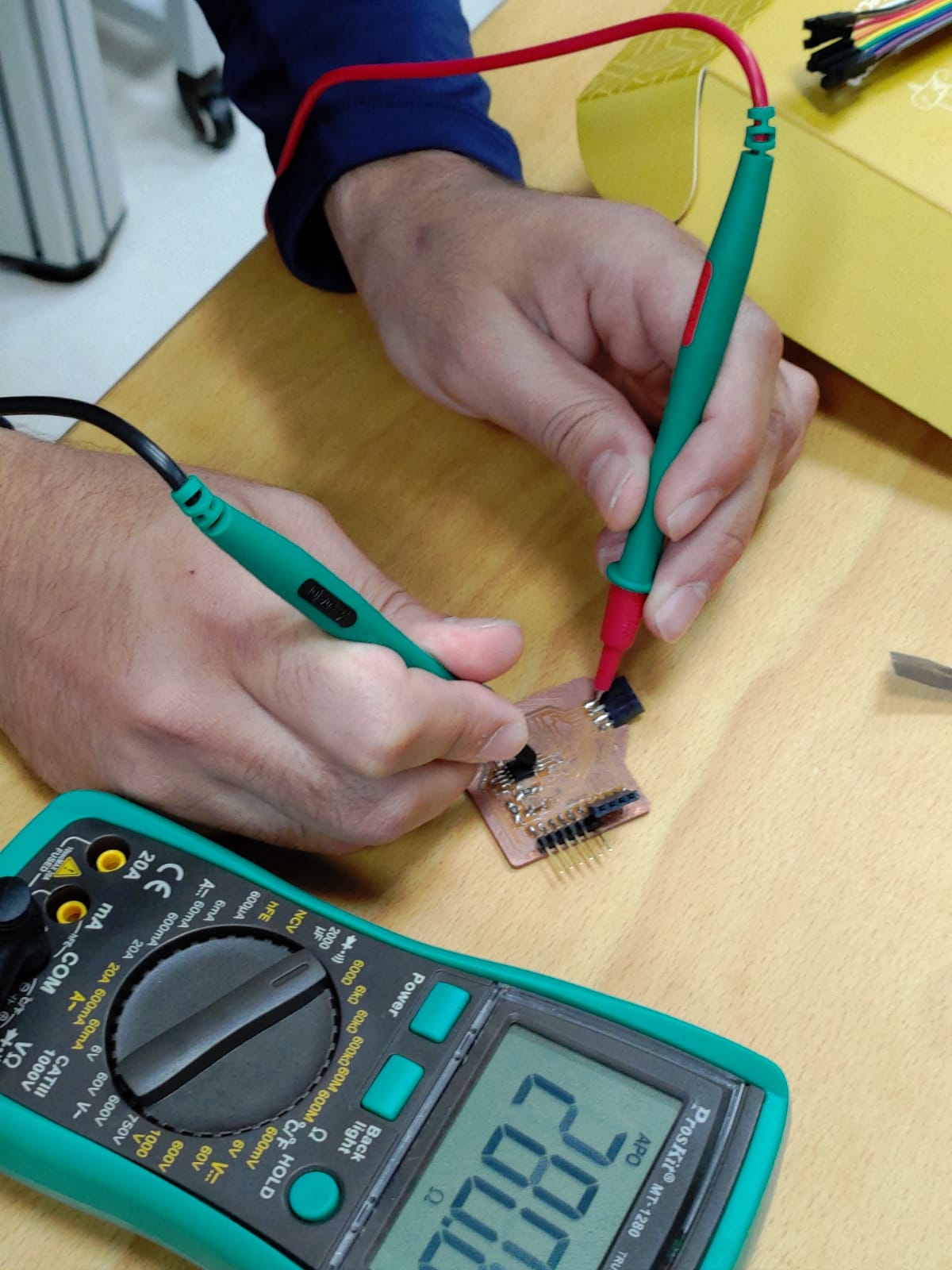
- Check that everything in your board is working as intended and that there is no circuit shortage and most importantly check that your microcontroller is in the right direction because mine was in the wrong direction and I ended up blowing the sensor (use the multimeter).
- Connect your board to the programmer
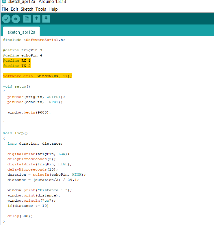
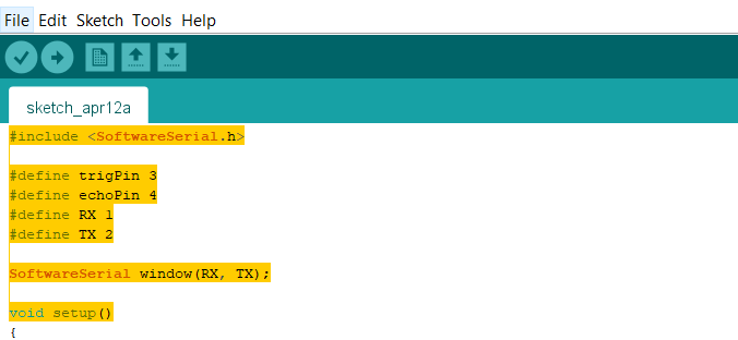
- Now because my USP Tiny programmer did not have the tx and rx library I had to write a code that can define this library:
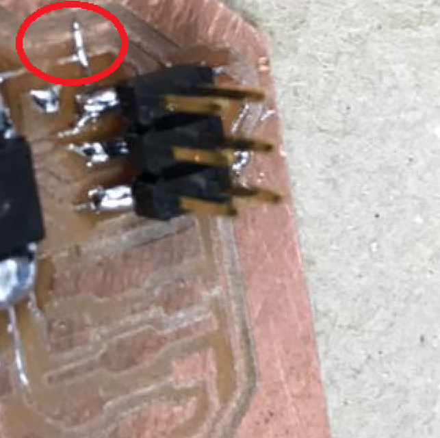
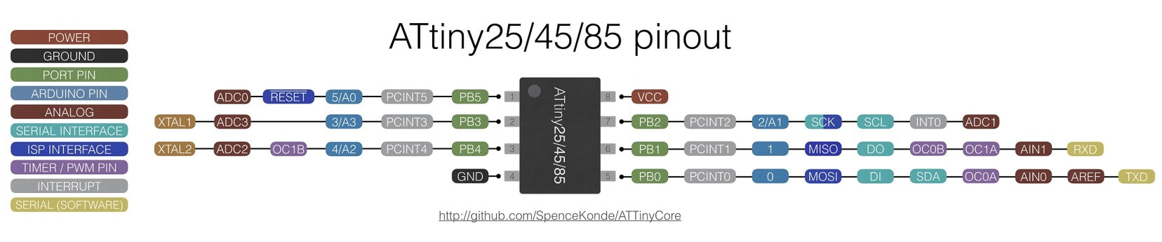
- Identify what pin is your sensor connected to and this is a very helpful image that can help you understand what pin number to use.
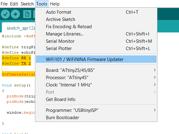
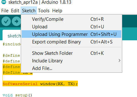
- Now the code is ready, make sure everything is connected properly then hit
upload using programmer
.
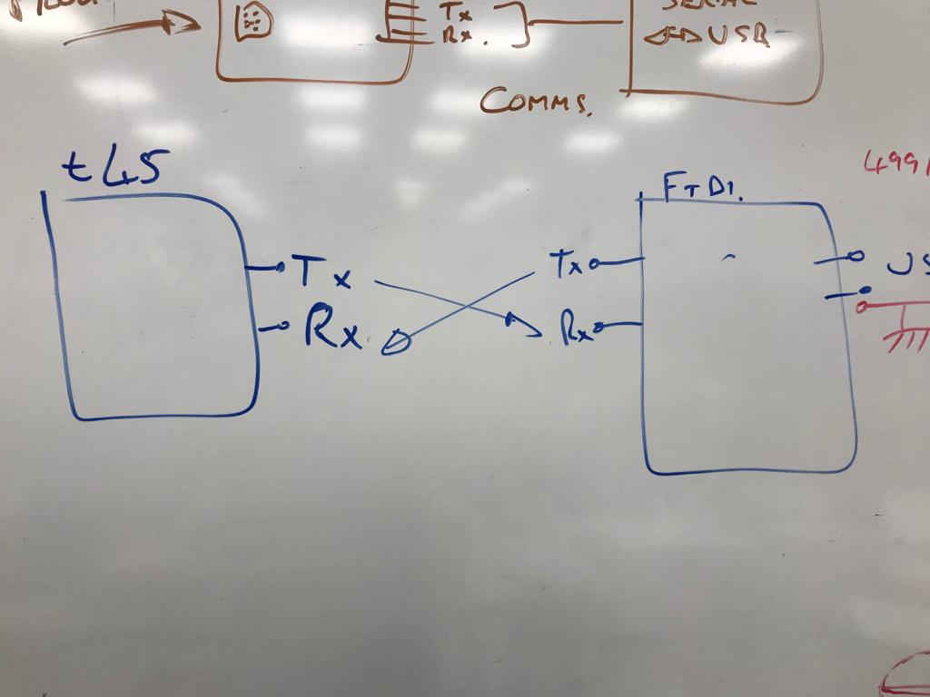
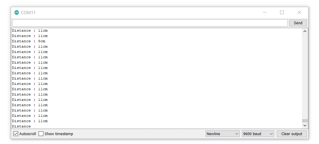
- After we programmed the board it is time to communicate with it so I will be using a
TTL-232r-5vcable and I had to install the driver for it so I can have the port to see the serial monitor. - Finally testing the sensor:
code explanation:
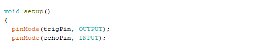
- First the setup the trig pin should set as output because it will trigger the ultrasonic pulses and the echo pin should be set as input because it will because produce pulses when the signal is received.
- then in the loop function first thing that must done is clearing the trig pin that's why we set it to low for 2 µs. then we set it to high for 10 µs to start producing ultrasonic waves
- after that we use the pulse function to read the travel time and we give this function a variable which is duration so in this function we the echo pin to HIGH because The pulsIn function will start timing after waiting for the pin to go HIGH, then it will stop timing after waiting for the pin to go LOW until the sound wave ends.
- Then we use this equation to calculate the distance
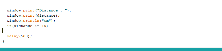
- Finally we print the results on the serial monitor
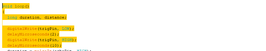
duration = pulseIn(echoPin, HIGH);
distance = (duration/2) / 29.1;
Problems I faced this week:
- I kind of rushed my self in the design so I ended up flipping the ground and vcc pins for the sensor which explains why the sensor is the other way around but it is no big deal.
- I soldered the Microcontroller in the wrong direction which almost blew it and some of the magic smoke came out lol but luckily it did not break.So I had to re-solder it to put it in the right direction.
- Some solder was connecting multiple traces together which caused shortage in the circuit.
- The last challenge I faced was communicating with my board through the FTDI cable and after many tries my instructor carl suggested that I flip the rx and tx pins so the tx is a one device connects to rx to other device and so the problem is that the label on the board for the ftdi connector is not tx it should be rx because the pins is with respect to the cable noy with respect to the board and that is why I flipped them.