On the Applications and Implications week (May 23rd-27th), I spent the week cutting out rough measurements of glasses with cardboard (and acrylic once I had my measurements down), using and finding references for my glasses eventual appearance, and making/designing the first draft of the pcb I'd want to use. When laser cutting the glasses I went through three different designs (with measurements based off of safety goggles from the lab) before eventually just using the glasses I had at home for reference and sketching over my own face for measurements (ironically I ended up finding the lost fusion prototype design I made weeks prior that ended up being the exact measurements of my glasses) but nevertheless I stuck with the design that I conceived since the board I made needed more space than what the prototype was giving.
╰─━━━━━━━━━━━━━━━━━━━━━━━━━━━━━━─╯
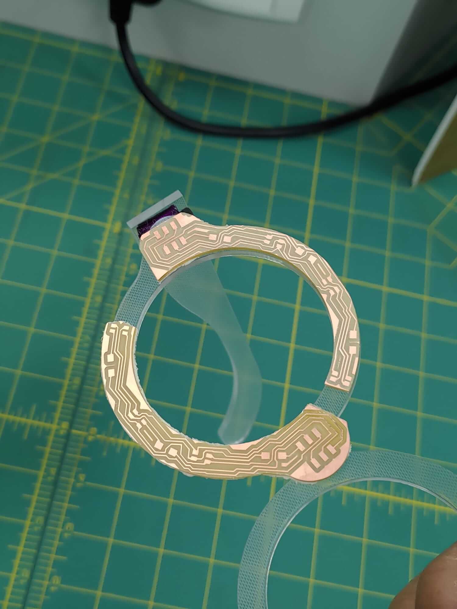
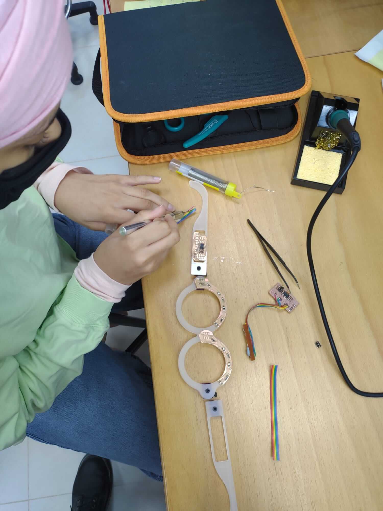
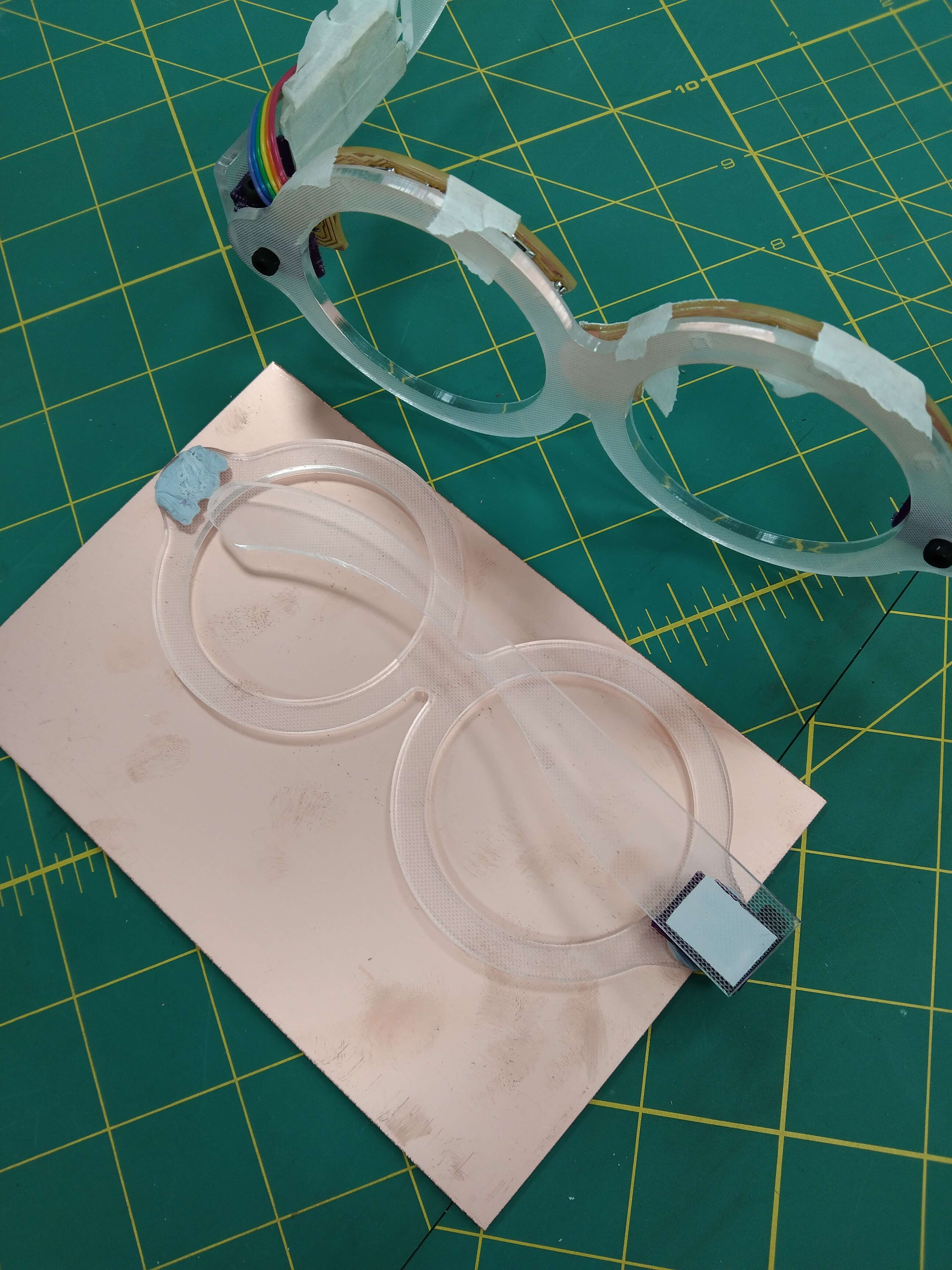
Working on my PCB design and dipping silicone
╭─━━━━━━━━━━━━━━━━━━━━━━━━━━━━━━─╮
─━━━━━━━━━━━━━━━━━━━━━━━━━━━━━━─
On Sunday (May 30th) I worked on finishing my pcb design and cutting out my newly designed pcb for my glasses. During my first cut the milling part was a success but one it started getting cut out it cut over some traces (due to a mistake while using gimp). In order to fix this problem I had to do a bit of rearranging by moving the tracks and I managed to make a fixed board (though it was a bit wider than the first). After milling the board I had it taped to the glasses to check the measurements and found out that the board was a bit bigger than the frames (only by a few mm) I soldered it anyway and programmed it to do different color sequences and I also tried putting dyed silicone on my glasses (but it didn’t turn out well) the process was a bit frustrating since the silicone is messy and complicated to work with when a mold isn’t present.
╰─━━━━━━━━━━━━━━━━━━━━━━━━━━━━━━─╯
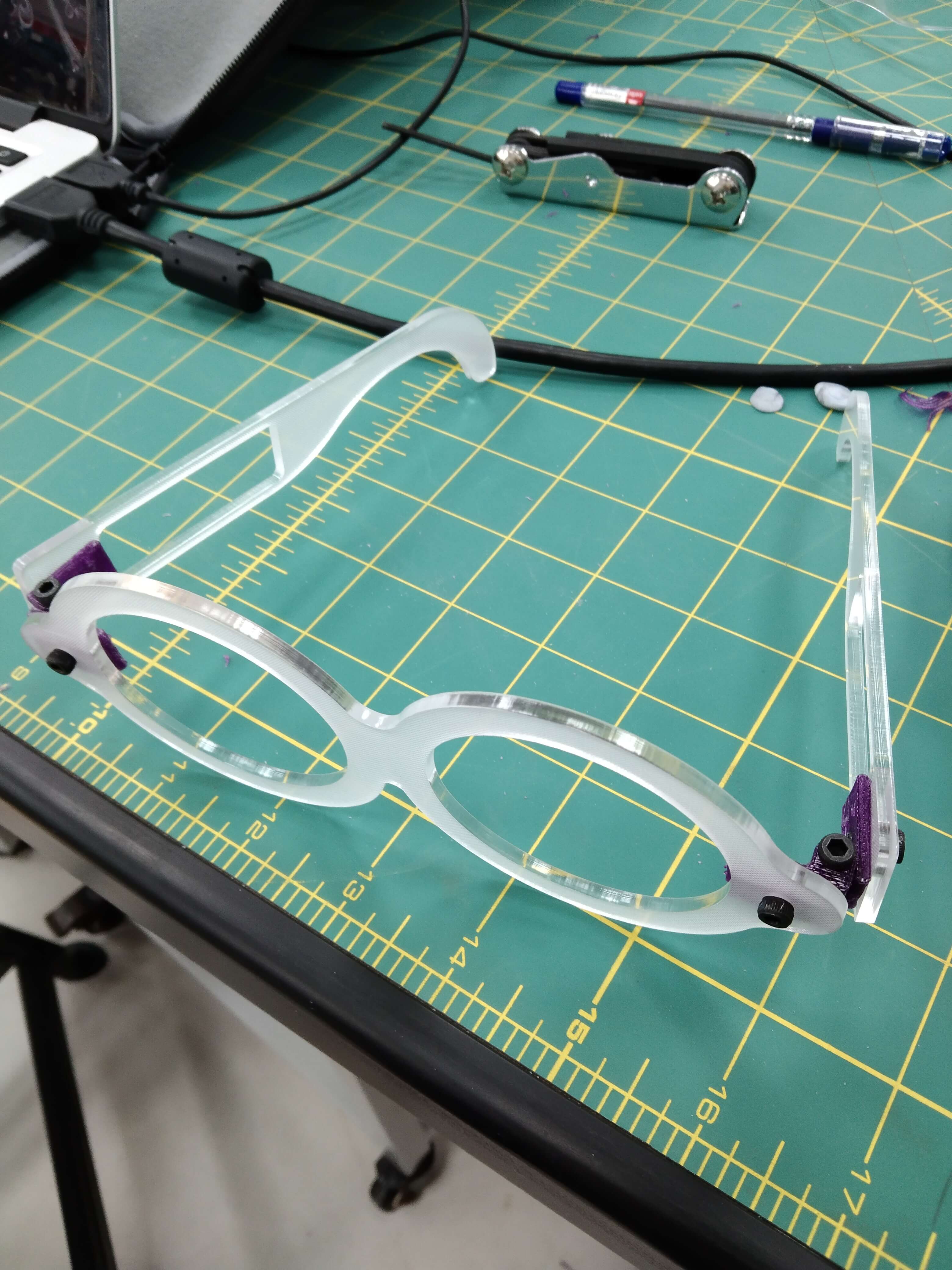
Working on new laser frames + 3D printed hinges
(and using a new system/swapping to Macbook)
╭─━━━━━━━━━━━━━━━━━━━━━━━━━━━━━━─╮
─━━━━━━━━━━━━━━━━━━━━━━━━━━━━━━─
On Monday (May 31st), I worked on the L.E.Glasses. First I saw the finished result of the silicone covers from Sunday and wasn’t satisfied so I took them off. Then I set up my macbook to be my main operating system so I no longer use the provided computer. For most of the day I spent my time setting up my macbook with brackets, arduino, kicad, and git (using terminal)I also tried designing some molds for the arm encasings and nose bridge but I ended up just working on the glasses and made drill holes on the glasses, hinges, and arms and a battery area on the arms for bolts and batteries. After doing some redesigning I set up the glasses to be cut (I printed both arms on the same side by mistake) and made the improved hinges.
╰─━━━━━━━━━━━━━━━━━━━━━━━━━━━━━━─╯
Making new 3D printed hinges and cutting bolts
╭─━━━━━━━━━━━━━━━━━━━━━━━━━━━━━━─╮
─━━━━━━━━━━━━━━━━━━━━━━━━━━━━━━─
On Tuesday (June 1st), I worked on fitting the newly cut frames with the improved hinges. I started by first drilling through the hinges (drilling through the front holes too which was unnecessary) and once I was finished I started screwing them into the frames. The bolts were a bit long so I learned how to use an angle cutter with a cutting disk and a grinding disk. After cutting multiple bolts and screwing them I came across numerous problems like one of my bolts were chipped in the thread (which cut away at the hinges plastic), one was short (which wouldn’t go through fully), and when screwing in the bolts I would create cross-threading from being too forceful and not putting the bolts in straight (this would cause some hinges to be loose on the arms of the glasses). With the help of Mr. Carl the glasses stopped having issues with being loose since he made more hinges and used a thread cutting tool for the hinges since it’s more reliable than forcing the bolt through. Once the glasses were more sustainable I tried them on and was satisfied with the result.
╰─━━━━━━━━━━━━━━━━━━━━━━━━━━━━━━─╯
Soldering, measuring, and new ideas
╭─━━━━━━━━━━━━━━━━━━━━━━━━━━━━━━─╮
─━━━━━━━━━━━━━━━━━━━━━━━─
─━━━━━━━━━━━━━━━━━━━━━━━━━━━━━━─
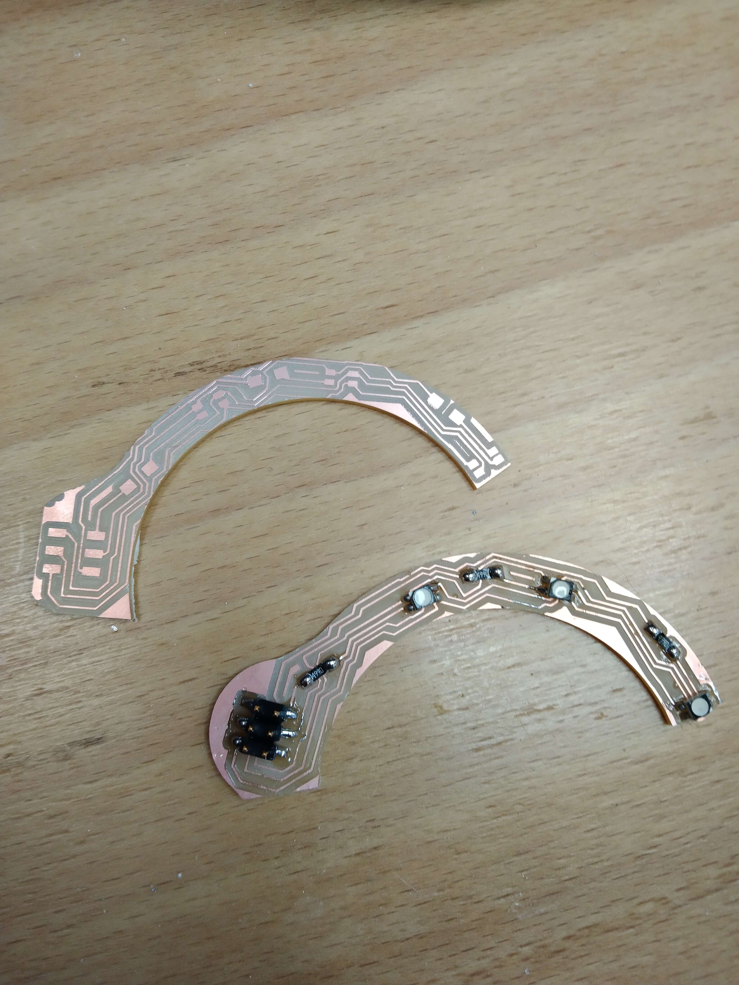
On Wednesday and Thursday (June 2nd-3rd), I spent more time documenting and working on the pcb, cutting out another for the other side of the glasses. After soldering the newly cut duplicate and placing the pcbs on the frames I noticed how there would be a huge spacing problem with the boards since they’re separated, and since the battery will only be on one side it would be complicated to reach towards the other board using wire. We thought up a few ideas like wrapping wire around the top rims of the glasses so they would reach the battery and board easily but it seemed like a bit too much work to go through. We eventually decided that we would make a double-sided full-length board for the top half of the glasses instead of making them separately. When designing the board in kicad I was a bit confused since the board had a front and backside (I also had to use vias in order to connect the tracks from the front to the back) but it ended up not being as complicated as I initially thought.
╰─━━━━━━━━━━━━━━━━━━━━━━━━━━━━━━─╯
Starting again with a double-sided board
╭─━━━━━━━━━━━━━━━━━━━━━━━━━━━━━━─╮
─━━━━━━━━━━━━━━━━━━━━━━━━━━━━━━─
On Sunday (June 6th), I spent most of the day working on the double-sided pcb for the glasses. I spent some time moving the tracks a bit more so they wouldn’t rest outside of the glasses borders. We measured the double-sided copper boards to check if they would be the right size for my glasses and they ended up being a nice size. Since there was a bit of space on the board it still needed to be cut in order for the pcb to be properly mirrored on both sides. We first cut out two wooden pieces on the milling machine that would be used to position the board at a more accurate and sharp angle (one on the bottom and one on the left side). I started cutting the traces for the new board in the milling machine and Mr. Carl realised that we forgot to cut out the board in the first process but we continued the process of cutting the traces on the other side. After flipping and positioning the board I continued the milling process. After finishing the traces I noticed that in fab modules it didn’t show the top half of the board being fully cut but Mr. Carl said it would be fine since we can cut it out. Once the outline was done I expected the top to not be fully cut but the right handle wasn’t fully cut either (this was due to the board hanging off of the edge though). We also noticed the via holes weren’t lined up properly (which didn’t seem like it would be a problem since they were only off by a bit). I had to take the entire board out for cutting and at first I was gonna use an x-acto knife or box cutter but we needed something more powerful (but still small) so I used a dremel saw (which was like a mini version of the angle cutter). After cutting out the board successfully I replaced the blade with a sanding tool in order to soften the edges of the pcb. After cutting out the board I soldered a bit but saved the rest of the soldering for the next day.
╰─━━━━━━━━━━━━━━━━━━━━━━━━━━━━━━─╯
Soldering and programming a double-sided board
╭─━━━━━━━━━━━━━━━━━━━━━━━━━━━━━━─╮
─━━━━━━━━━━━━━━━━━━━━━━━━━━━━━━─
On Monday (June 7th), I spent the first half of the day soldering the board. When soldering the vias I learned that I had to stick a piece of wire through the hole, solder each side, and cut the wire on each side afterwards. It was a bit complicated soldering the vias since some of the vias were off-center, weren’t milled fully, and some even went over traces (which we first overlooked). Despite the initial problems the soldering was a success (though I had to revisit some of the vias and six of the vias were replaced with an ISP for programming). When starting the programming process I had a few issues since it was my first time programming with my macbook (a common one being that it couldn’t detect the USBtiny that I was using). I had to look through the fablab archives and see if others had the issues that I did with arduino and I found Ms. Camron’s page which stated that “macOS doesn't have a simple lsusb command like ubuntu. To see all USB devices plugged in: apple > About this Mac > System report > Hardware > USB”. Using this information helped me in detecting if my mac actually recognized the USBtiny or not at first it didn’t after a few tries of refreshing the setting page and such. After a while we decided to try seeing if it would work on my old computer (and it did) so we went back to my macbook and eventually it turned up in the usb list and was being detected. After fixing my USB problems I was able to test and program my board (once I set each pin properly). I made it do different sequences, patterns, and color changes.
╰─━━━━━━━━━━━━━━━━━━━━━━━━━━━━━━─╯
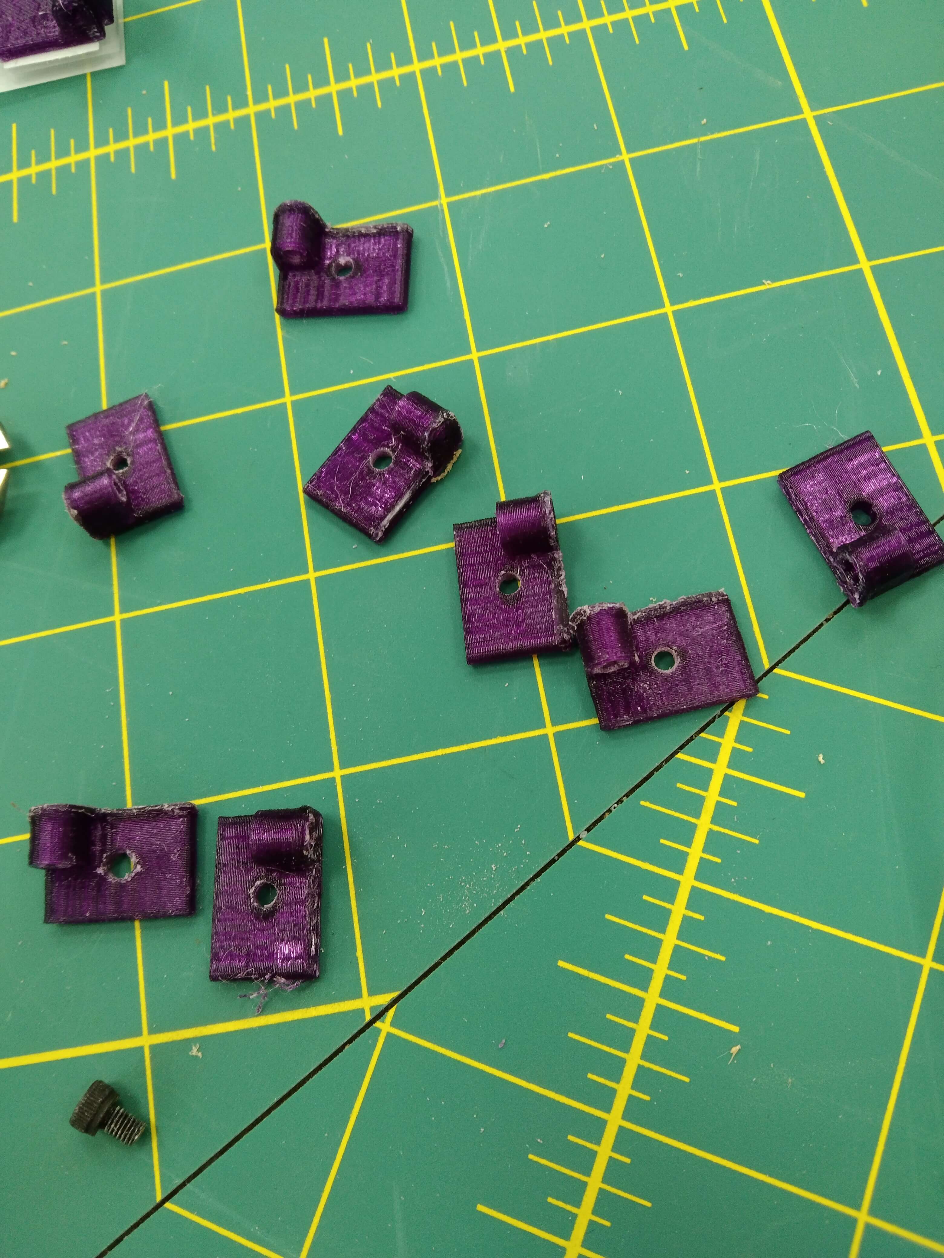
Redesigning my board + making arm 3D printed clips
╭─━━━━━━━━━━━━━━━━━━━━━━━━━━━━━━─╮
─━━━━━━━━━━━━━━━━━━━━━━━━━━━━━━─
On Tuesday-Wednesday (June 8th-9th), On the 8th I spent most of the day programming my board and I made side hinges for the arms of the glasses (to hold the bluetooth module and the battery). The programming was going fine up until a point where the ISP on my glasses became broken (after connecting it with my ribbon-cable connector too much), Mr. Carl tried to help me fix it, but at that point it was already deemed unprogrammable (not broken just unprogrammable). Though I was upset at first, I was also fine with this outcome since I planned on redesigning a board where the ISP wasn't in the way of my nose-bridge; I took this as another chance to perfect my design and make it properly now that I had experience. The next day (on the 9th) I spent time working on the PCB design. The first thing I did was swap out the ISP header with an SMD ISP header in my original PCB just so that I could add wires in-place of the ISP (I also moved some of the wires around for more convenience). In gimp I used the background (adding 1mm) of my PCB in order to make a cutout layer for the board once I flip it in the milling process (so the board will be properly reflected in the copper). I first placed a copper board into the corners of the jigs (so the board would be lined up properly), milled out the cutout for the board, and when it finished cutting I kept it in place for the milling process. Once I milled on one half I took out the board carefully, rolled the tape off and started milling on the other side of the board. When the milling machine finished cutting the traces I started the outline and took out the board once it finished. I'm way happier with the result of this board (although the via holes still dont line up exactly its a minor thing for me) the board also needed to be cut using an exacto knife (for the places that didn't have deep cuts) and poked through the via holes to ensure they were open.
╰─━━━━━━━━━━━━━━━━━━━━━━━━━━━━━━─╯
Soldering, Programming, and assembling my project
Printing cable clips, testing flash sequences, and laser etching into the arms
╭─━━━━━━━━━━━━━━━━━━━━━━━━━━━━━━─╮
─━━━━━━━━━━━━━━━━━━━━━━━━━━━━━━─
On Thursday (June 10th), I spent the day soldering my newly cut double-sided PCB. When I soldered my first double-sided board I had a bunch of difficulties soldering in the via holes, but I came up with a soldering method where I wrap the wire around the board as I solder (which made it much easier). I also had an issue where I would get solder on the sides (since they have big spaces) so I taped up the blank areas so no solder would get on the sides. Once I finished soldering the rainbow-ribbon wire cable the soldering process was a success so I immediately went to program the board, but for some reason I was having issues with the blue LED. At first I thought it was a programming issue but I had to go back and check my traces with a multimeter and it turns out the LED was working properly but the trace for the blue LED (which was underneath an LED) was severed right where we wouldn't of been able to see it! At first I tried using a basic wire to solder a custom trace but it was too thick underneath the LED. So I had to use a thinner wire which actually worked out amazingly (I can't even tell that its a wire from the image personally!). After fixing the LED issues I had I was able to successfully reprogram my RGB LED board and I could finally implement the board onto my glasses frame. I also upgraded my clips and added an upper-clip area so it could hold the rainbow-ribbon wire on my PCB. I also got the chance to laser cut another arm for my glasses (since they were both facing the same way) and I decided to add a very faint design of my bear on the arm (like a trademark in a way). I added side-clips onto my glasses (to hold the battery and bluetooth module) and did a mini-photoshoot for my glasses!
╰─━━━━━━━━━━━━━━━━━━━━━━━━━━━━━━─╯
Incorporating last minute bluetooth
╭─━━━━━━━━━━━━━━━━━━━━━━━━━━━━━━─╮
─━━━━━━━━━━━━━━━━━━━━━━━━━━━━━━─
On Sunday (June 13th, a day before my presentation!), I decided to finally incorporate the bluetooth module. I first designed a bluetoothie board on KiCad, milled and soldered it. I took my bluetooth module and unsoldered the ISP on the board so I could swap it out with the bluetoothie board I made (this part was really satisfying to do). After soldering the bluetoothie board onto the bluetooth module I connected the bluetoothie ISP and the rainbow-ribbon cable together. Once they were connected I connected them all to my FabTiny ISP and opened my old code. In order to incorporate the bluetooth module into my code I added a BTserial function which refers to the bluetooth module. The main purpose for the BTserial function I've created is so the RGB can be manually changed based on their values, starting off at 0 for the number and color until a value is changed. Once I uploaded the code I went onto my phone for adding the bluetooth module onto my phone. I first went into the settings and then the bluetooth settings. I saw an available device named "HC06" which was my bluetooth module and selected it (I renamed them to be cicely's glasses). I had to download this app called "Serial Bluetooth Terminal" in order to control my bluetooth module. Once I downloaded the app I went to devices (in the side menu) and selected my "Bluetooth Classic" device which was my bluetooth module. Once I connected to the app I was able to insert color values and combinations within the app to change the color of my glasses!
╰─━━━━━━━━━━━━━━━━━━━━━━━━━━━━━━─╯
╭─━━━━━━━━━━━━━━━━━━━━━━━━━━━━━━─╮
You can see my final project presentation and slide here.
╰─━━━━━━━━━━━━━━━━━━━━━━━━━━━━━━─╯
╭─━━━━━━━━━━━━━━━━━━━━━━━━━━━━━━─╮
You can download my L.E.Glasses board + gimp files here.
You can download my glasses frames + arms, hinges, and clips here.