ToDo This week
- Model my final project idea in multiple ways, 2D, 3D, rendered, animated, etc. ✅
- Experiment with 2D tools for raster and vector drawing. ✅
- Experiment with 3D tools for parametric modeling, rendering, and animation. ✅
Tools to try
2D
Gimp, raster graphics ✅
InkScape, vector graphics ✅
3D
xDesign, parametric modeling ✅
Fusion 360, parametric modeling ✅
FreeCAD, parametric modeling ✅
Blender, rendering and animation ✅
Final Project
This page documents my learning process. To see the final project models go to the Final Project Section.
A Note on Mice
I use trackpad most of the time. I’ve actually done just fine modeling in tinkerCAD and InkScape that way so far, but a real mouse is probably better. I have an Apple “Magic Mouse”. It was free, but it’s garbage for modeling, and just about everything else. I pulled out an old wired mouse but because I live in the future now where everything is usbC I need an adapter to plug it in to my laptop. I should buy a normal bluetooth mouse.
2D Graphics
I have worked in various raster graphics programs over the years but haven’t touched Gimp in a while. I was pleasantly surprised that the macOS port no longer needed an x11 environment as that was always a minor frustration running it and InkScape on mac. This whole section is likely to be a tirade on unintuitive user interface design as I had enough passing knowledge of some of these tools that I had hoped to open them up and start making things happen, only referring to tutorials and documentation when I got stuck.
Gimp
Gimp shot that down right away. I had a plan to draw a logo for my Maker Derby Hill Climb in raster graphics and then again in vector to compare the two. I couldn’t find shape drawing tools that I was looking for and when I tried to use the path tool to draw a shape I couldn’t figure out how to close the path into a polygon. I also knew that raster graphics were a low priority so I moved on. I’ll come back to this later when I have extra time.
InkScape
After most of the below 3D modeling was done I came back to 2D graphics but decided to start with InkScape which I am already familiar with. I had an idea for a logo for the Maker Derby Hill Climb. I wanted to draw a curve that would be a representation of the track and have the words Maker Derby Hill Climb wrap around it. I also wanted to incorporate a checkered flag in some way to show that it was a race. I started with the Bezier Curves tool to draw the track. Then added Text. I knew it was possilbe to wrap text along a path but didn’t know how. This video was helpful along with this Stack Exchange post. I was able to use the Text -> Text to Path tool along with the text kerning options to adjust the spacing of the words nicely. For the checkered flag background I drew a rectangle, set the fill to a checkerboard pattern, and converted it from an object to a path. Once it was a path I added 3 more nodes to the top ad bottom edges, made the nodes symmetrical curves and then warped the rectangle into a waving flag shape. I saved the SVG so I can keep editing it later and exported the PNG as the working version so far.

Parametric Modeling
I wanted to evaluate a number of tools to see what was going to work best for me. I also kept in mind what I would want to keep working in after Fab Academy. I’m considering ease of use, capabilities, availability of documentation and tutorials, cost of use moving forward.
xDesign
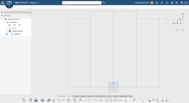
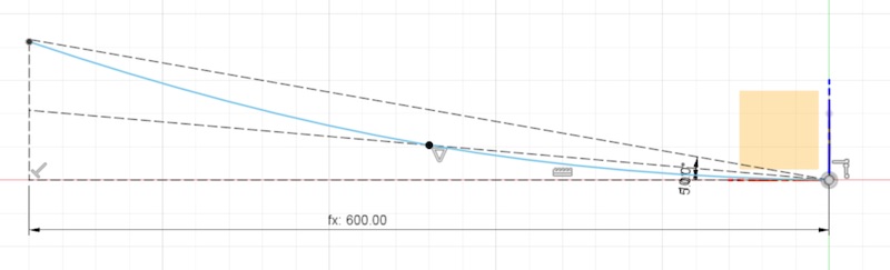
I started with xDesign because I’m working at the Desault Systemes node and I have access to the best resources available for it. We were given accounts, the web interface was a bit weird and I still don’t quite understand the navigation scheme. I was worried from the start when the registration confirmation email said “you should bookmark the URL of the app because it’s hard to find”. This doesn’t bode well for good UI. We were also pointed to the build in training modules which I tried but after the second one I tried was a video narrated by a screen reader voice to text program that I couldn’t fast forward or skip through I gave up on the training. I tried to play around with the interface. I still don’t know the commands to pan or orbit around the workspace. This should be easy. I made a little sketch. I’m still learning about constraints and what it takes for a sketch to be fully constrained. Everything needs to be fixed in space (to the origin or some other geometry), and defined by a dimension or constrained to something that has a dimension. A simple sketch of the Maker Derby Track profile:
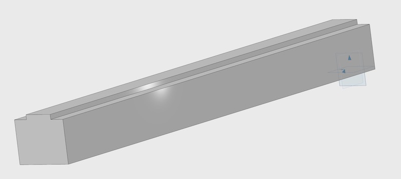
Once I had a simple sketch I was able to extrude it into a 3D part. I wasn’t able to figure out how to make the four sections of the sketch into four separate bodies. They will be assembled together eventually but they’ll be made of 4 pieces of plywood so I wanted to model them separately to make exporting the profile easier when it comes to CNC machining.
At this point I was far enough into xDesign that I felt I had a feel for the tools and the documentation available and wasn’t thrilled with what I’d found. I tried to start this a day earlier when I needed a quick 3D printed part and though I would use it to see how quick it was to learn xDesign. I got about 5 minutes into the process and when it took more than a minute of loading screen to save my initial sketch I bailed out and made the part I needed in tinkerCAD in about 10 minutes. I also still don’t know where to define parameters in xDesign.
Verdict
| Category | Score | Details |
|---|---|---|
| Ease of use: | Medium | Not super intuitive, but not terrible. |
| Capabilities: | Very High | Clearly extremely powerful. |
| Documentation and Tutorials: | Low | Documentation provided was functional but I can’t actually see myself sitting through it. Felt too much like corporate training, because that’s what it was. Independent tutorials seem few and far between. |
| Cost: | If you have to ask you can’t afford it? | I can’t actually find how much this software would cost after my educational usage ends. That’s not a good sign. I saw one news article that said $190/month. Definitely targeted towards the corporate user. |
Verdict: Keep Looking
Open Questions
There’s a lot of terminology that’s been under defined in the documentation I’ve used so far. I want to know a bit more about what making something fully constrained means and what steps I can take to make something from unconstrained to fully constrained. I also don’t fully know the different between a part, component, body, or feature. Some of these terms are application specific and some are not. Most of the documentation I’ve seen so far doesn’t do a good job explaining which of these terms are industry standards and which are application specific.
Fusion 360
I had played with Fusion a bit for class projects but never enough to really know what I was doing. I just poked at it until I either got the result I wanted to got frustrated and gave up. I started with the Fusion 360 for Absolute Beginners video series from Lars Christensen on Youtube. This also points to a good explanation of how Fusion brakes up some of the terminology I was just questioning. A component is a Fusion 360 file. It contains and origin, bodies which are 3D geometry, sketches which are 2D geometry, and other components as assemblies. Components can have names, joints (for assemblies), part numbers, and descriptions. Bodies can become components which can nest into assemblies. Always start a new part by creating a component to contain it. This captures the history which can be helpful to change things later.
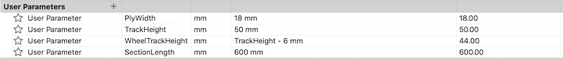
Using the youtube tutorial and Greg’s quick demo in our section meeting I started with my sketch. I defined a few parameters for my track section.
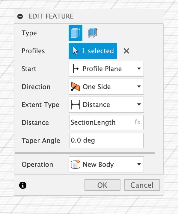
With this I was quickly able to replicate the sketch I had made in xDesign and then take it a few steps further. Lar’s tutorial was easy to follow and I had it play in the background as I worked. I wasn’t following his steps verbatim but was paying attention for useful tips. Once I had the 2D sketch and extruded into a 3D part I figured out in fusion that it was easy to make each rectangle of the sketch a separate body by selecting the New Body options in the extrude menu instead of the default Join.
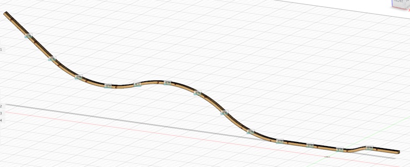
Next I wanted to make a curved section of track. The flat track was simple, but the goal is to have several different profiles which could be used interchangeably to build different track layouts. I wanted a section that curved up, one that curved down, and after making those I realized I wanted an S curve that can do a small level change but stays parallel to the previous section end. I created 2D sketches on a perpendicular plane with some construction lines to define the curves. I still don’t know what I should be doing differently to fully constrain the curve. I dimensioned the horizontal construction line with my track section length parameter and defined the angle between the horizontal and the two sloping lines. I then created a spline from the origin, to the midpoint of the lower line to the intersection of the higher slope and the vertical line. I suspect there is something about splines that needs to be fixed because the curve handles are still adjustable but I just gave the curve the fixed constraint and moved on.
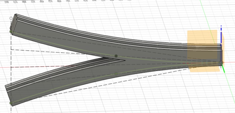
I swept my first sketch along that curve to create a track section which will mate perfectly with any other section. When I finished the Up curve section pictured above I tried to use the mirror tool to reflect the curve around the top construction line to create the down curve but I found that my curve wasn’t quite right. It didn’t meet the line I wanted to mirror about because as you can see in the sketch the vertical line doesn’t extent past the top sloped line. The curve had in fact snapped to the top of the vertical line and no the intersection of the vertical and horizontal. I was able to fix the curve and go back in the history and redefine the sweeps to use the fixed curve. I had tried to create the curves for the different track segments all in one sketch but when I tried to do that I noticed my original up curved segment updated itself with the new down curved sweep. I couldn’t find a way to uncouple the curves in the sketch so I just made a new sketch for each of the different track segments. They all share the original track profile sketch.
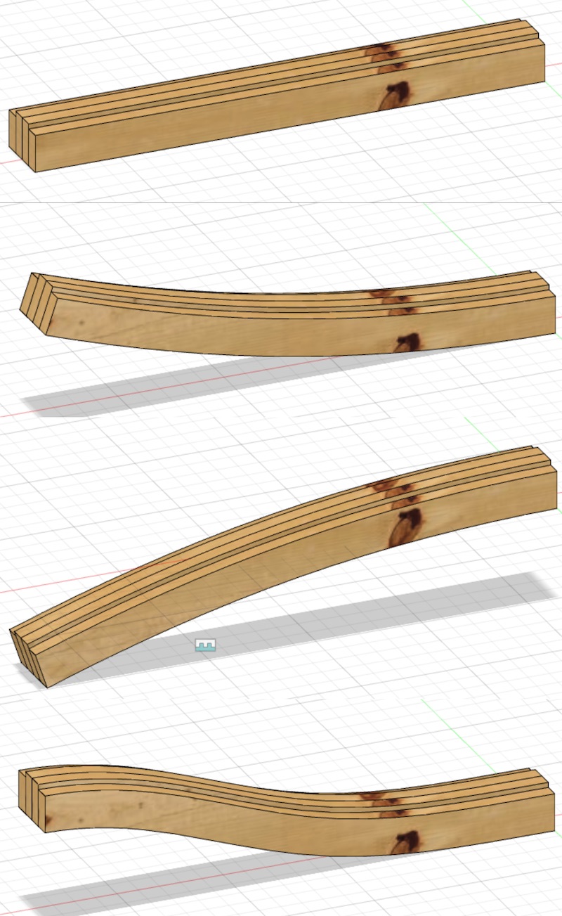
I also found when I made the sketch for the S curve section that by using the tangent constraint for both ends of the curve with a horizontal construction line that fully constrained the line so I didn’t need to use the fixed constraint. I now had 4 different track segments. Flat, Up Curve, Down Curve, and S Curve. I played with the appearance menu to get them to look like wood.
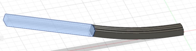
Next I wanted to assemble these pieces into an example track layout. I was hoping there was a way to create duplicates of each segment without just using the move/copy command a bunch of times but that seemed to be the thing to do. If there’s a better way to make an assembly of a modular system let me know. I left my original 4 sections alone as they’ll be the base for everything and I still have some work to add bolt holes and figure out the system for joining the sections together. But that should auto propagate to the copies once I add those features. I copied the first section of track and moved it in the workspace out of the way. Then I copied the next section and created a joint from the end face of one section to the start face of the next.
This was a bit tedious to navigate around the view and move and copy the original segments but I made it work. I eventually copied 14 sections of track so my example track would be about 30 feet long. I hope to find an easier way to combine these sections into larger components for duplicating them because the goal is to create 2-4 parallel lanes of the same track. Then I need to design the support structure that holds the lanes together and keeps them from falling over as the hill climbs. I have a stretch goal to create a horizontal curve so the track can go around corners not just up and down but I will leave that until after I have fabricated these parts and I’m more familiar with the capabilities of the CNC router.
Animation
Once I had the track built I wanted to try to make a simple animation of a car rolling on the track. I modeled a simple car with just a simple body and two axels. I used cylindrical joints to allow the wheels and axels to spin in their mounts. I was hoping to then be able to join the car to the track and have it slide along. Unfortunately there is a limitation on the slider joint type that it can only work along a single axis and cannot follow a curved path. I instead used Fusion 360’s animation tools to place some keyframes of the car moving along the track and let it interpolate the motion from one to the next. This results in the car floating off the ground and then passing through the ground a bit but it gets the idea across.
Verdict
| Category | Score | Details |
|---|---|---|
| Ease of use: | Medium+ | Most things were fairly intuitive. Still some strange behavior I don’t understand like the right click and drag actions. |
| Capabilities: | Very High | Clearly extremely powerful. |
| Documentation and Tutorials: | High | Tons of third party tutorials and resources. I’ve been hearing about fusion as the go to maker software for a while so there is a lot of community support out there. I haven’t had to look at the official docs yet. |
| Cost: | Medium | $500/yr for the full version. Autodesk made a lot of people angry when they started restricting the maker license Fall 2020. I can probably make do with the free version restrictions if that sticks around, and if I’m actually making things that money then I should be able to afford a license. |
Verdict: I think this is the right balance of ease of use and versatility for what I need right now.
FreeCAD
I poked around with FreeCAD a bit but didn’t have high hopes for choosing it. While it does have the benefit of being free, the UI is a bit too clunky for me to want to fight through it. A fellow student linked to a good quick start that he had written. I used that to open up the program and make a new sketch. I tried to sketch the same track profile as I had made in my previous two CAD explorations. I quickly ran into trouble getting a point coincident with the origin. There didn’t seem to be a co-linear constraint so I had to use coincident on the endpoints of the lines. I was confused that those constraints we not automatically defined because when drawing a rectangle I clicked directly on the origin for the first rectangle and on the shared point for the second rectangle, bug I guess freeCAD wants you to declare those relationships explicitly. I drew my two rectangles and then wanted to mirror them. I quickly found the freeCAD documentation told me that there was a mirror tool but it would create a separate sketch instead of mirroring in the same sketch. It took me far too long to find the mirror option in the menus despite the documentation listing where it was. At this point I decided to pass on freeCAD. I closed it and then realized I should open it back up and get some screenshots for this document. I attempted to quickly recreate this sketch for that purpose and managed to crash the program. Another strike against it.
Verdict
| Category | Score | Details |
|---|---|---|
| Ease of use: | Low | Not super intuitive, makes no assumptions for you which is more annoying than not. I can see it being plenty powerful to someone who’s willing to climb the learning curve but I’d prefer some more visual |
| Capabilities: | High | It is clearly capable of a lot if you put the work into it. |
| Documentation and Tutorials: | Medium | Documentation seemed above average for an open source project. Independent tutorials seem abundant. |
| Cost: | Free! | Open source FTW. |
Verdict: Maybe a future go to if I have more time or Fusion becomes too expensive.
Rendering, Simulation, and animation
Blender
I wanted to dabble in Blender in addition to the parametric tools above to see what its Rendering, Simulation, and Animation tools could do. I learned blender from a recording of an online class taugth by my friend Ferdi. He spent a lot of time talking about history and stories of Blender’s development but the important things are some shortcuts. To Pan the view hold shift and click and drag the middle mouse button. To Orbit the view click and drag the middle mouse button. To Zoom scroll the mouse wheel. The next most important tools are the G, S, R keys. These are for Grab (move), Scale, and Rotate. You can combine these keys with the X,Y,Z keys to restrict the movement to an axis. You can then also type in a value and press enter for an exact transformations. After polking around with those tools, I took the .stl file of the track from Fusion and imported it into Blender. I ran into my first issue here because the track model is 30 feet long I couldn’t see it in Blender. I zoomed out and panned around and could only see a small section. I guess there’s something equivalent to render distance in video games that reduces the computational load when viewing large models. As I was just creating visuals the size wasn’t important. I just scaled the track down.
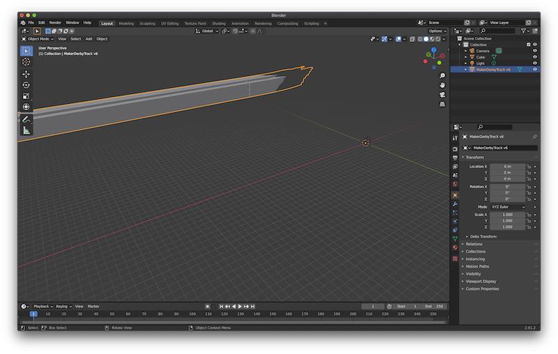
I added an array modifier to the track to create a 4 lane version. Then I wanted to play with the physics simulation to see if I could get something to roll down the track. I imported the .stl file of the car I made in fusion but I couldn’t get it to play nice with the physics engine. I kept falling straight through the track. I made a simple axle with two wheels to fit on the track and followed the simple instructions from Neil’s blender physics video from lecture this week. This resulted in the screen capture below. This is cool. But my home kit CNC router just arrive so I’m going to assemble that now.