How to make (almost) anything.
Week 11. Molding and casting
Work done in the Lab under the guidance of my remote Instructor to accomplish the weekly assignments.
This week I designed and milled a soap mold.
My weekly schedule:
| Wednesday, April 14 | Thursday, April 15 | Friday, April 16 | Saturday, April 17 | Sunday, April 18 | Monday, April 19 | Tuesday, April 20 |
| Global class | Review of safety data sheets for molding materials | Local review | Mold design | - | Mold milling |
Mold milling Mold seal Silicone casting Soap casting |
Group assignment
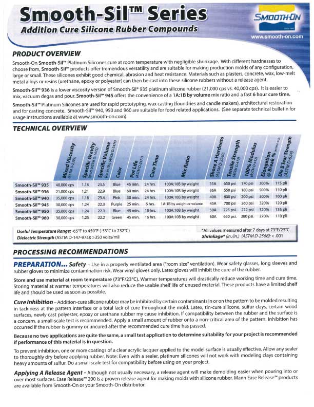
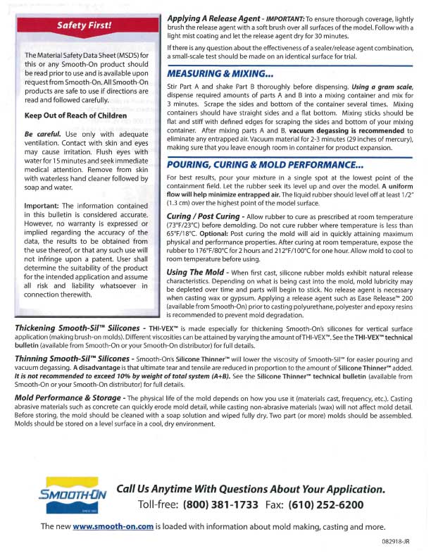
This week we reviewed the safety data sheets for each of our molding and casting materials, then made and compared test casts with each of them. You can read it there.
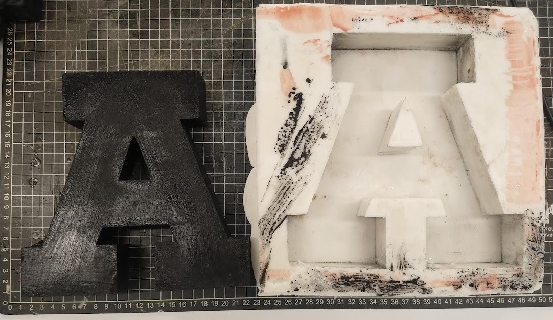
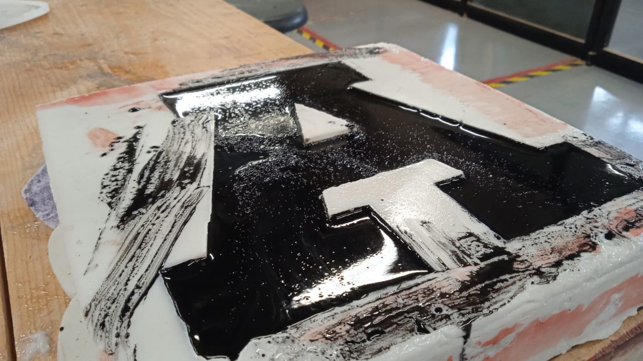
For our test castings we used a wooden letter A to make a silicone mold and then poured some inked resin in to get a replica of the original part.
The ratio for this silicone and diluent was 1:0.25 and 2% of catalyst, so we used 1 kg of silicone, 250 gr of diluent and 20 gr of catalyst.
The casting did not gave us problems but the silicone mold copied all the imperfections of the original piece (the sanding marks and a couple of fractures in the wood), so we decided that for our next test the piece to be replicated should have a resin coating to have its faces as smooth as possible. We also learned that polyester resin generates a lot of heat when it hardens, so its faces can be marked by the air bubbles that come out, and the final dimensions are reduced a bit due to the contraction that occurs.
The ratio for the resin and catalyst was 1:0.02 so we used 1 kg of poliester resin and 20 gr of catalyst.
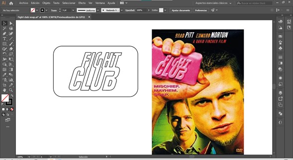
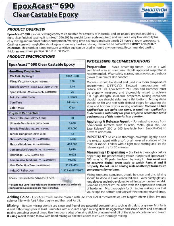
Fight club is one of my favorite movies and I think this assignment is perfect to honor this masterpiece: I'll make a soap mold. I started by drawing the logo in Illustrator from the cover of the film.
I exported the strokes in DXF and made extrusions in Rhino taking the dimensions of a commercial soap bar as an example.
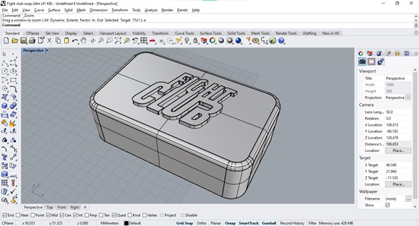
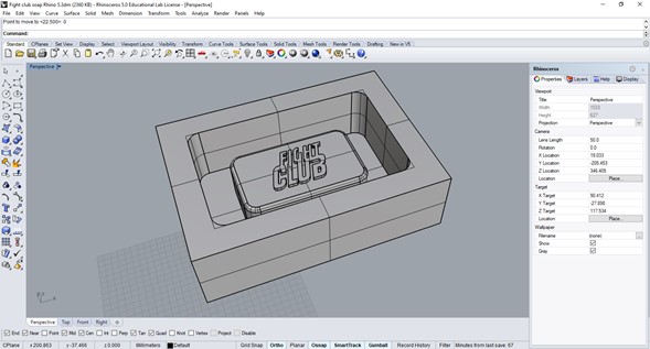
With a couple of boxes and Boolean operations I made the mold that will be made of MDF. I left enough space to be able to pour silicone to make the negative mold. To be able to unmold the resulting piece the walls of the mold must have an angle of more than 90°, so it can slide freely.
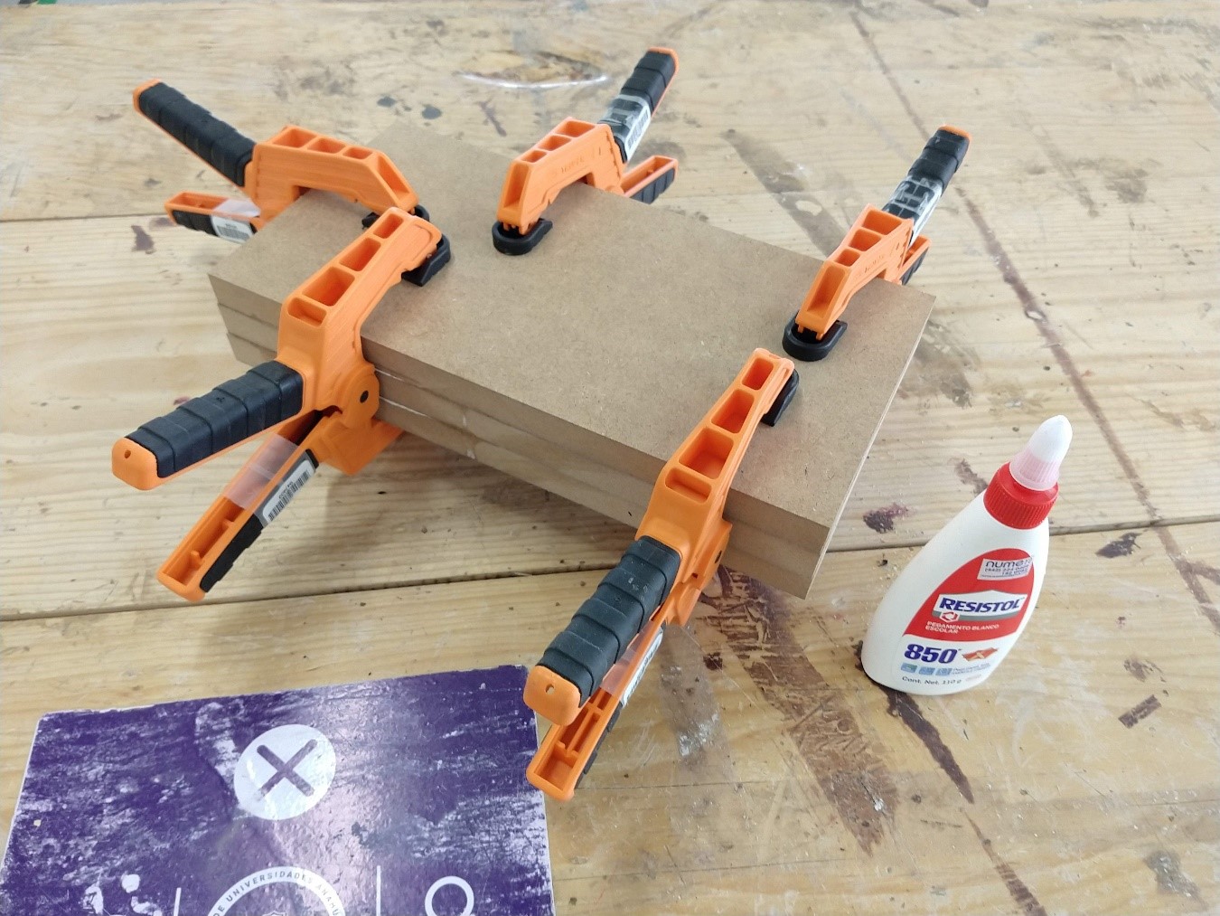
To get a 54mm stock I glued three 18mm MDF pieces together, pressed them and allowed to dry for 24 hours. It is important to use white glue and apply the pressure evenly to prevent the parts from coming off at some point during machining due to the power of the mill.
G-codes on RhinoCAM
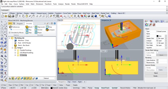
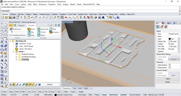
The G codes for our router are generated in V-Carve (for 2-D cuts and basic 3D engravings) and in RhinoCAM (for 2-D cuts and very complex 3-D engravings), both are powerful and simple to use, but for this exercise I preferred to use RhinoCAM as it offers a greater number of engraving parameters. Once I finished my model of the mold in Rhino I just opened the plug in.
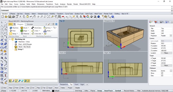
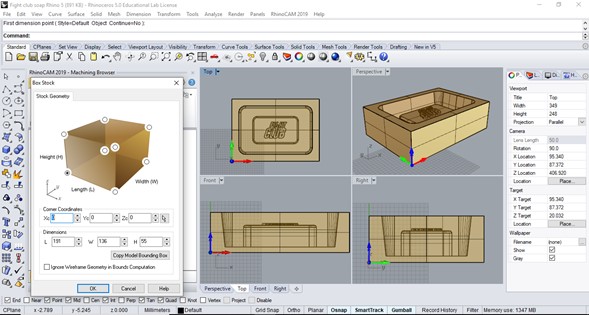
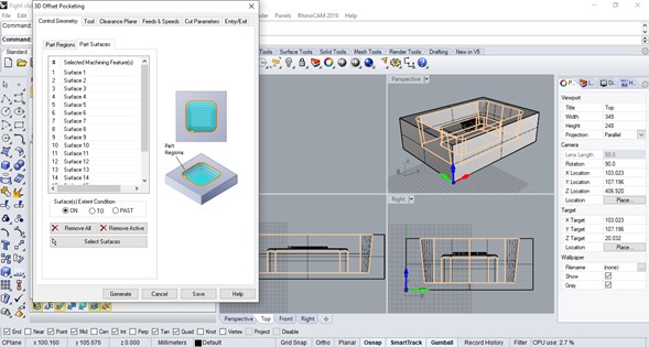
The window on the left shows all the relevant information for machining, such as the characteristics of the machine, the post processor, the material and the operations. To start working, I generated a Box stock with the same measurements of my mold by activating the option "Copy model bounding box", this avoids later problems due to incorrect dimensions or coordinates.
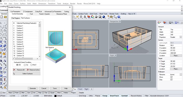
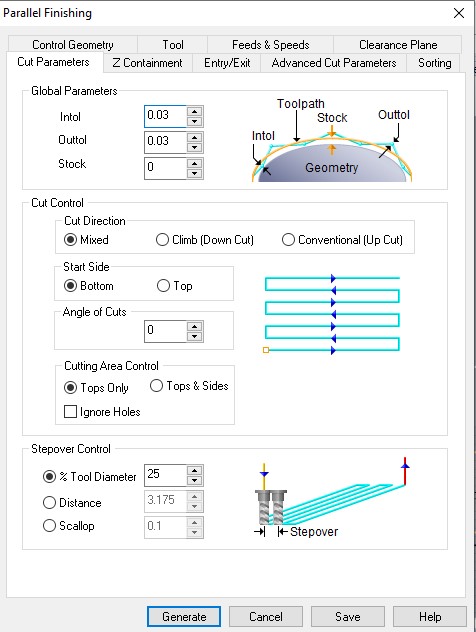
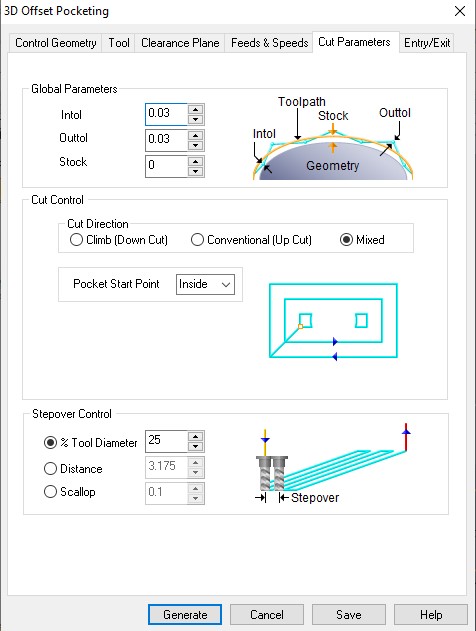
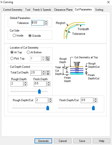
It is important to establish a correct order of operations so as not to risk the milling bits, the material or even the integrity of the machine: we usually do a Roughing operation with a thick mill and a fairly high depth of cut, and then a Finishing operation with a thinner mill for good finish resolution. In this case I was able to save time through the first operation which was a Parallel finishing just by selecting all the interior faces of the model. The tool selected was a ¼ inch straight mill because most of the faces are straight, and that size because a thicker one could endanger the inside part because there is only 18 mm between the outside wall and the inside wall .
To indicate the parts to be machined I activated the Control geometry tab and selected all the interior faces of the central part in the Part surfaces section.
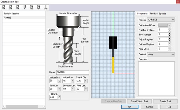
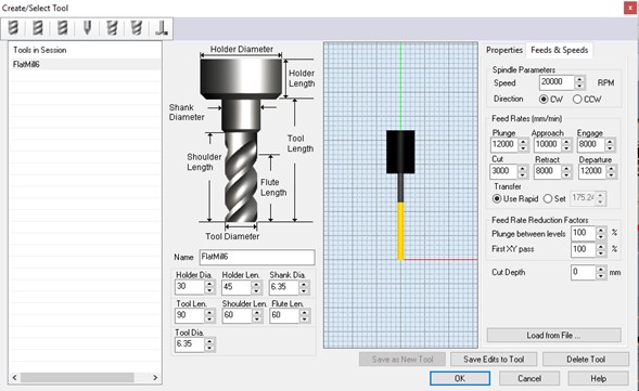
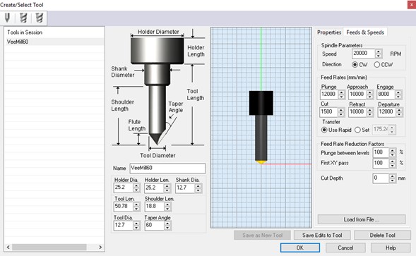
I created different tool profiles according to the ones I had available: ball mill, flat mill and v-mill.
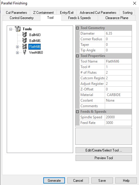
The first operation was configured using the ¼ ”flat mill, in the first tab the most important information is the diameter of the mill, the tool length and the tool number (if different tools are configured, they must all be assigned as tool # 1 so as not to create conflicts in the control of the router).
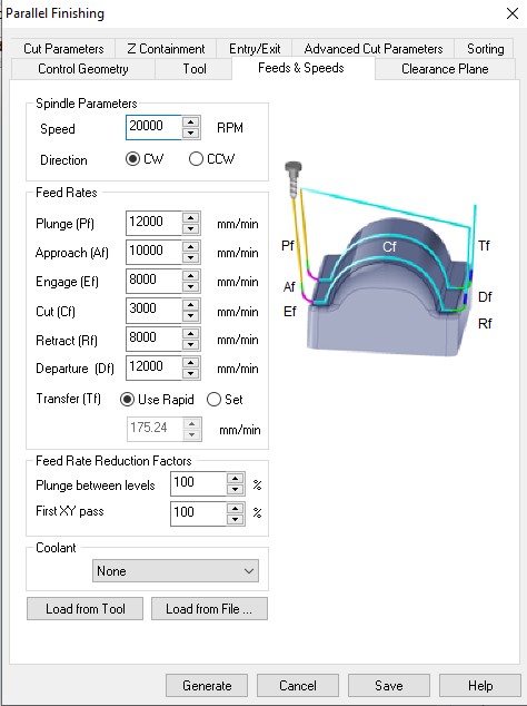
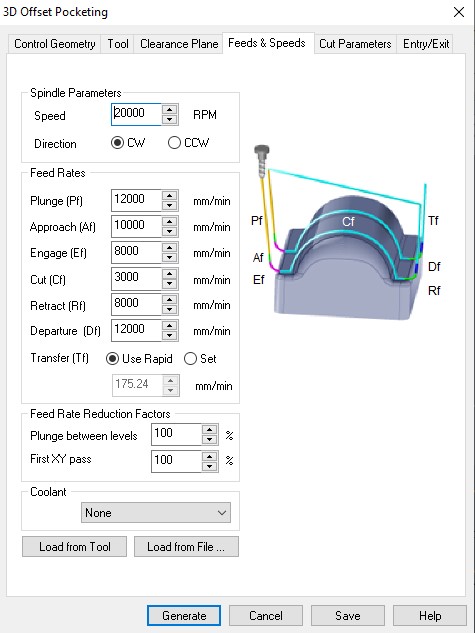
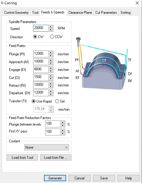
The second tab is the most delicate as it contains all the information about the mill speeds. The revolutions (RPM) are higher as the diameter of the tool is reduced, this router has a maximum speed of 24,000 RPM and for the ¼” mill we use 20,000 RPM (it can be reduced proportionally with the cutting speed, taking effect on chip size), the other values in the table are our average reference values for this mill size. Cuttin' it close's Youtube channel has a good video on this topic.

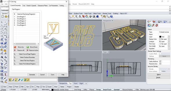
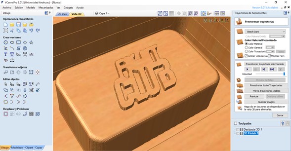
I missed a very important detail in my design: the size of the letters was too small for the mills we have currently in the laboratory so my only option was to use a V-mill in the hope that the angle would not affect the readability of the text.
The simulation didn't look too bad, the letters were thickened so the appearance changed, but I was hoping it could be corrected manually.
I did a quick test in V-carve hoping that some of its presets would result in a higher resolution in the letter engraving, but it looked even worse than in RhinoCAM.
Machining
The process was very similar to what I did in the Computer controlled machining week, but in this case I secured my material inside a wooden frame screwed on all four sides to the table.
The machining took about three hours in total, much less time than the simulation calculated in RhinoCAM (nine hours), so we don't take that data very seriously when cutting or engraving here.
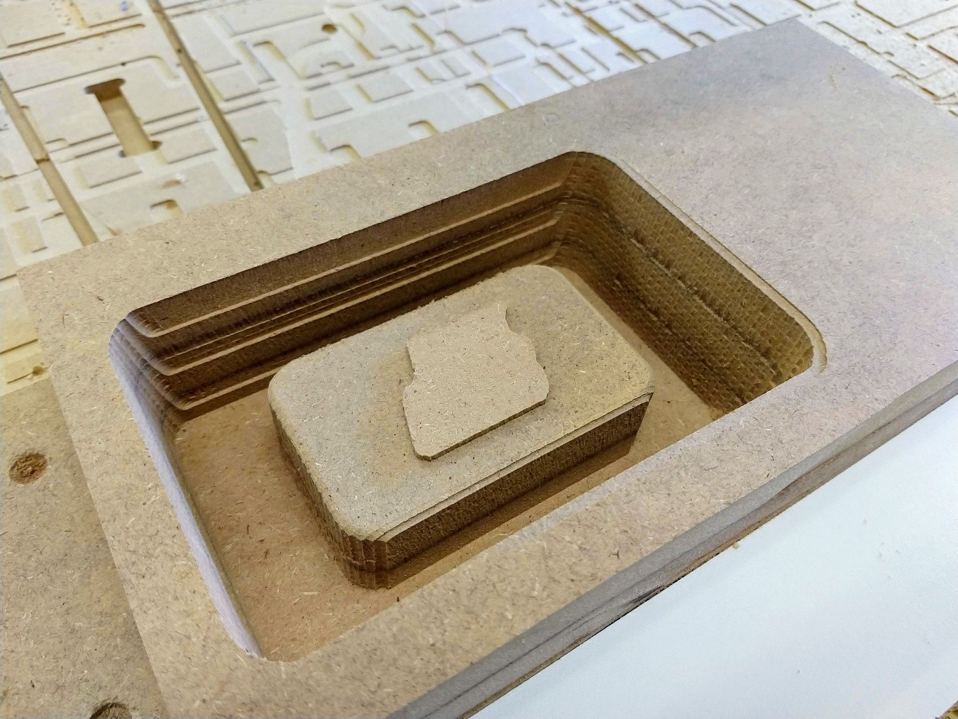
At the end of the roughing operation ("Horizontal finishing"), the piece looked like this:
Then I did the Pocketing operation just to remove the imperfections on the curves, and the V-carving for the letters. At the end of the operation the letters were not distinguished correctly, so I took the risk of repeating the operation but lowering the mill by 0.5 millimeter so that it penetrated more and the text had a greater definition.
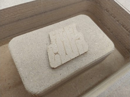
I repeated the operation once again and the text looked better, maybe a last repetition would have given it more definition but the tip of the mill was already marking the upper face of the mold so I preferred to leave it that way.
I applied wood sealer and let it dry, this in order to close the pores of the material to be able to apply release agent and silicone without risk of sticking to the MDF.
In 24 hours I will make the silicone casting...
In the meantime I checked the safety sheets for silicone and epoxy resin for the group assignment.
When the wood sealer was dry we did a test with water to see that it did not leak out or wet the material, and it was a success.
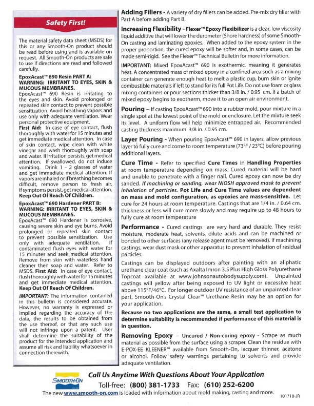
These are the materials we used: wood sealer, two-component silicone and release agent.
To prepare the silicone we used a scale, it is necessary to take care of the proportion between components so that the result is optimal, for the Smooth-Sil 936 the ratio is 1:10.
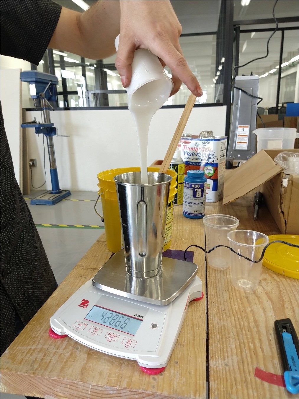
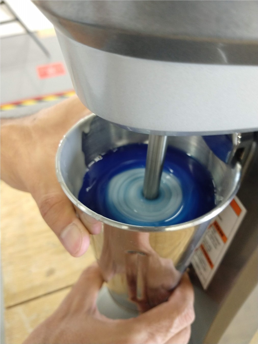
We pour everything into a blender cup and mix very carefully so as not to generate bubbles but without taking too long to be able to calmly pour the mix into the mold.
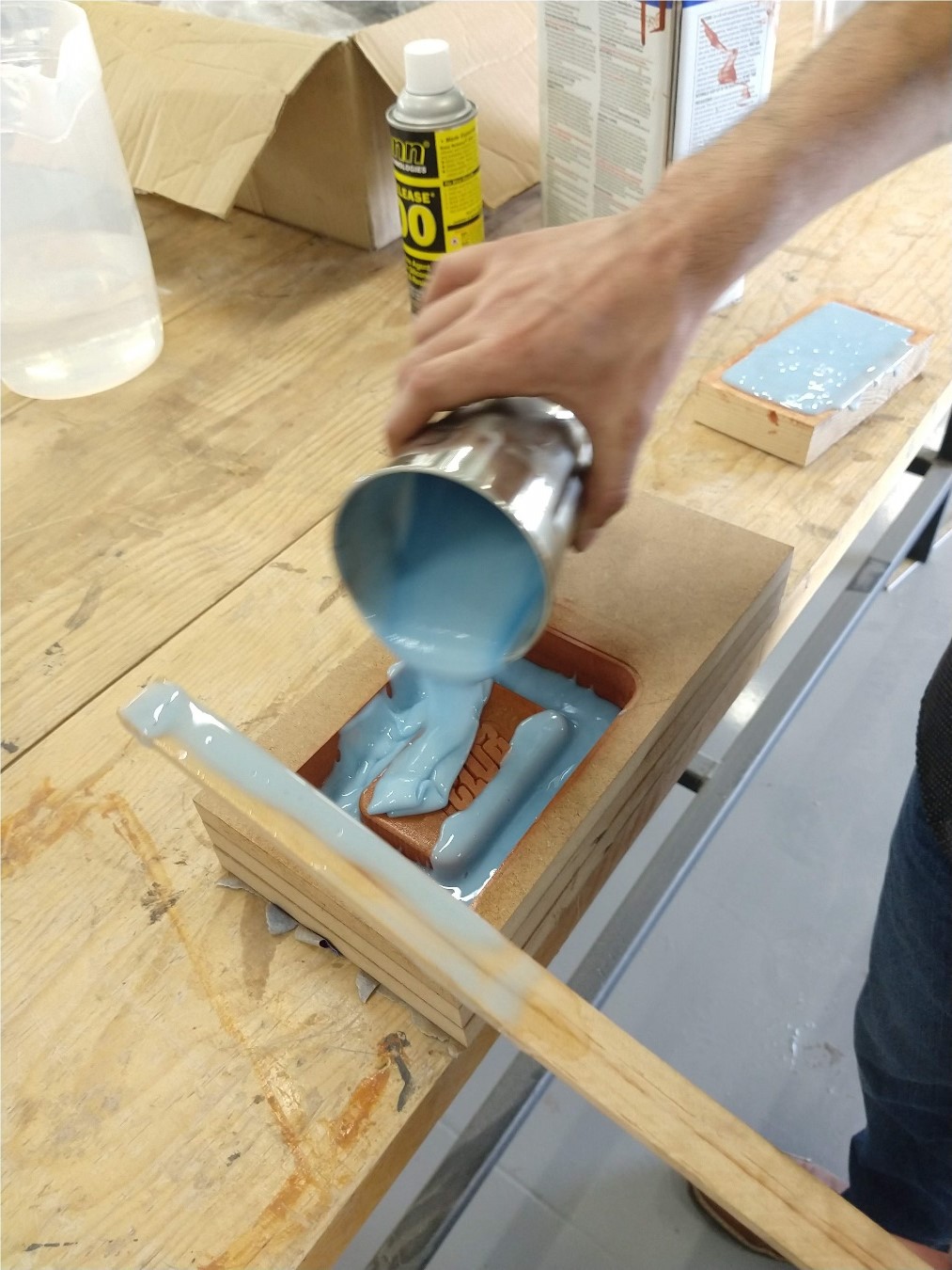
Carefully pouring on the mold.
The silicone ready to cure.
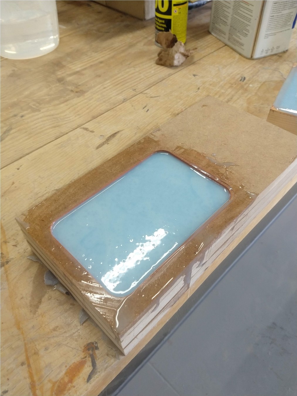
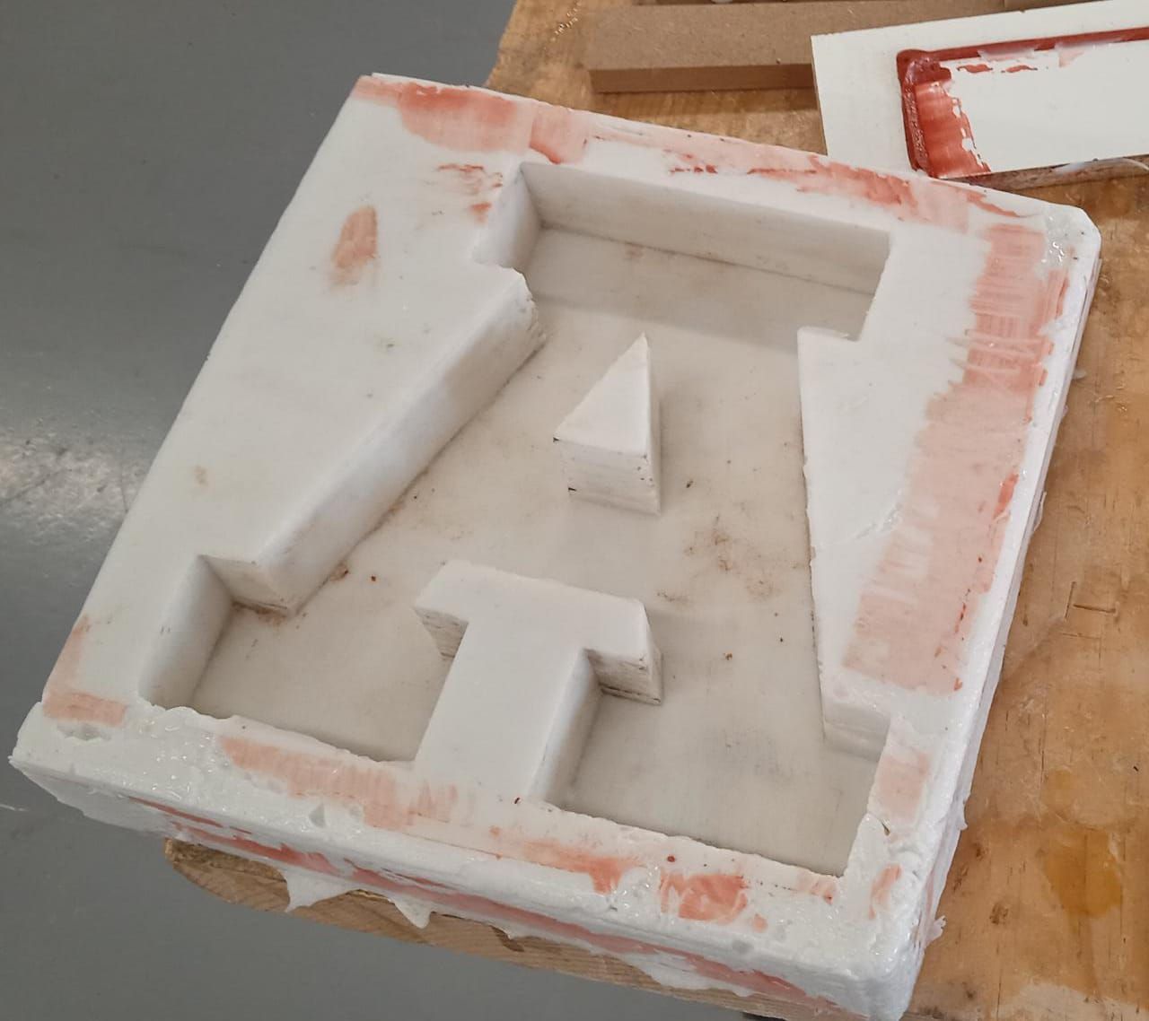
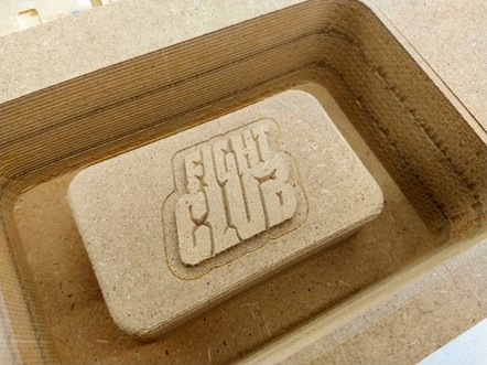
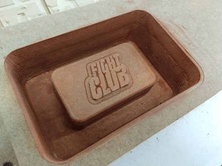
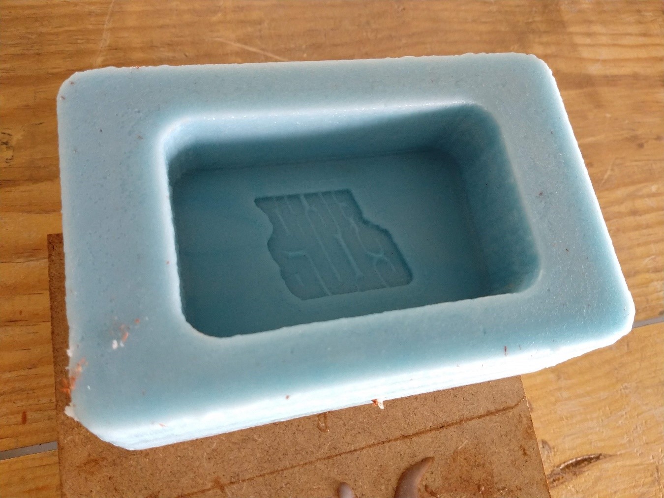
After 24 hours curing the mold was done.
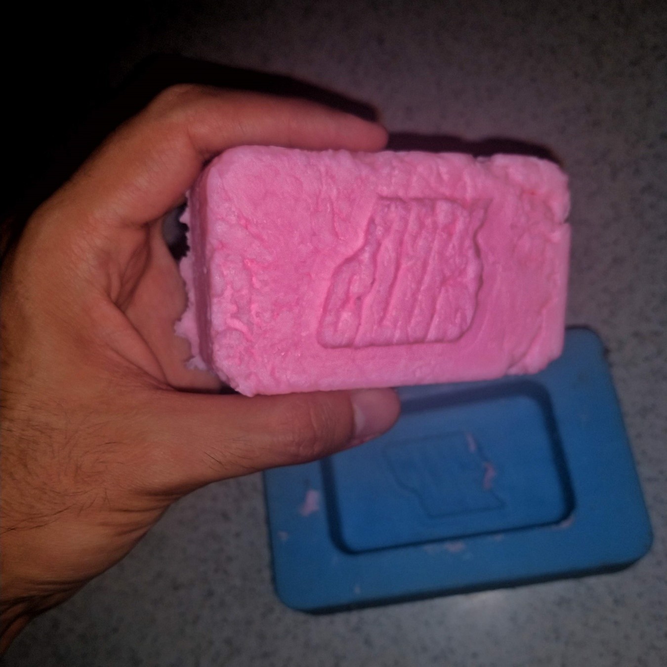
At home I slowly melted a bath soap, it was difficult because at a high temperature it burned and at a low temperature it did not melt, so I had to find a middle ground. The texture was not totally viscous, some lumps remained and seriously affected the quality of the final product, but I had fun making this. Maybe I will try again later with raw material.
Files
You can download the 3D model of the mold here.
|
For this assignment I:
|