How to make (almost) anything.
Week 7. Computer-Controlled Machining
Work done in the Lab under the guidance of my remote Instructor to accomplish the weekly assignments.
This week I made a modular cabinet as a test on the CNC router.
My weekly schedule:
| Wednesday, March 10 | Thursday, March 11 | Friday, March 12 | Saturday, March 13 | Sunday, March 14 | Monday, March 15 | Tuesday, March 16 |
| Global class | Global class review |
Speeds and feeds reading Drills & mills reading |
Cabinet design Global open time |
- |
Machines recitation Cabinet design |
Cut Upload documentation |
Group assignment
This week we did our lab's safety training, testing runout, alignment, speeds, feeds, materials, and toolpaths for our machine, you can read it there.
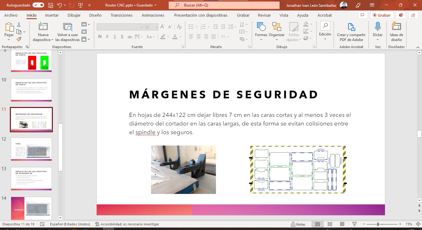
We have been working on the CNC router with the students for some time and since we have to give the same safety talk to each of them I prepared a Powerpoint presentation with the most important considerations on personal protective equipment and safety recommendations when holding the material to the table.
Design
For this assignment I decided to make a modular cabinet to be able to transport tools or equipment or even work with a laptop, my goal is to make the design and leave it ready to cut when we are in need or when we have material in stock (the quarantine has meant that not much wood is available). I took inspiration of Frontier Design modular system with more useful dimensions for our needs, rounder shapes to avoid injuries and some improvements on the joints with the help of Vaneza Caycho's work on digital joinery.
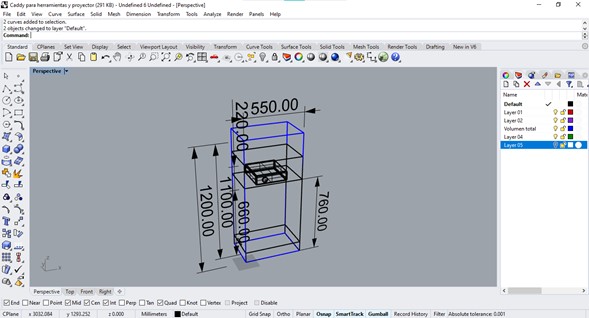
The first step was to determine the measurements considering the height at which I work comfortably at a laptop while standing, and the height at which we need the projector.
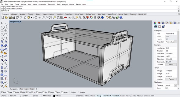
I started with the design of the base, originally it would be a simple box with joints but I read about the project that Vaneza Caycho is carrying out entitled “50 digital joints” and I found very interesting things so I decided to try assemblies similar to the Tenon with mortise.
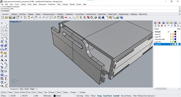
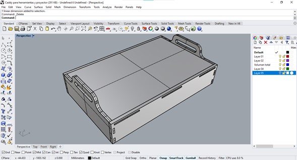
This base can be placed directly on the floor or placed on wheels to be able to move it through the laboratory. Then I made the basic module, a box with a similar shape but with adequate dimensions to place a projector without having ventilation problems.
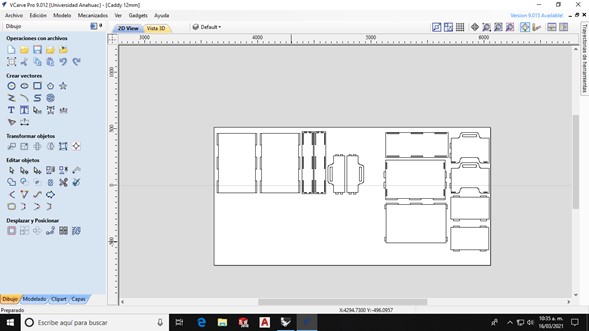
When I finished with the design of those first two pieces I proceeded to generate the cutting paths in VCarve so I exported the plans from Rhino in .DXF format. In my files for cutting I usually draw a rectangle with the measurements of my material to have a notion of how much material I need and thus make the most of it, when importing all the objects the program considers this rectangle as the measurement of the material although this can also be indicated manually when opening the file.
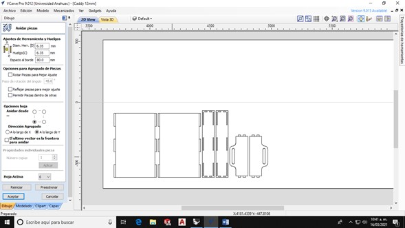
At the moment we do not have much material in stock due to cuts in the supply lines, in conditions like these it is essential to take advantage of the available material in its entirety and for this purpose VCarve has a very easy-to-use nesting tool, you just have to indicate the diameter of the tool you are going to use, the space to the next part, the point of origin of the parts and the direction in which they can be placed. My first test was with the base only so I removed the other objects before doing the nesting.
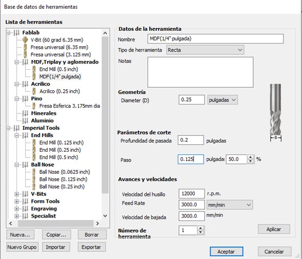
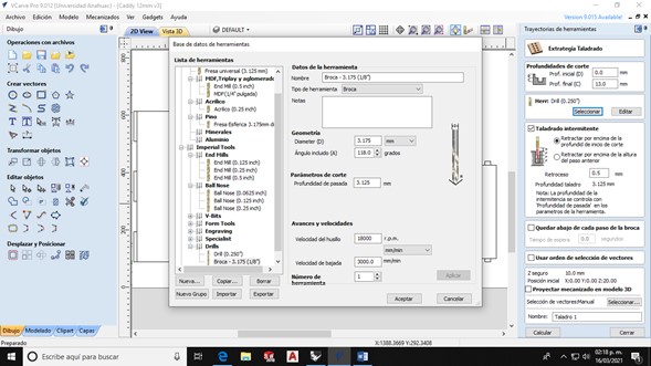
Then I configured my tools, I would have liked to use a single mill for all operations since this would translate into a shorter operating time but when entering the values of the diameter of the tool I realized a very important detail: the thickness of my slots was smaller than the diameter of the cutter I was going to use (6mm vs 6.35mm) so I would have to modify all my assemblies by increasing the thickness of these slots.
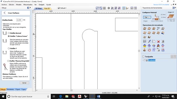
Before going back to Rhino to modify that detail I also checked if it was possible to add the fillets in VCarve so that the assemblies would work correctly and not have rounded corners that would not allow assembly. The program offers two similar options: dogbone that rounds the figures by placing semicircles in the corners, but I was not able to use them since the diameter of the cutter was greater than the thickness of the assembly; and Tbone, which places the roughing semicircles perpendicular to the cut, but they didn't help me either since they would reduce the space from the groove to the edge of the wood too much and that could cause a fracture by putting weight on that part.

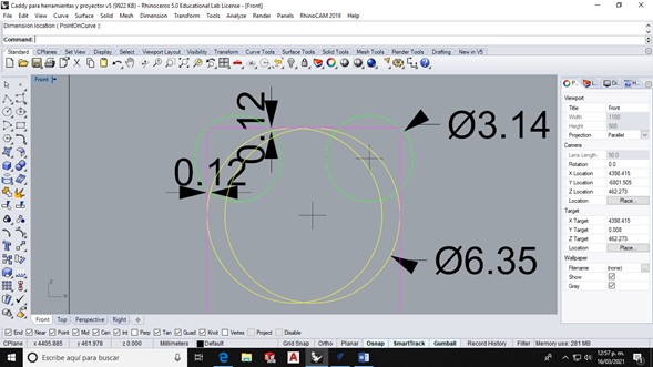
To solve this, Luis suggested making simple holes with a thin drill and then cutting the pieces with the ¼” flat mill. In the image the yellow circles indicate the thickness of the straight cutter and the green circles indicate the places where the drill will remove the imperfections.
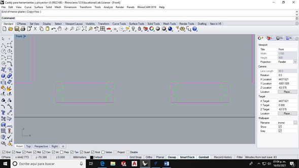
I placed these circles at each 90° angle and thickened the perforations to 7mm so that the program would not have errors due to the thickness of the mill. Working with several colors helps me to have clear references of the different elements (unfortunately I could not get VCarve to respect the colors).
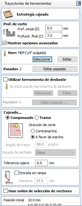
I exported my file again and configured the toolpaths like this:
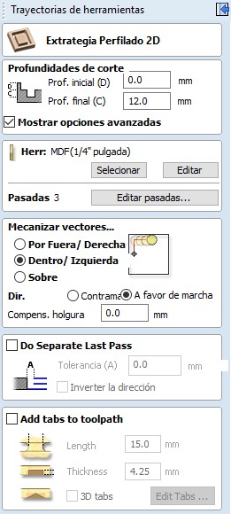
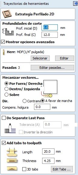
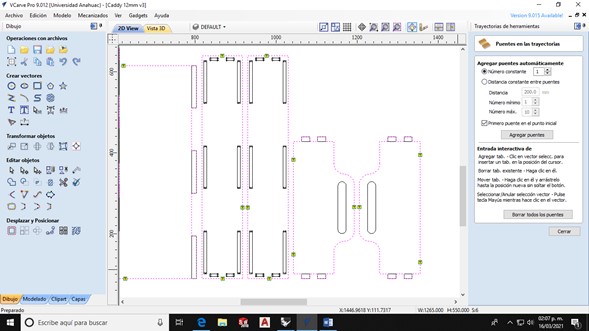
In the objects that will be cut outside the line I placed tabs so that the material would remain immobilized at the end of the cut.
I carefully reviewed the cut simulation and realized that I had not generated the drill toolpath so I added a new tool to the library.
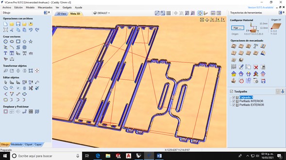
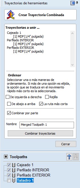
I combined the toolpaths to send a single file for the mill and another one for the drill.
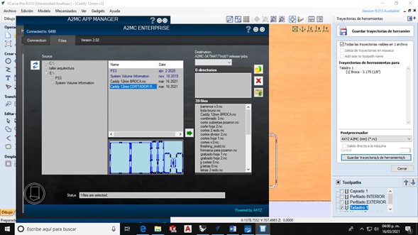
Having the two .NC files ready, I sent them to the router using A2MC app manager by clicking on the file name and sending it with the green arrow button.
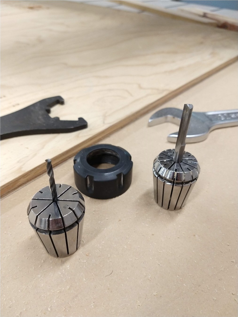
I used a 1/8" drill and a 1/4" mill.
The operation of the router is carried out with numerical codes entered in a control. The initial basic sequence is this:
- F10 Assign an origin point
- F25 Tool height sensor
- F20 Specify material thickness
And other frequently used codes are these:
- F13 Move to selected origin point
- F11 Search point of origin in list of saved points
- F42 Activate spindle
- F899 Restart the machine
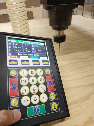
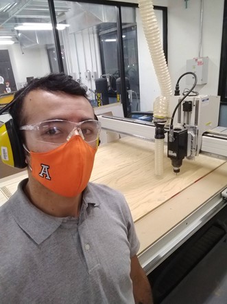
Before using the cnc router I put on the safety equipment: goggles and ear protectors.
Then I started cutting.
|
AXYZ Z7 CNC Router 12mm plywood
|
And the first piece worked fine, the joints were quite solid.

As the base worked correctly and supported a lot of weight I proceeded to cut the next part, the process for creating toolpaths and the cut was basically the same but with a larger material.

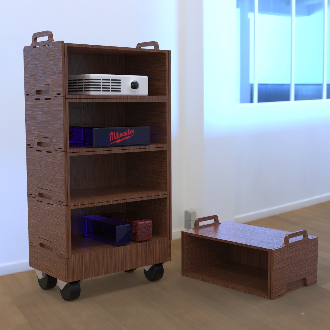
I ran out of material after this piece so I will cut the rest of the cabinet soon, but I am satisfied with the result. The complete cabinet will look like this render that I've made:
Files
You can download the editable Rhino file with the 3D model and the 2D plans here.
You can download the VCarve .CRV file here.
You can download the .DXF file here.
You can download the .NC files here.
|
For this assignment I:
|