How to make (almost) anything.
Week 05. 3D Scanning and Printing
Work done in the Lab under the guidance of my remote Instructor to accomplish the weekly assignments.
This week I made a few tests on 3D printing for my final project, I scanned me and printed the result.
My weekly schedule:
| Wednesday, February 24 | Thursday, February 25 | Friday, February 26 | Saturday, February 27 | Sunday, February 28 | Monday, March 1 | Tuesday, March 2 |
| Global class | 3D design | 3D printer characterization | Local review | 3D design |
Recitation 3D scan 3D print |
3D print Upload documentation |
Group assignment
For this group assignment we tested the design rules for our 3D printer, you can read it there.
Doing these test prints allowed me to learn some of the manufacturing limits of the printer we use the most. It is also worth mentioning that the results can be affected if we change the print settings (for example, reduce the speed on the overhangs), the nozzle (a 0.2mm one will surely be able to print thinner walls than the current 0.4mm one) and even the material (we've had retraction issues when changing filament brands), so ideally we should run these tests with every major change in our setup.
3D printing
This week I tried to develop my final project design to take advantage of the 3D printing assignment. I do not have the electronics part ready so the measurements will surely change in a few weeks depending on the size of the components, for this reason I decided to focus on the shape and ergonomics of my lamp.
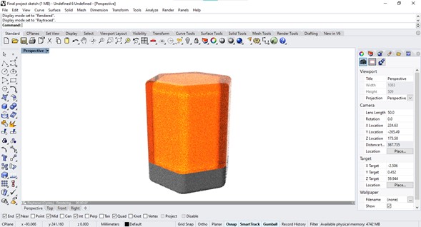
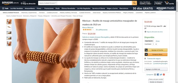
My previous design was a hexagonal geometric body, analyzing its semiotics this shape did not generate any sense of tranquility due to its straight walls and its corners. For the redesign I made a list of the activities that we normally do to relax, and what is more relaxing than a massage before going to sleep? Why not take advantage of the body of the lamp to give a gentle massage? Taking a commercial product as a reference, I developed the exterior part.
Rotating discs could be made by laser cutting or 3D printing, but one of the requirements of this assignment is to print something that cannot be made subtractively so the decision was pretty obvious.
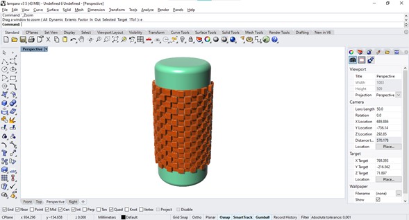
The LED strips of the lamp will be contained within a cylinder and the spinning discs will be around it, a possible problem that I will face is the partial cancellation of the light due to the infill density of all the pieces, so I will use transparent filament, resin clear or in the worst case laser cut acrylic.
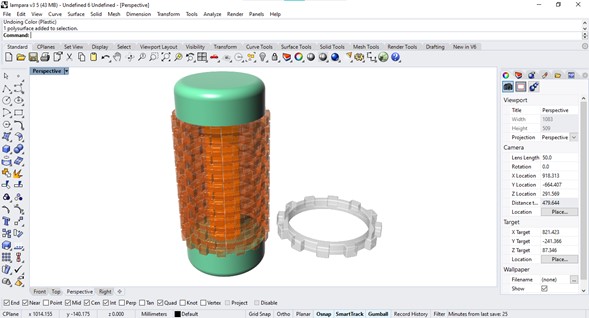
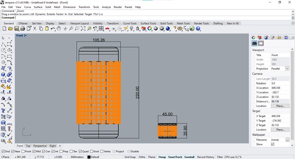
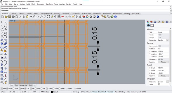
Printing my lamp in actual size at this point would be a waste of time and material so I printed instead a scaled part to evaluate the shape and mechanism. My idea was to print a prototype that had a small gap between discs so that there was just a little bit of support material between one level and another to be able to rotate the discs independently.
This printing was made on a Plaxyz printer (Marlin based DIY printer), it is not my favorite because it is a bit slow and does not have very good resolution but it was the one that was available at the time and I usually adapt to any situation. To use this you need to plug the cord, preheat the nozzle and the plate and select your file on your SD card, I generated the G code in Cura after checking that the design had the characteristics that I needed.
|
Plaxyz 3D Printer Material: PLA
|
The printing started well but unfortunately the filament was fused between the discs: the whole mechanism was canceled by melting everything into one piece and I didn't realize it until I removed the supports.
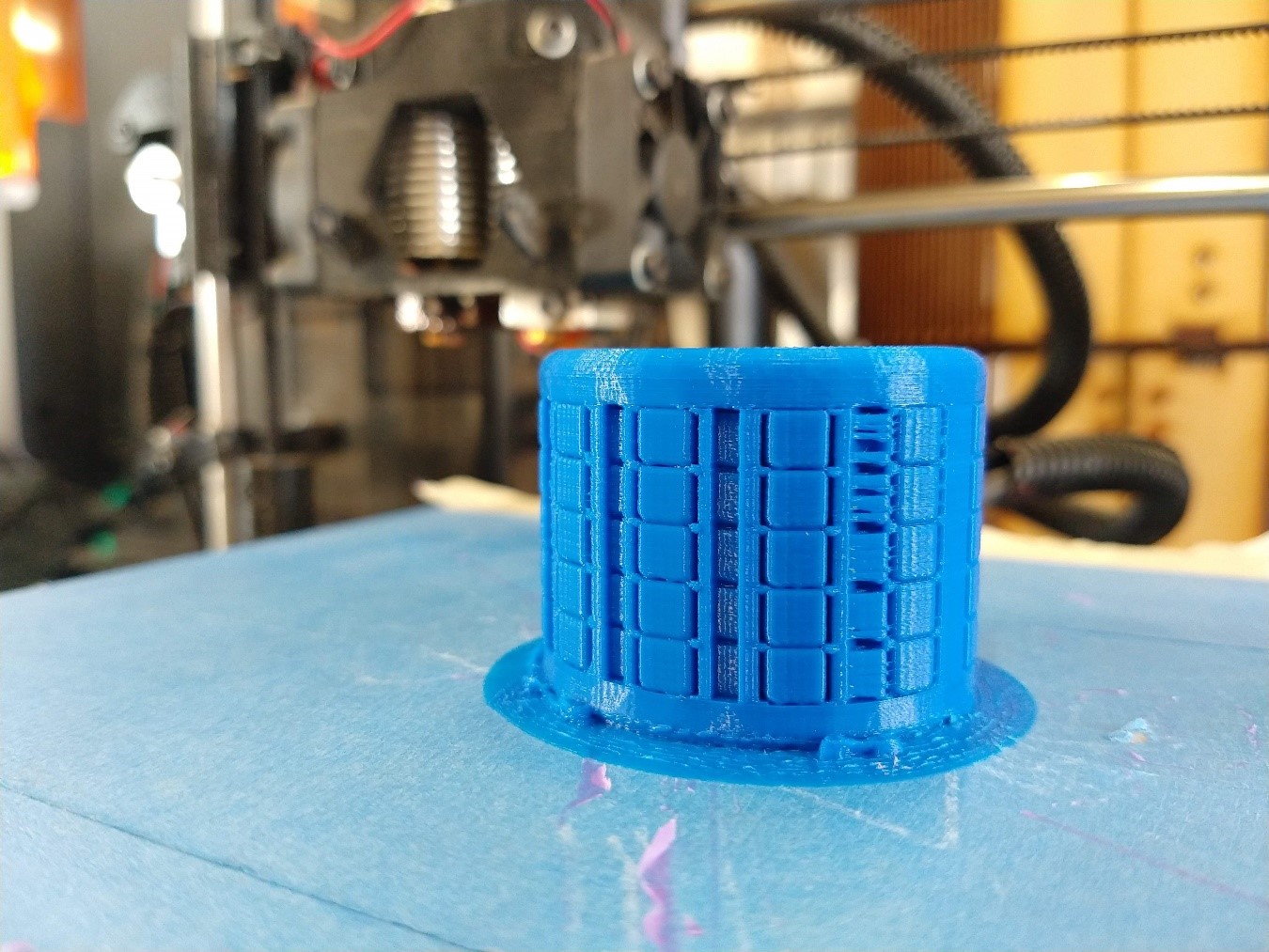
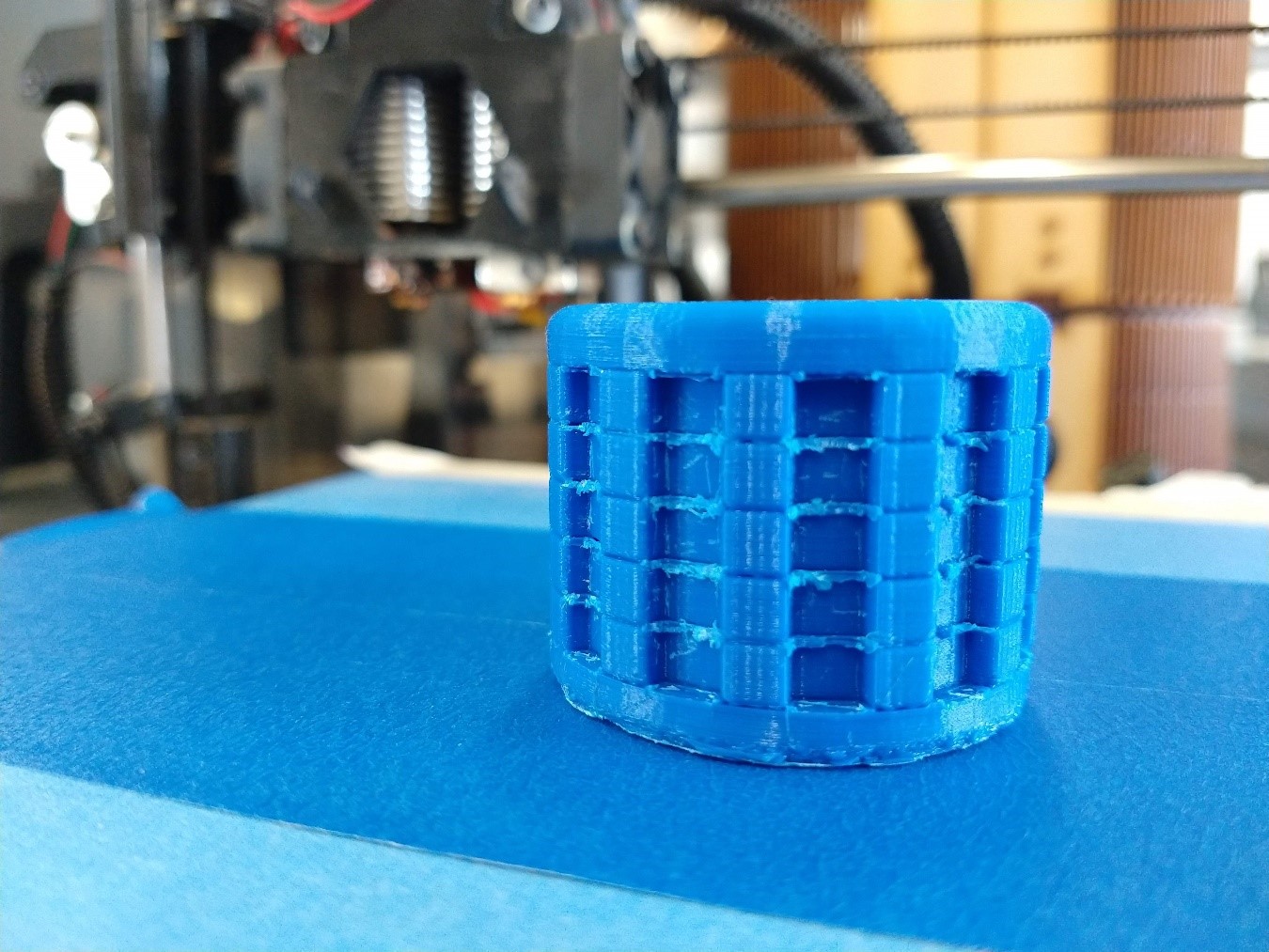
Lesson learned: heat between small parts can warp or stick them together.
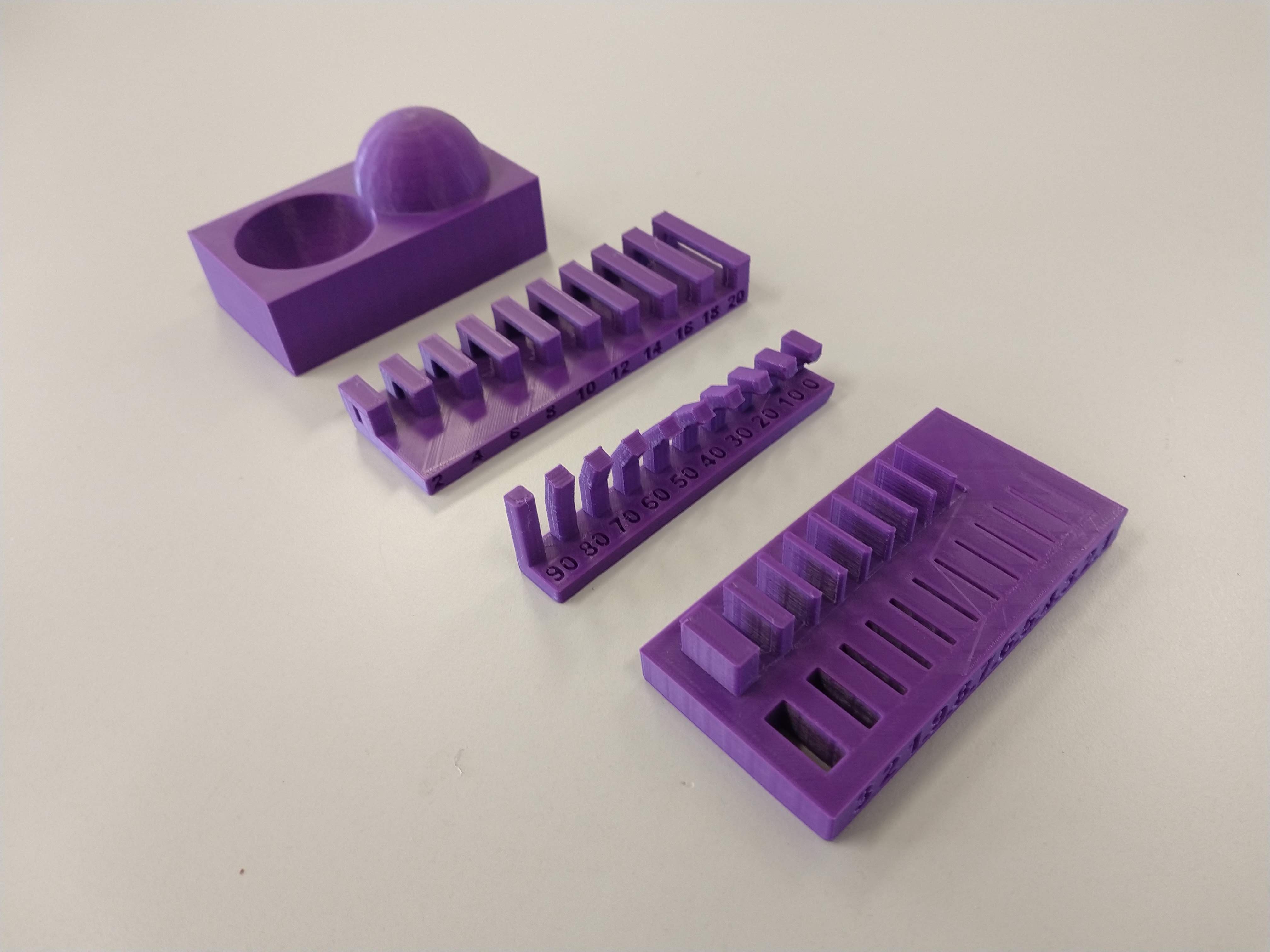
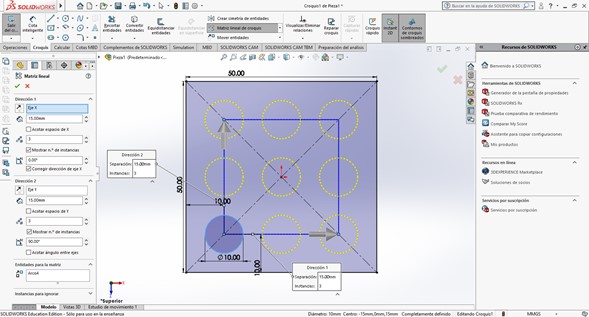
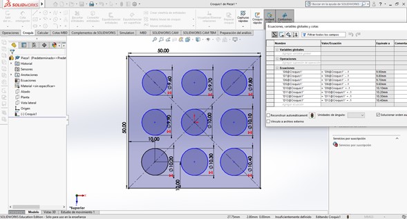
To have a reference of the tolerances that I should consider using this printer I designed in Solidworks a template with perforations of different sizes and a pin that could be placed inside, once again I benefited from the use of a parametric design software: I needed nine holes with diameters different from each other by 0.1mm and using equations I did it very quickly.
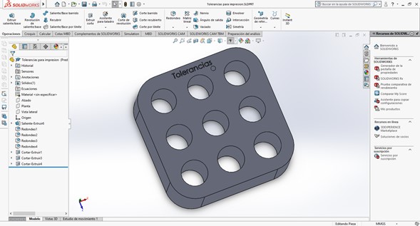
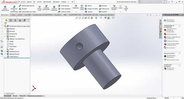
I printed and tested those pieces, the best result was 10mm on the pin and 10.4 mm on the hole, I will use this measure on my next prototypes.
3D scanning
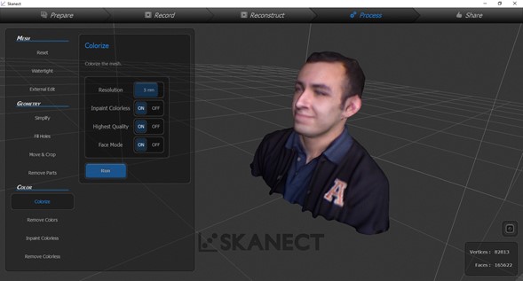
To do 3D scanning here we have a Kinect sensor, which together with Skanect software can perform scans with a good level of detail. I was not expecting any interesting results but in the end I was very satisfied with the final model, it works very well for a low cost scanning option.
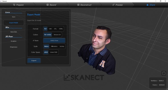
Skanect has a free non-commercial license, it features automated watertight repairs and it can export the model as .OBJ, .PLY, .STL and .VRML. The most important differences between the free version and the paid version are the resolution of the model (since the free version is limited to 5000 polygons) and the chance to export color models, but considering that not all of us have a color 3D printer the free version of the program is more than enough for most uses (I used Pro version anyway). The software interface is very simple, it is managed by tabs and the buttons indicate what specific function they perform, so after a couple of tests you have fully mastered the program. The capture tab (the most important) shows a preview of the color image as well as a representation of the modeling as the information is collected, to obtain the best results it is important to place the object to be scanned at a distance in which the diagram show it on green. You can modify the shooting options such as the maximum scan time or the delay time from the moment when you click on the Record button until it actually begins to capture information, giving you the chance to place yourself in the correct position.
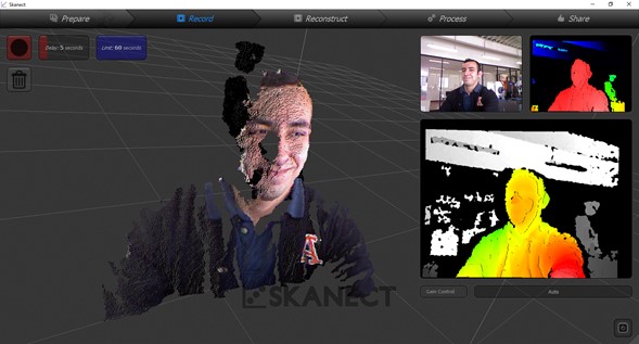
To perform the scan, it is essential to move the sensor or the subject delicately to collect information from all its angles, this must be at a reduced speed since the immediate previous scan point can easily be lost, in case this happens Just point the sensor at the subject and allow the program to first calculate the front face of the object to be scanned.
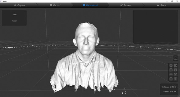
After the information has been collected you must convert your model to a watertight solid to be able to manipulate it correctly in some other program or even to print it. The program offers four levels of smoothing to have closed surfaces with a higher level of detail or smoother joints.
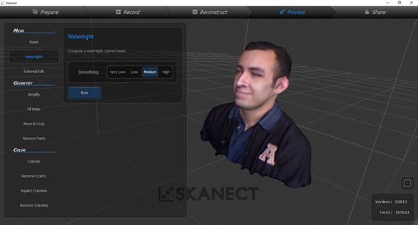
You can colorize your model using the information collected by the camera in all your photos with the Colorize button but this consumes a lot of resources and makes the file much heavier.
The last tab called Sharing has the options for saving, exporting and publishing the model.
I couldn't find any program on my PC that could visualize the colors in the model, so I chose to share it on Sketchfab instead.
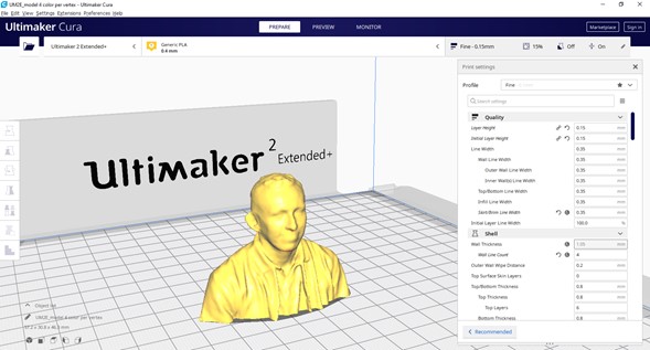
Having the model perfectly closed it was logical that the next step would be to print it, and luckily the Ultimaker was free already. I chose this considering its great detail level.
|
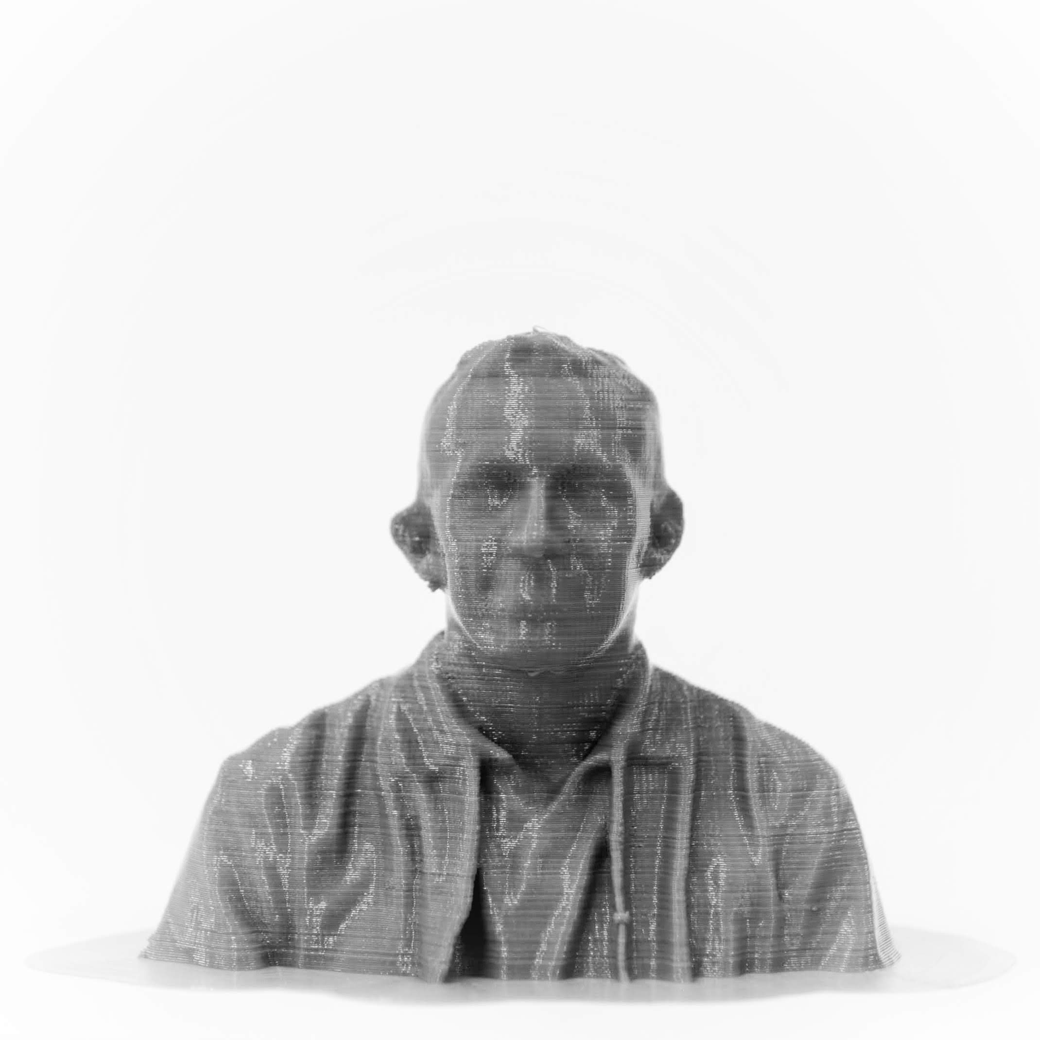
Ultimaker 2 extended 3D Printer Material: PLA
|
And the result was awesome:
Sketchfab as educational environment.
3D scanning, again
Last week we were waiting in our laboratory for our new 3D scanner to be delivered so at that time I could only do a simple scan using the Kinect, which offers acceptable results but a professional scanner has better resolution. Then I used the Faro Freestyle 2, a 3D scene scanner with a range of up to 10 meters and an error range of 0.5 millimeters, I used it to scan one of our laser cutters to make an interactive user manual.
Faro Freestyle 2
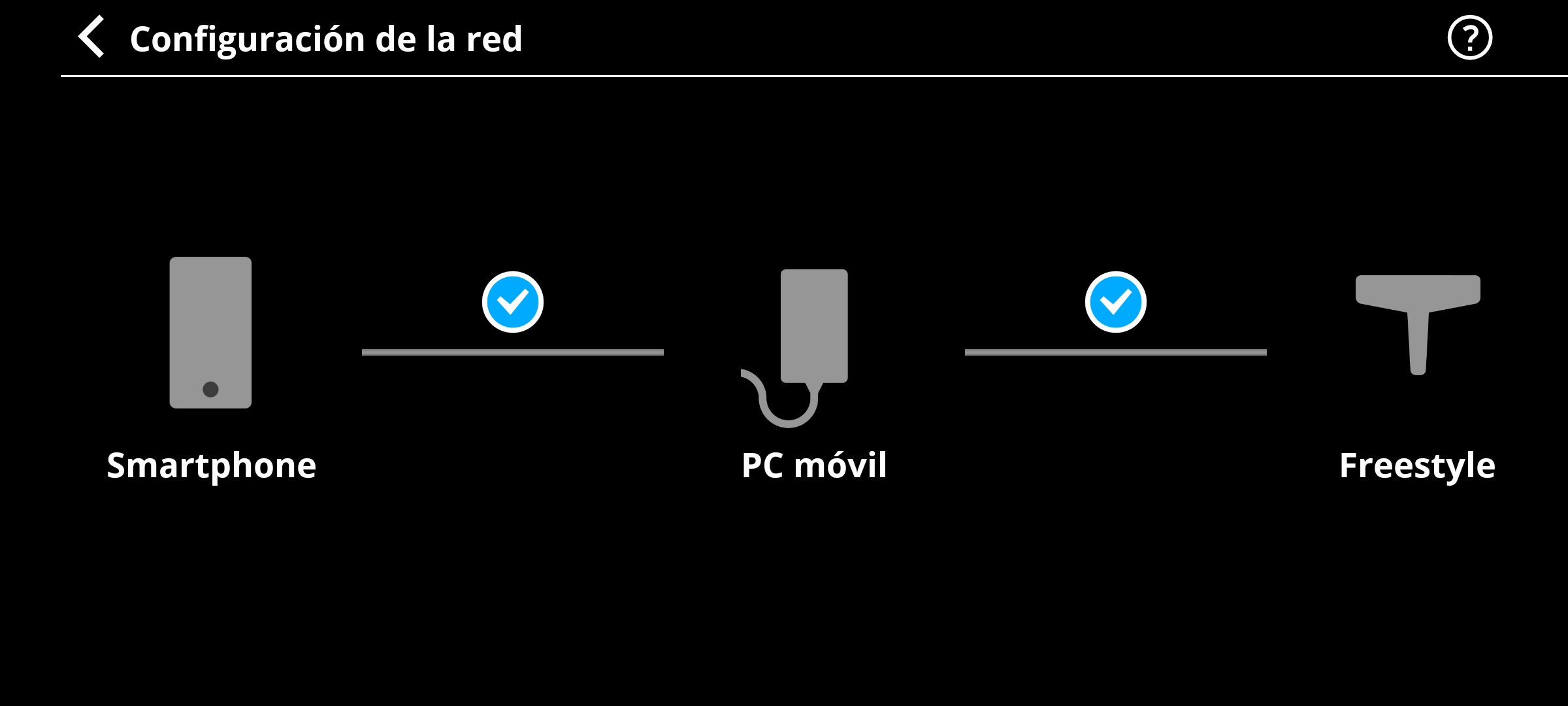
To make a scan, three pieces are necessary: the scanner (which obtains the information of the object or the scene using its optical sensors), the computer (which processes the data and exports the results) and the smartphone (which functions as an interface to monitor the scanning).
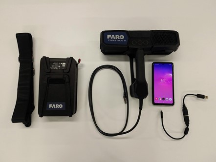
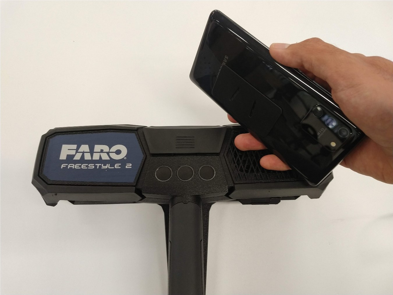
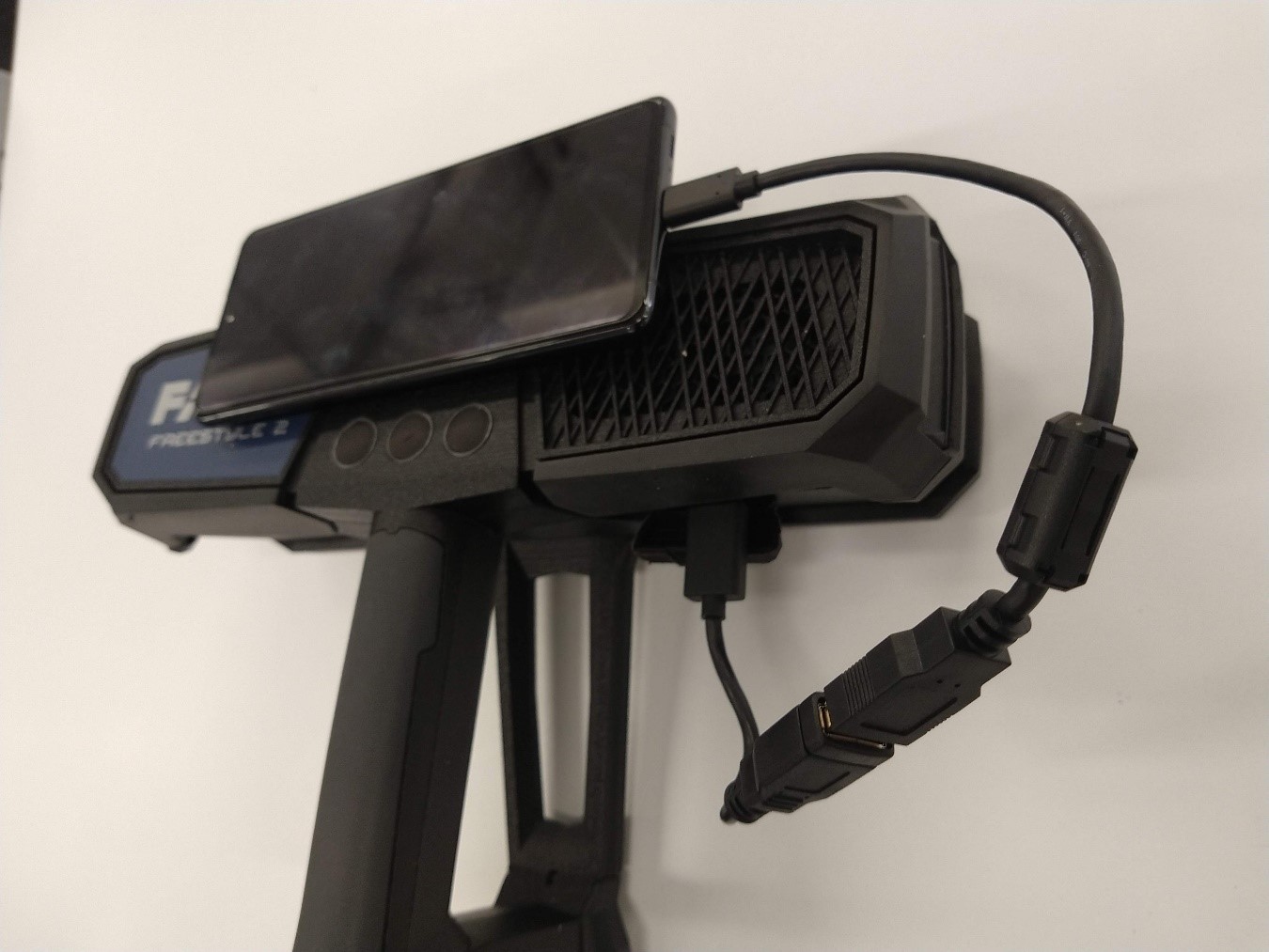
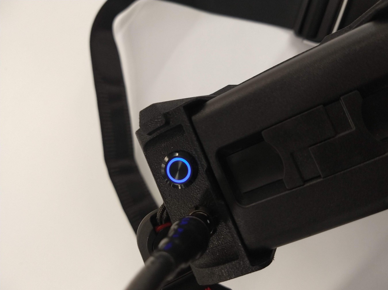
The smartphone can be connected via Wifi or by cable, in this case the smartphone is connected to the USB input of the scanner, placed on the magnetic base and the computer is turned on by pressing the button on the CPU.
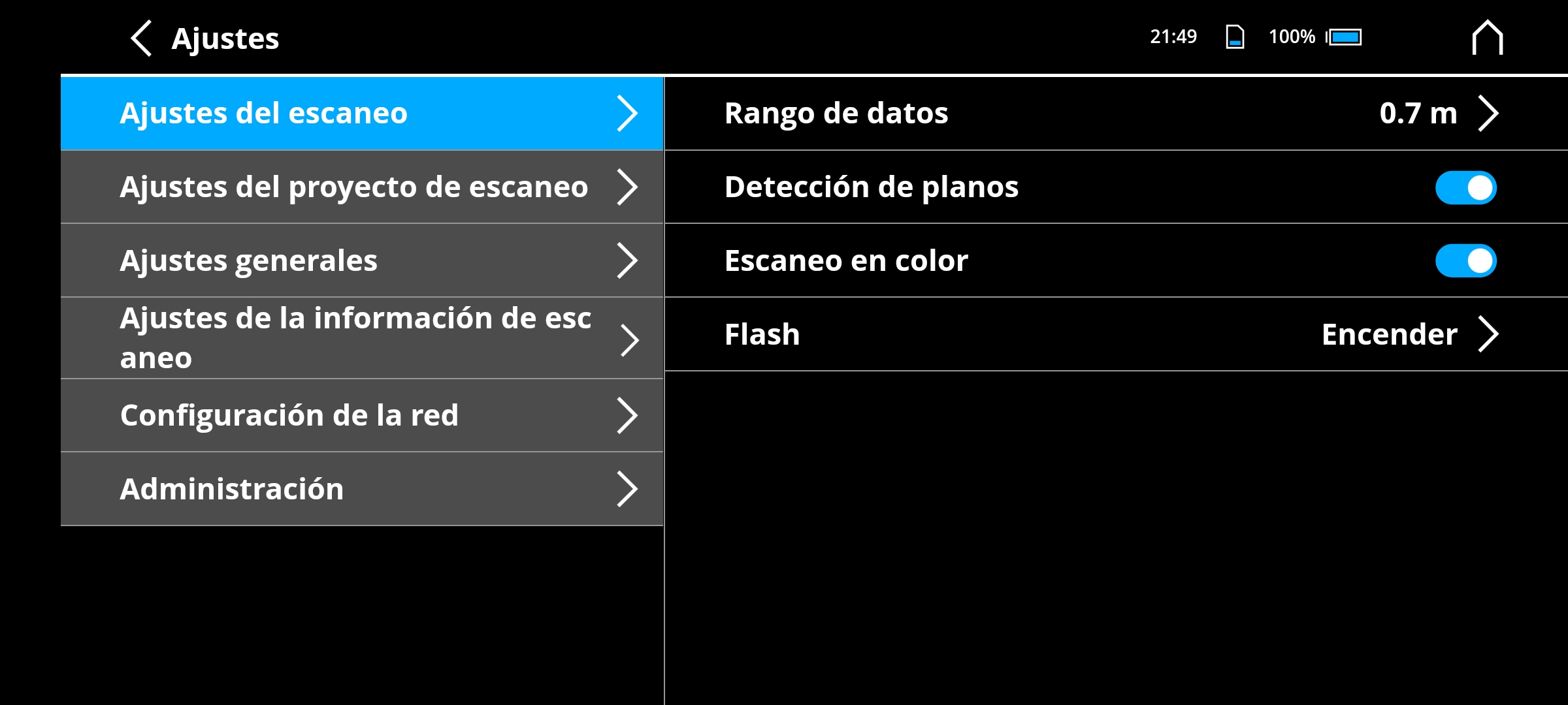
The application is free but it is only available for Android. It is very easy to use since it does not have many tools, it offers some scan settings (the most important is the distance of detection of points), it is actually a monitor of the real-time scan since the data processing is carried out in the computer.
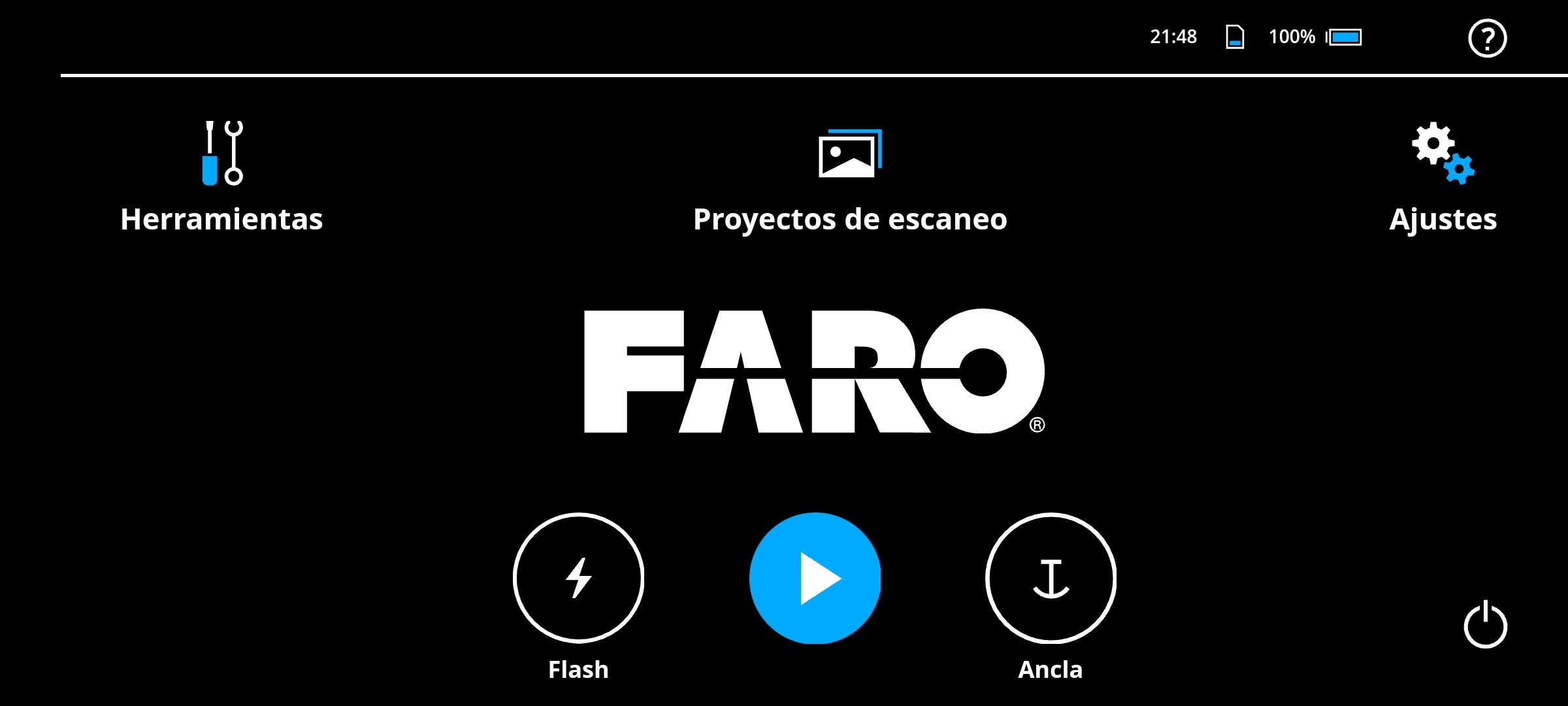
To start the scan just click on the blue button, it does not matter if it is in the application or in the scanner.
The scan must be done slowly to capture the scene in its entirety, without pauses that generate overlapping images and without sudden movements that generate a loss of continuity in the scan, it sounds very complex at first but it is all a matter of performing the movement rhythmically as if you were brushing someone's hair.
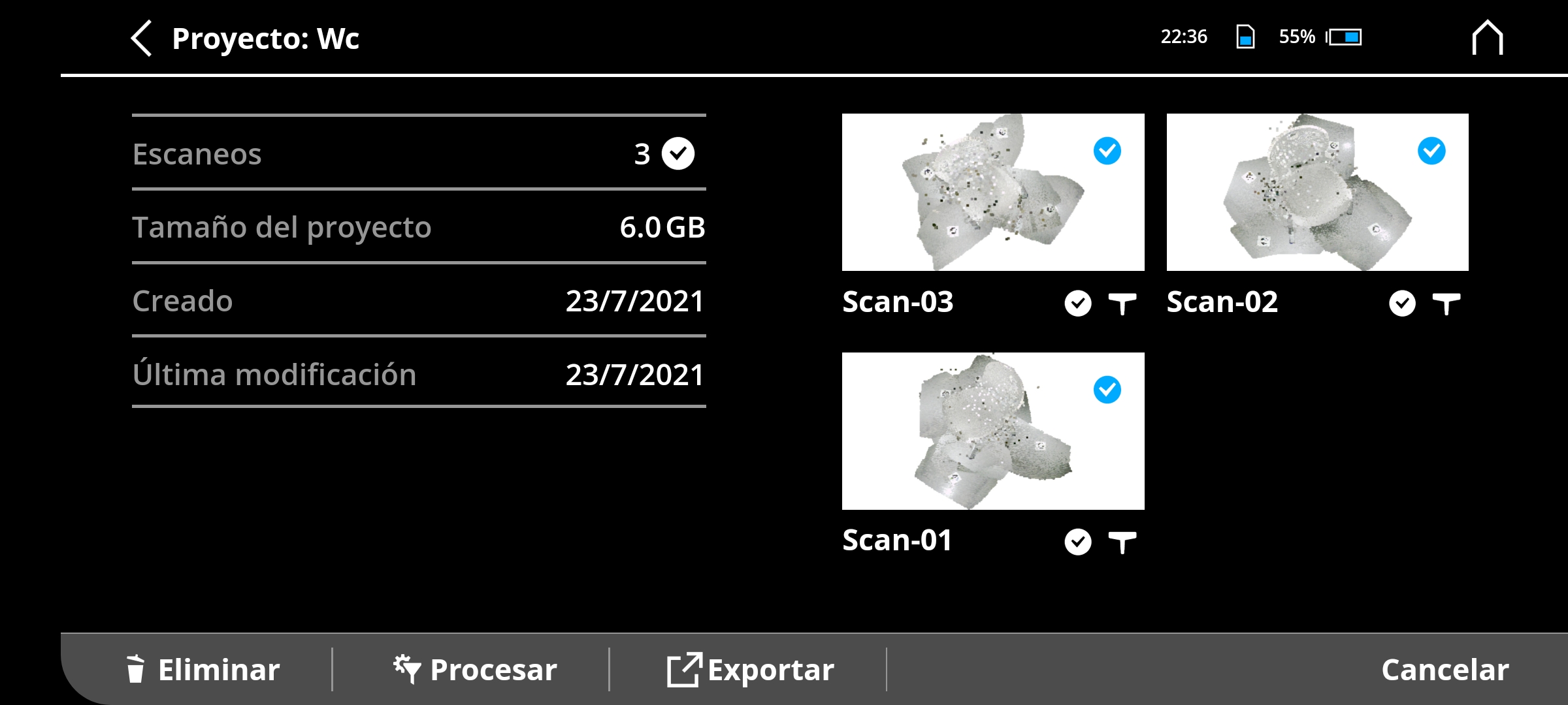
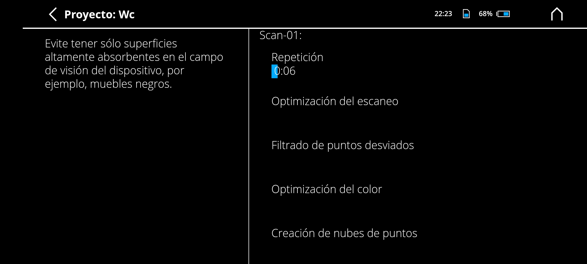
At the end of the scan, the data must be processed to generate a point cloud that can later be edited in 3D modeling programs. The scanner can generate two types of files: E57 and XYZ, I prefer to work with E57 because it stores color information, the files weigh less and modifying them consumes less resources.
Creating meshes on Scene
Creating meshes from point clouds can be a headache (and a huge waste of time between each trial and error) so I used Scene, the official scanner software to process the scan projects, it makes it very easy to conversion from point cloud to meshes.
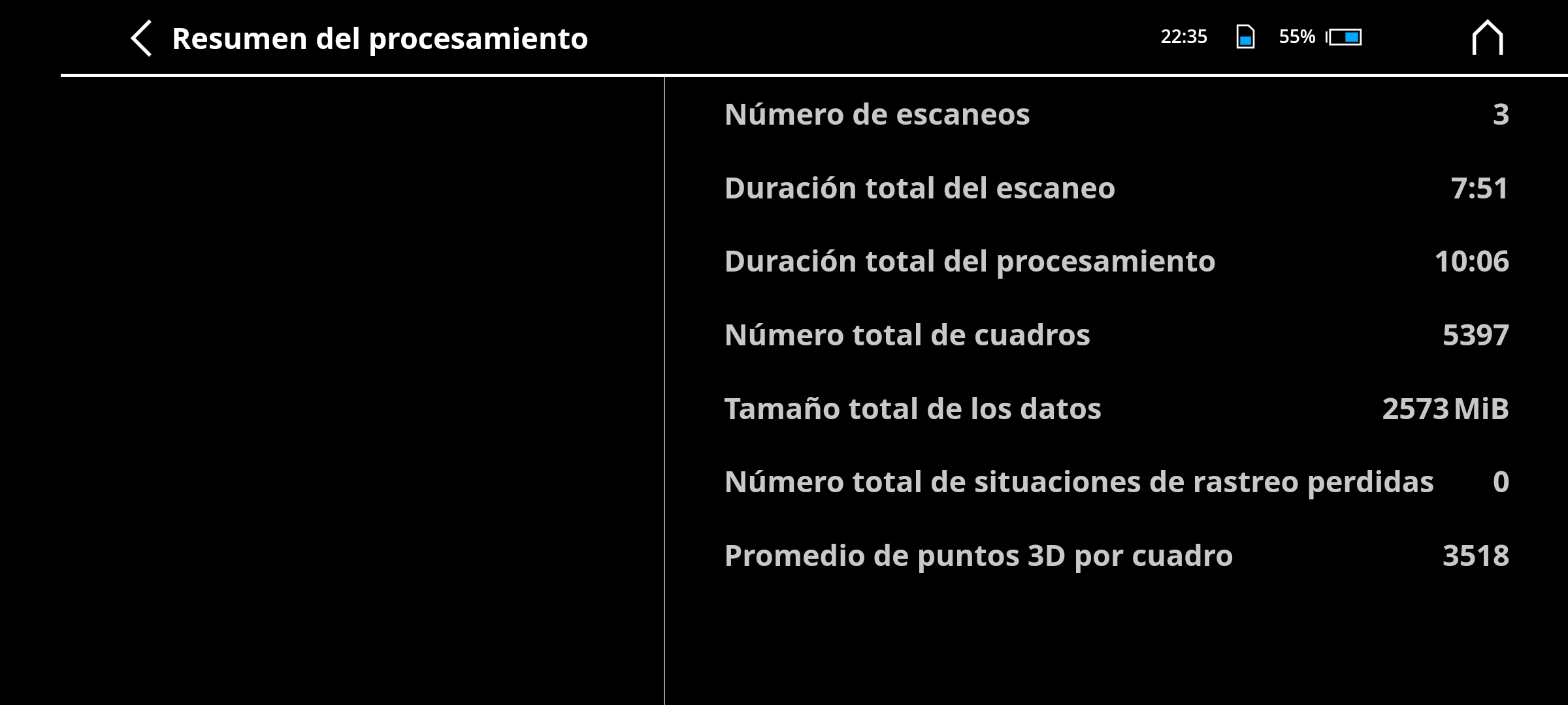
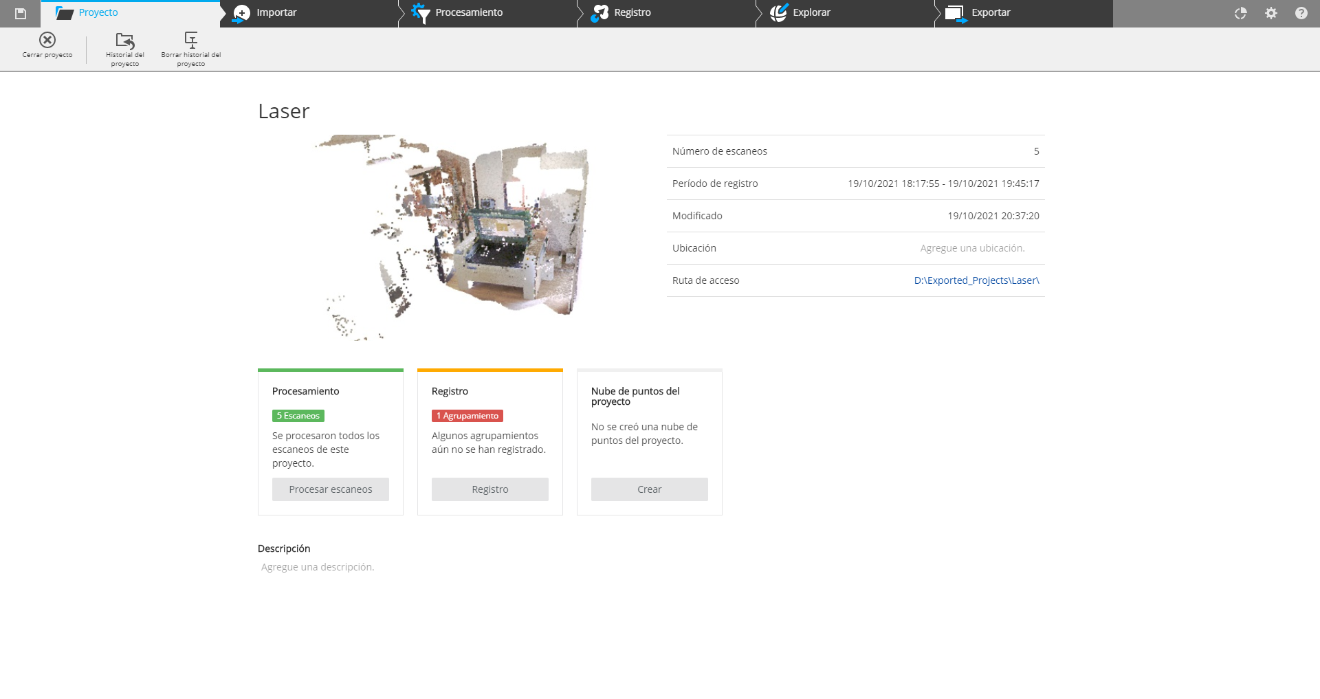
The project window provides a summary of the information contained, such as scan logs or point clouds after they have been created.
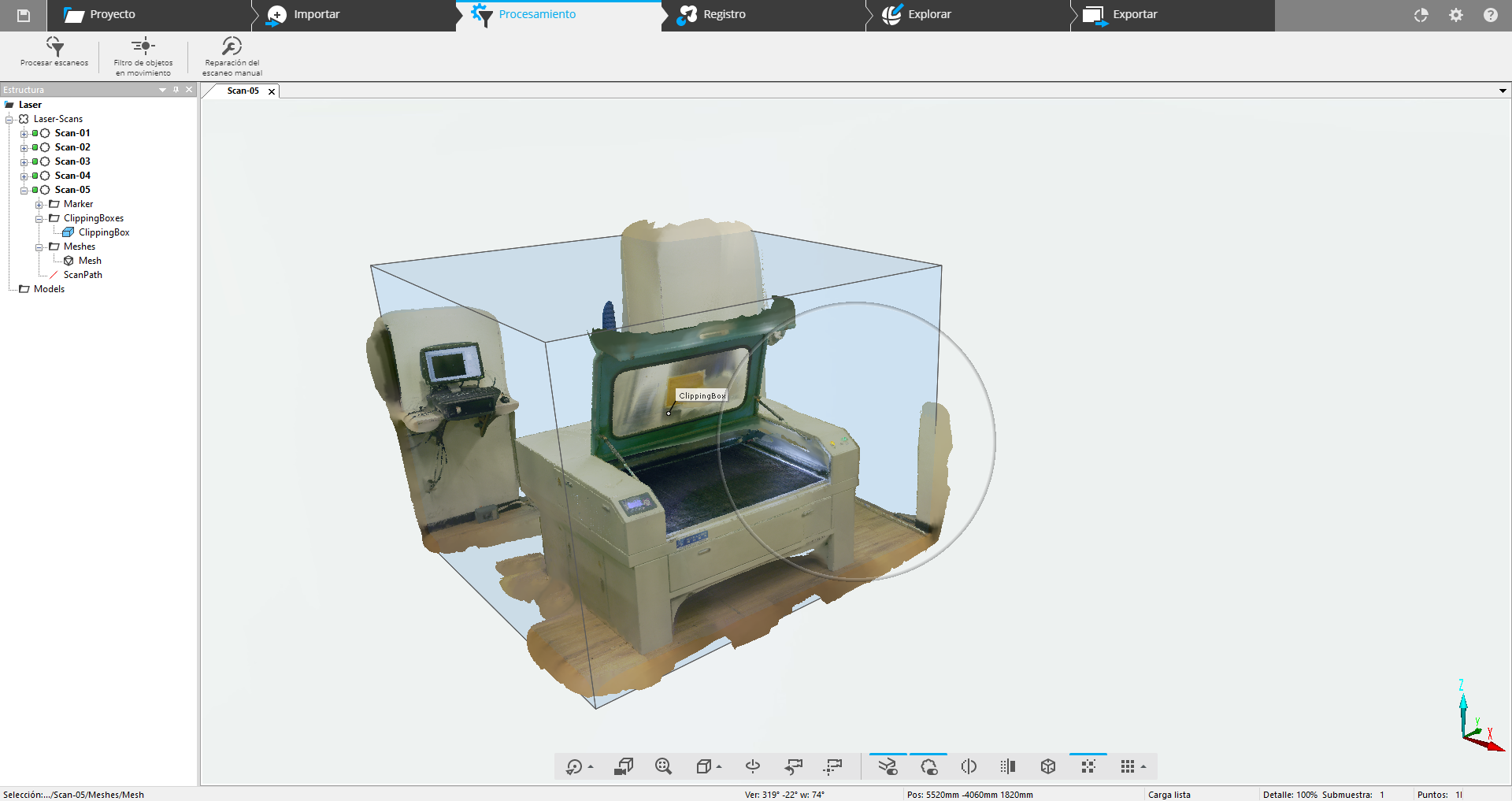
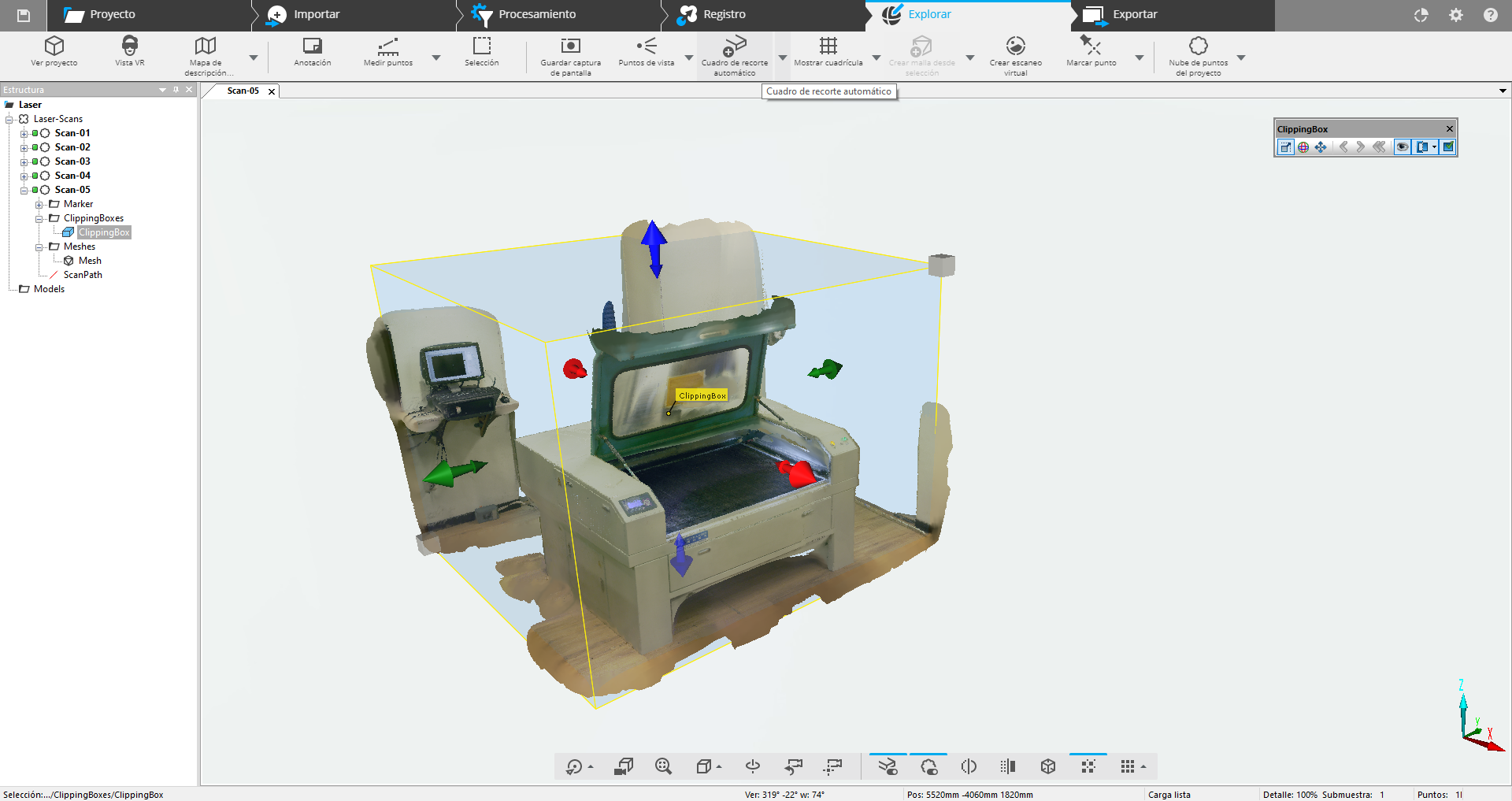
The first step to edit the project is the creation of a Clipping box, a box that contains the relevant information of the scan, this can be used to delete points by sections without having to select one by one. You can delete what is inside or what is outside of the box with the corresponding button in the lower toolbar.
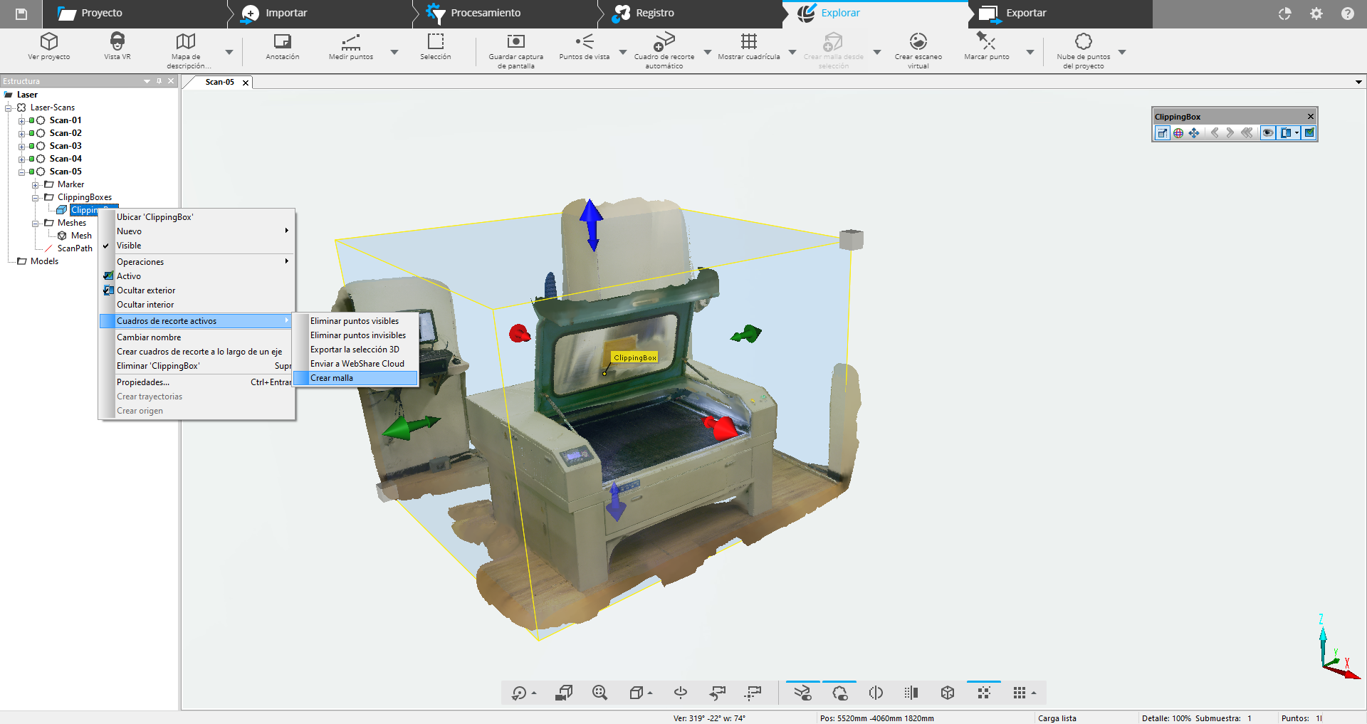
After deleting the unnecessary sections, a mesh can be created from the contents of the Clipping box by simply selecting the corresponding option when clicking the right mouse button.
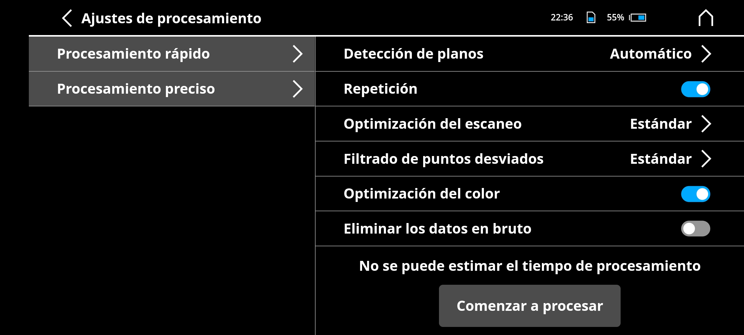
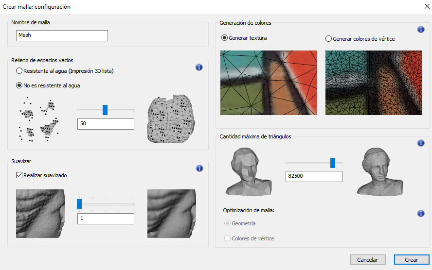
The software asks for parameters of resolution, texture and impermeability.
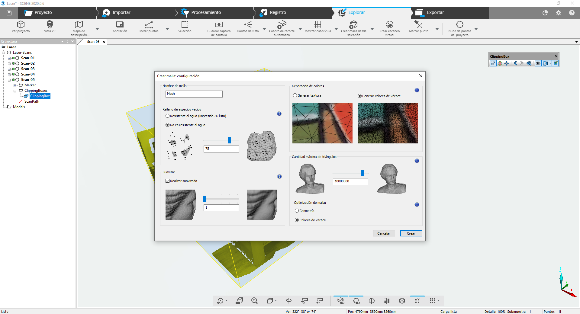
In this test the parameters that worked best for me were these:
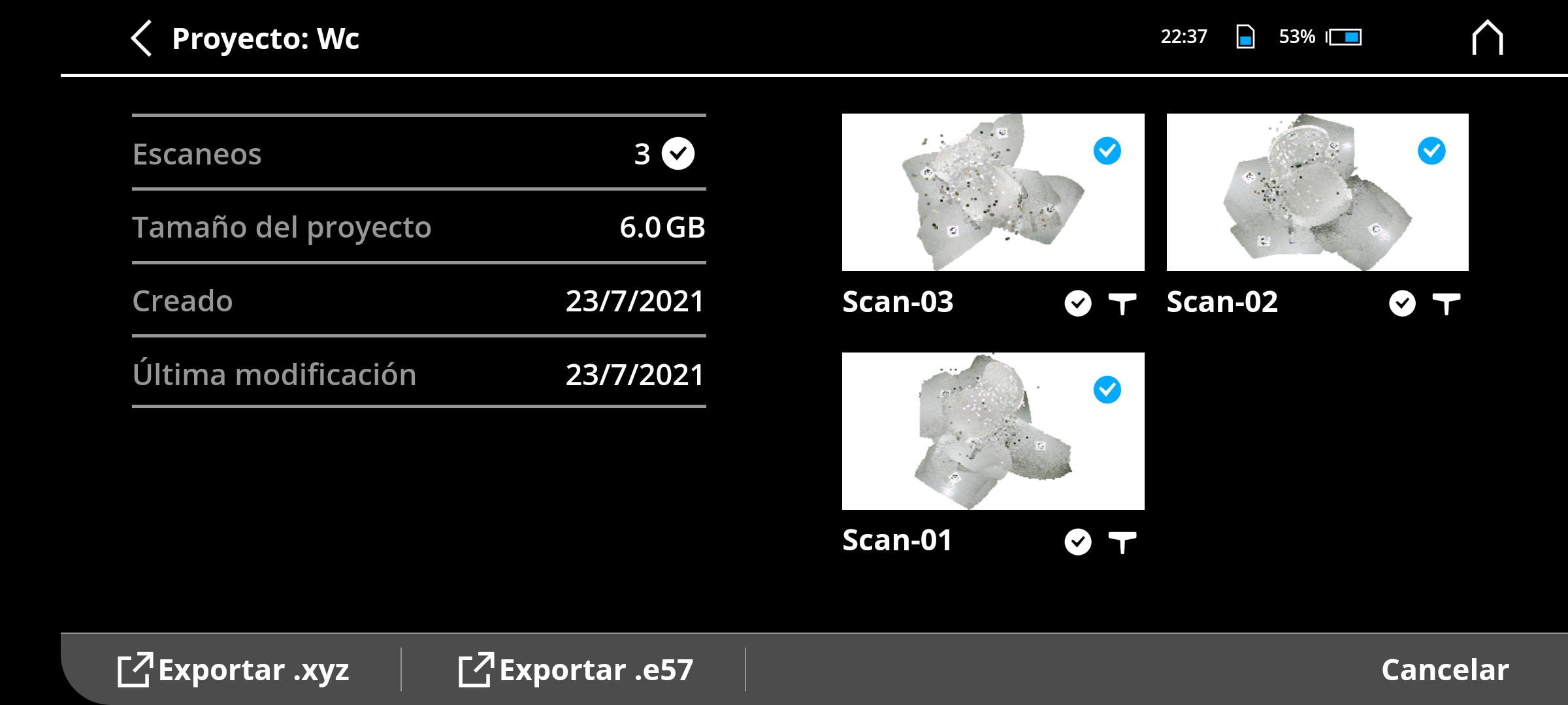
After generating the mesh, simply click on Export to generate an STL or OBJ file (the latter preserves the textures generated in the previous step).
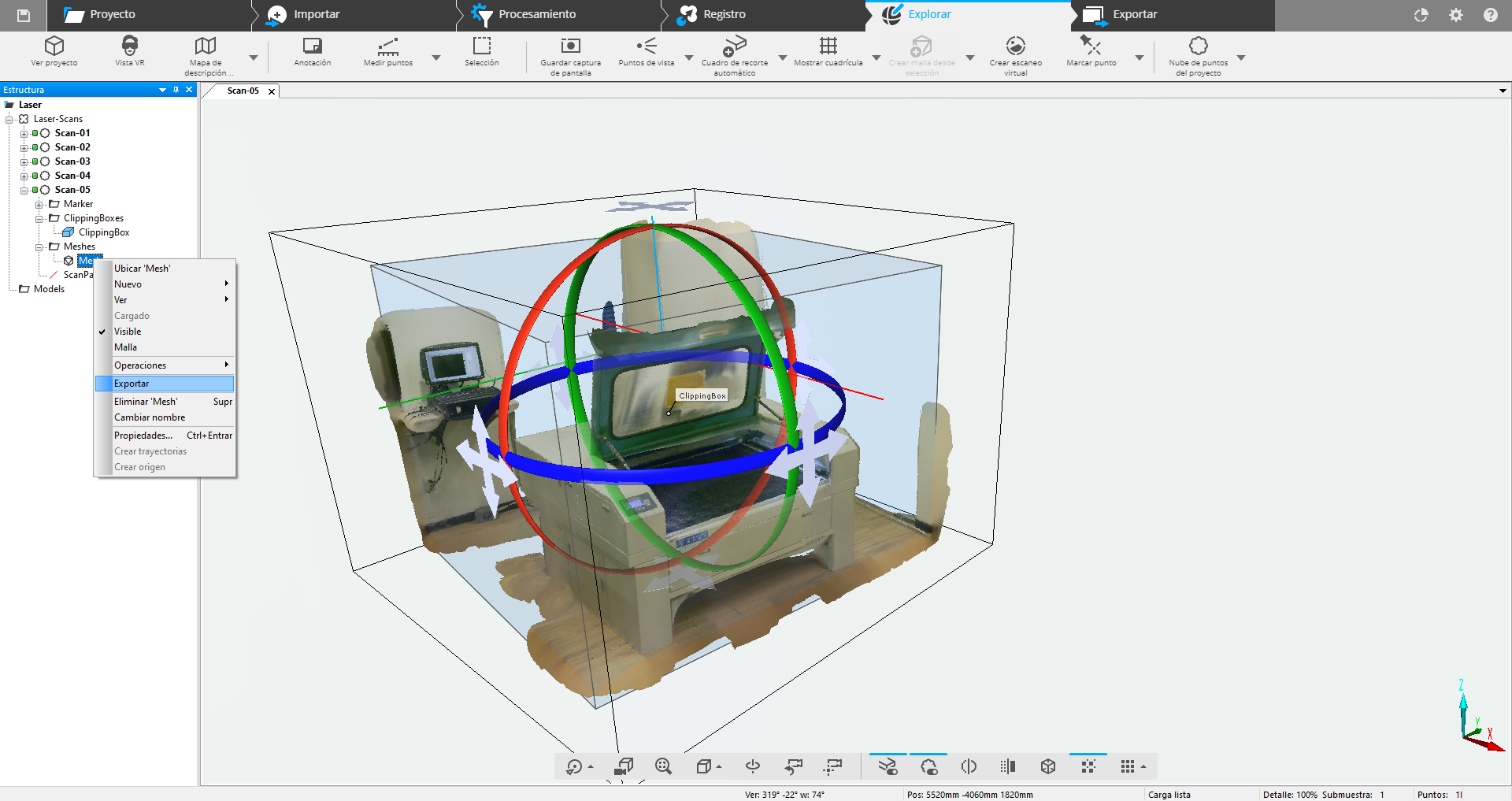
Sketchfab allows you to upload models with textures and share them on the web, in this case I uploaded the OBJ file that I generated and added the instructions for using the laser cutter as an interactive tutorial.
Files
You can download the 3D model of my scan here.
You can download the 3D model of my lamp here: .3DM and .STL.
Tuesday, May 25.
Going back to the goal of this assignment (which is to do something that can't be done subtractively), I did a new tolerance test, I modified my model adding more space between every disc and printed it using the Ultimaker because it's more reliable, and the results were better: now the disks can rotate freely and the whole model was printed in a single piece that integrates the discs, the central pivot and the upper and lower covers. You can download it there.
For the final prototype of my project I was thinking of printing all the lamp structure taking advantage of this principle but it would take too many time, so instead I decided to cut it on acrylic.
Thursday, June 10.
I made a new model for my lamp and today I printed the base.
|
For this assignment I:
|