How to make (almost) anything.
Week 03. Computer-Controlled Cutting
Work done in the Lab under the guidance of my remote Instructor to accomplish the weekly assignments.
This week I made a parametric construction kit, a press fit template to measure kerf and some vinyl decals.
My weekly schedule:
| Wednesday, February 10 | Thursday, February 11 | Friday, February 12 | Saturday, February 13 | Sunday, February 14 | Monday, February 15 | Tuesday, February 16 |
| Global class | Solidworks testing | Construction kit design and cut |
Solidworks equations testing Vinyl sticker design |
- |
Recitation Viny sticker cut Press-fit template design and cut |
Upload documentation |
Group assignment
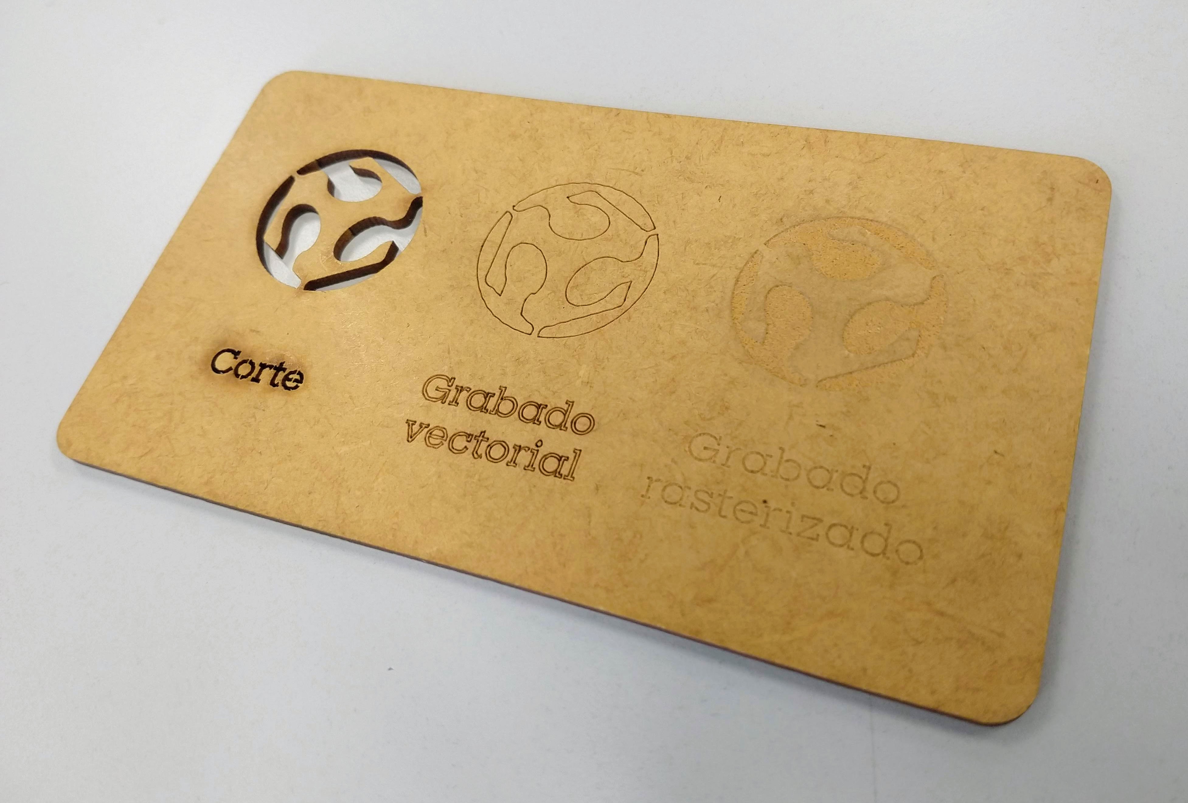
For this Group assignment we characterized our lasercutter's parameters. You can read it there.
I made the characterization of speed and power values for cutting 3mm MDF.
I've been working on Solidworks so I made my press fit template there using equations instead of fixed dimensions.
First I drew a rectangle with seven small rectangles inside, specifying only the global dimensions.
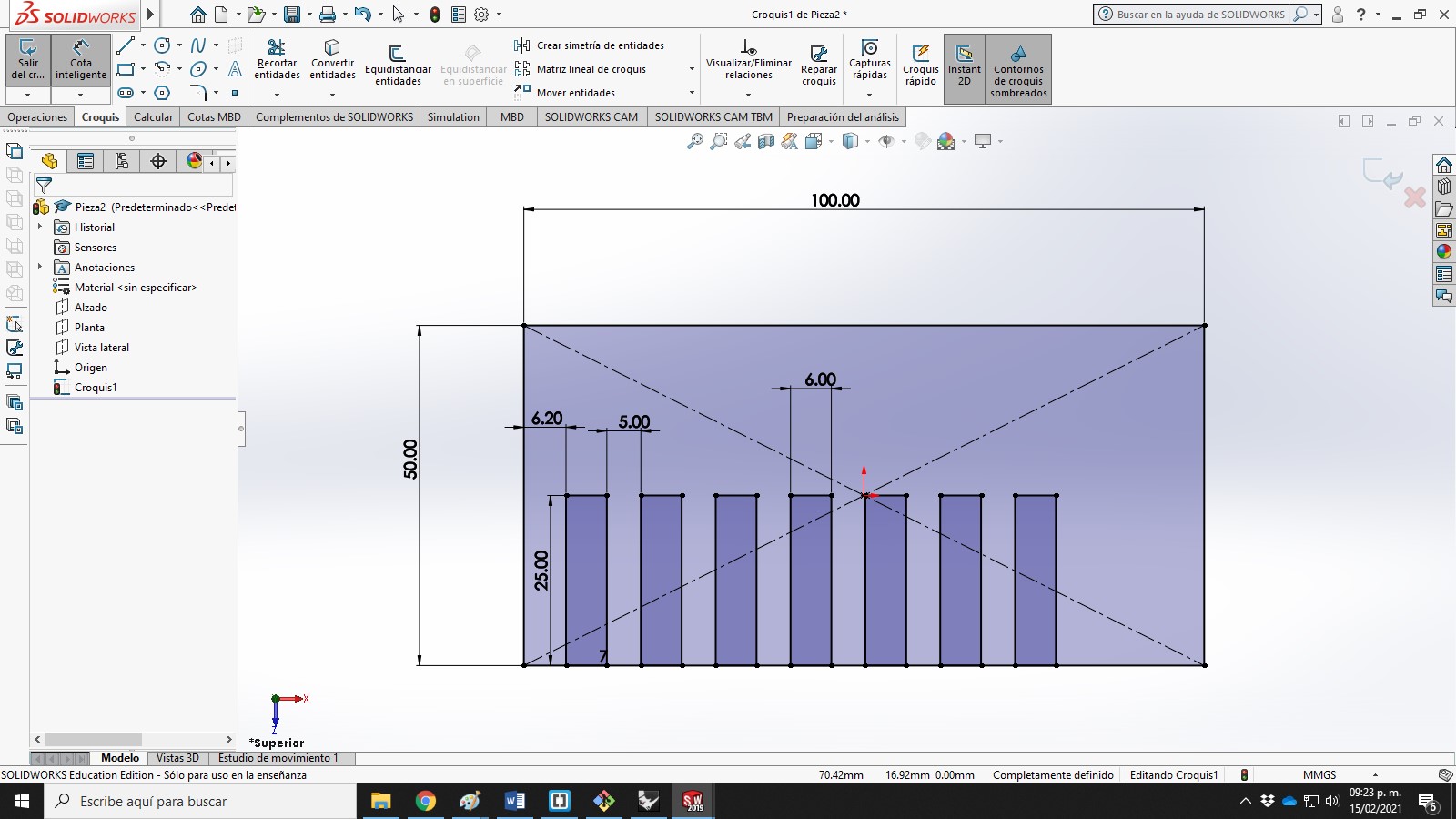
I wanted each slot to have a 0.1mm difference from the next one so I only set the numeric dimension of the central slot, on the following ones I set a formula like this: ="Previous Dimension Name"+0.1mm.
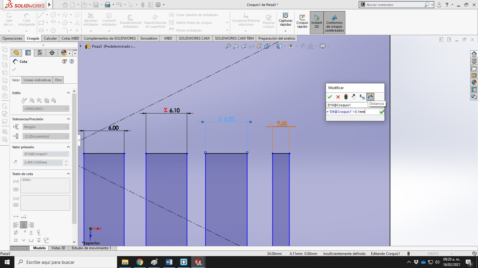
The slots on the left were made with the inverse formula: ="Next Dimension Name"-0.1mm.
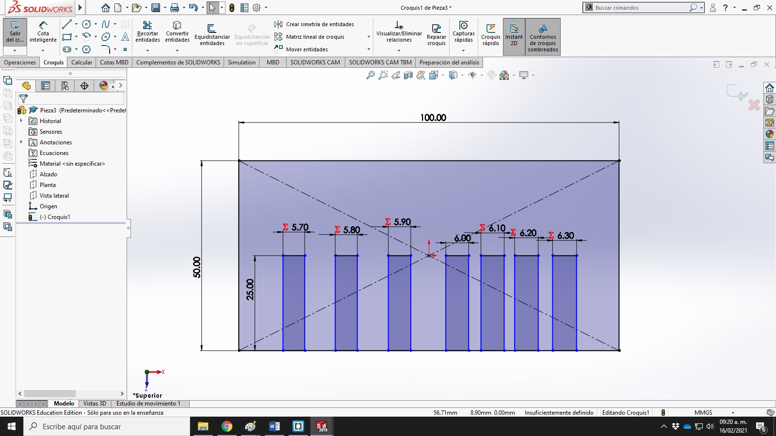
To get a clean design I needed all the slots to be equidistant from each other, so I made a formula subtracting the thickness of all the slots from the total width of the piece and dividing that number by 8, which is the number of spaces with that measurement.
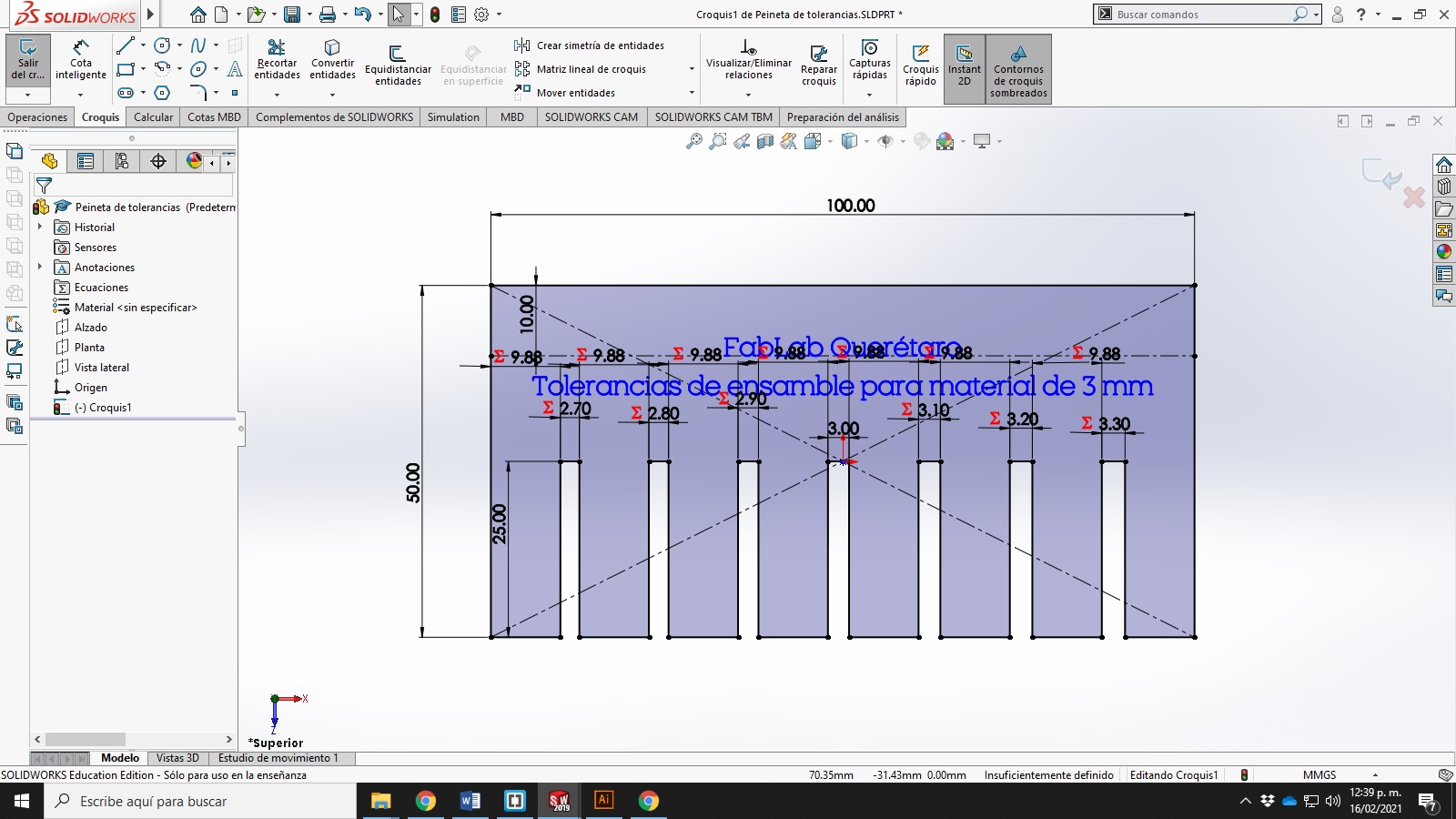
Then I only needed to enter the thickness of the material and all the formulas updated the values.
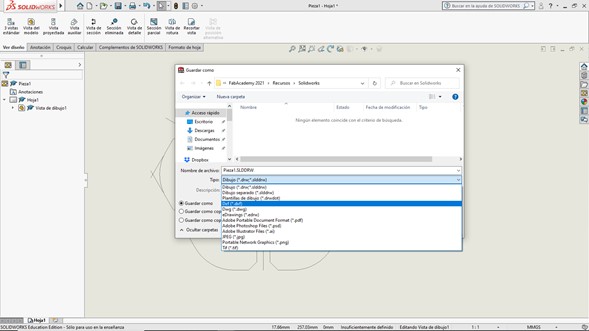
I made a drawing and saved it as .DXF file.
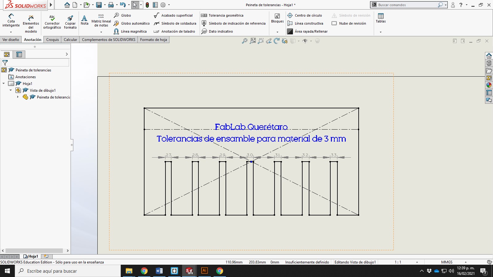
And finally I cut it (maybe for this assignment I should have made first this file and then the construction kit).
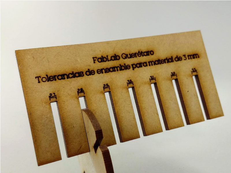
This file will help to understand the kerf width on any kind of material. This was my contribution to the group assignment.
Parametric design
To make the parametric construction kit I thought that I should start with simple pieces considering that I am just starting practice with Solidworks, so I made two basic pieces that I could edit in their general dimensions as well as in the thickness of their union to be able to use them in different materials.
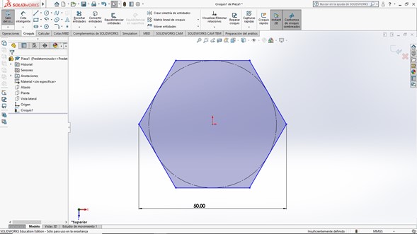
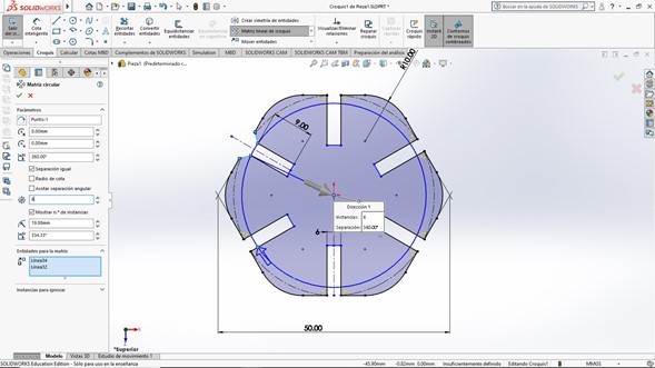
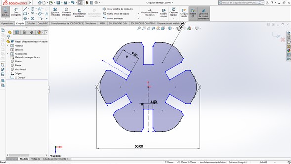
I started by drawing a hexagon.
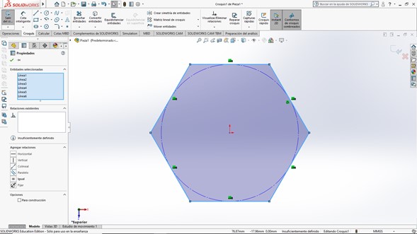
I assigned it a measure using a "smart dimension".
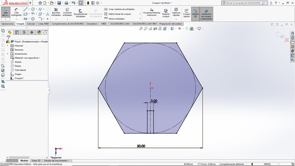
And I drew a rectangle that will later be the joint.
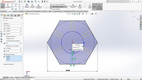
I made a polar array to replicate the rectangle on all six sides of the hexagon.
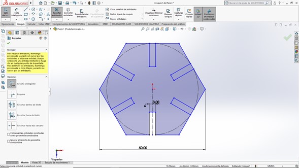
And I cut out the inner parts of the rectangles to get the joints.
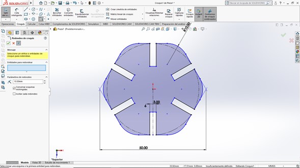
I rounded the corners to give it a more attractive shape and not hurt my fingers during assembly.
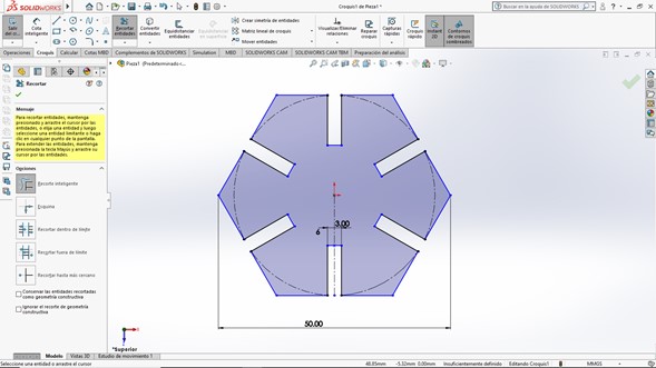
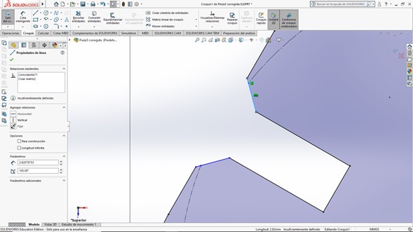
Neil showed us different joint models, for this exercise I thought the best would be press-fit with chanfer, for the chanfer I drew a line at 105 °, reflected it and made another polar array so that all the joints had this detail. After trimming the excess lines my sketch was ready.
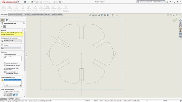
To send the file to our laser cutter it is necessary to generate a .DXF file, which can be done quickly with the Drawing option, selecting the top view of the piece and select the .DXF extension when saving. I don´t understand why Neil doesn´t like .DXF files, these works pretty good between different programs without any scale or units issues, and even if I wanted to use another filetype our laser cutter would only work with .DXF and some .AI files.
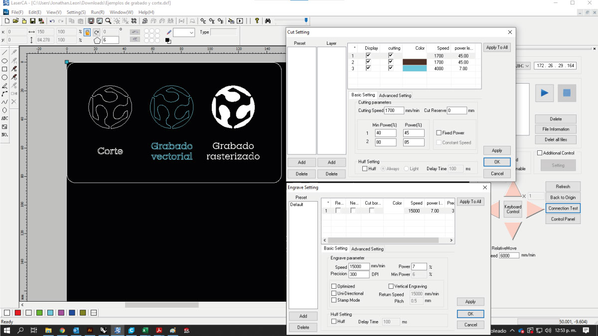
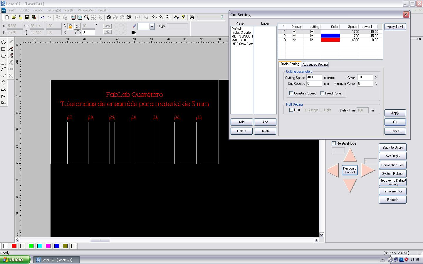
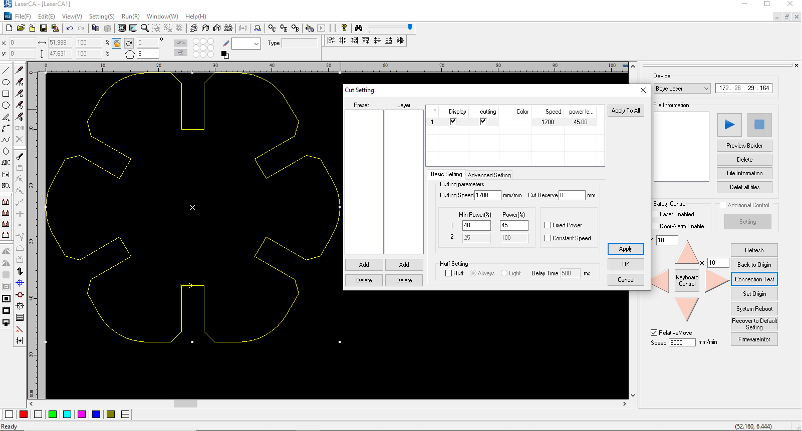
Our laser cutter uses LaserCA software which has some basic drawing tools to be able to repeat, mirror or remove parts.
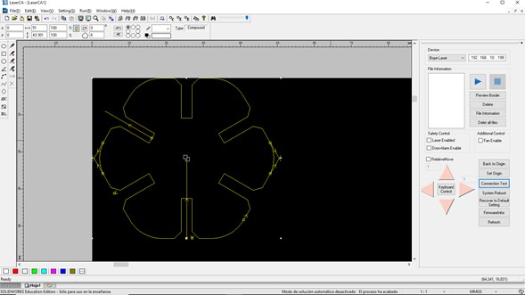
On this 100w machine we use 45% power to cut 3mm MDF at a speed of 1700 mm/min.
It is very important to calibrate the distance from the lens to the surface of the material, we do this with an acrylic tool that has the exact measurement. If this step is omitted, the beam thickens and loses power so that it cannot completely cut the material.
|
Boye 100w CO2 Laser cutter 3mm MDF or Plywood
|
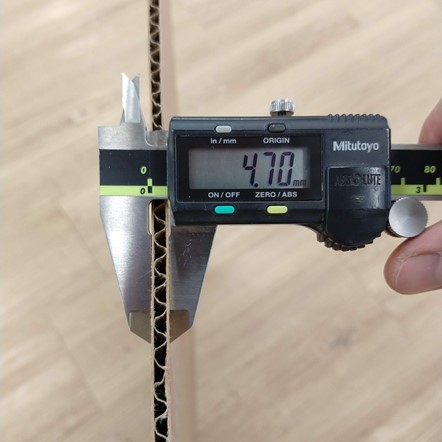
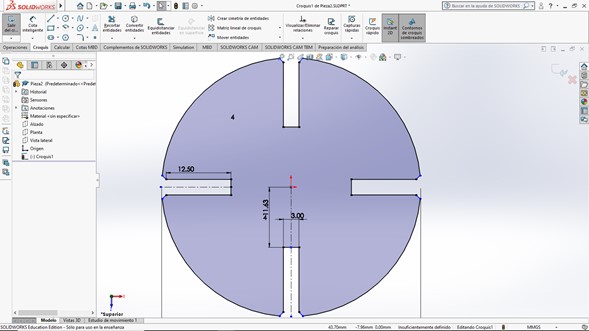
After cutting a test piece I remembered Neil's comment about the advantages of using corrugated cardboard in laser cutting, so I swapped the 3mm MDF for 4.70mm corrugated cardboard. This would have been a problem if my design wasn't parametric, luckily I only had to change one number and the unions for the whole design were updated.
A quick change on my Solidworks drawing file.
After editing the thickness of my joint I designed another similar piece, now with a circular shape..
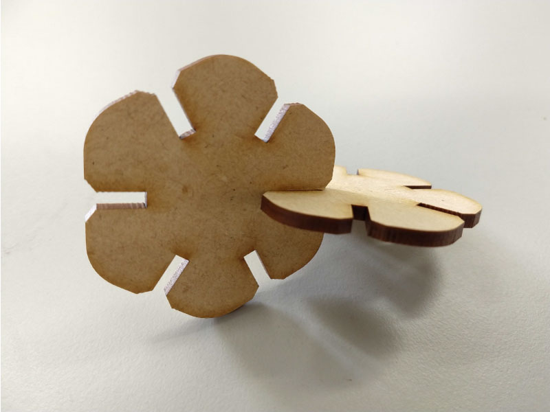
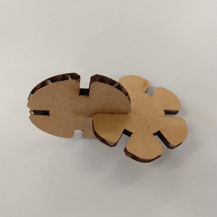
I cut a piece from each to verify that they had a nice joint. As I was satisfied with the result I cut a few more pieces.
|
Boye 100w CO2 Laser cutter 4.7mm cardboard
|
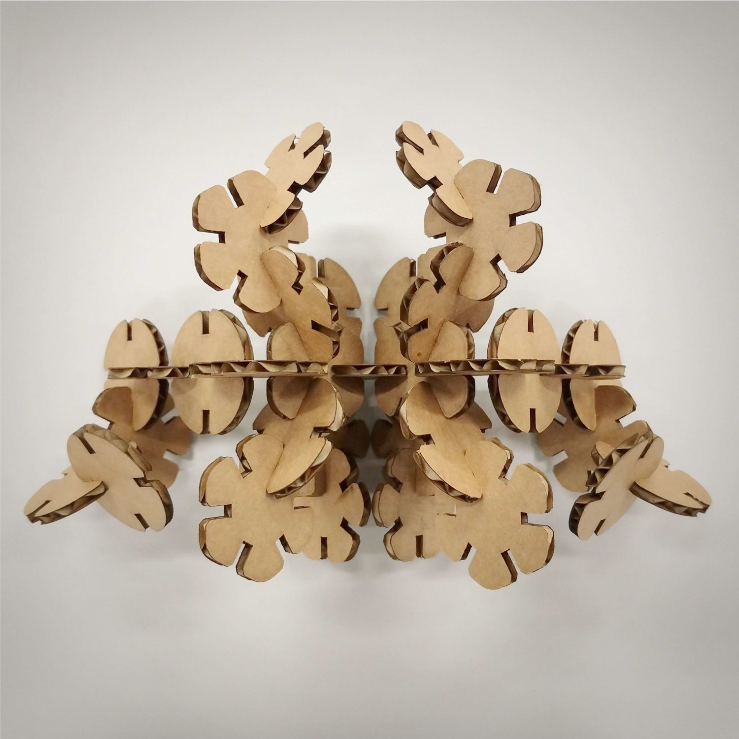
I upcycled a cardboard box that would go to the trash so I got a lot of pieces that built a symmetrical set which I really liked.
Vinyl cutting
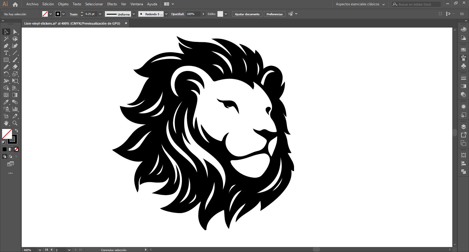
I love to make stickers, I put them everywhere. For this assignment I first tried to make a logo illustrating something from my final project to make progress on that, but I didn't like the result and it definitely wouldn't work on a vinyl sticker so I preferred to make a generic dual layer sticker for my laptop.
I started vectorizing an image on Illustrator, a lion because it´s my last name.
I made an offset on the external stroke to get some space on the backing vinyl.
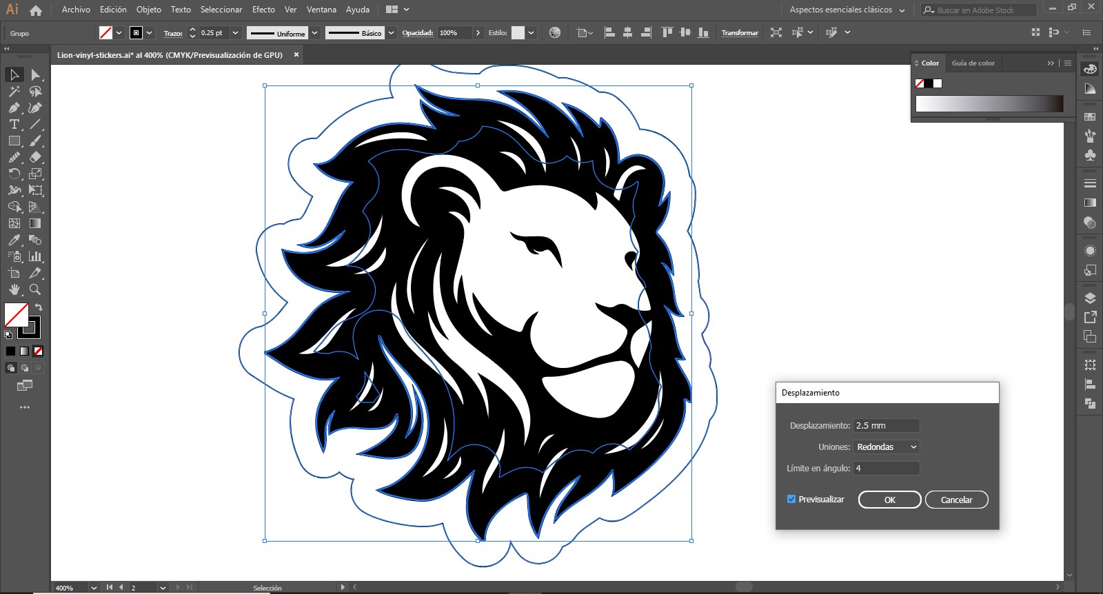
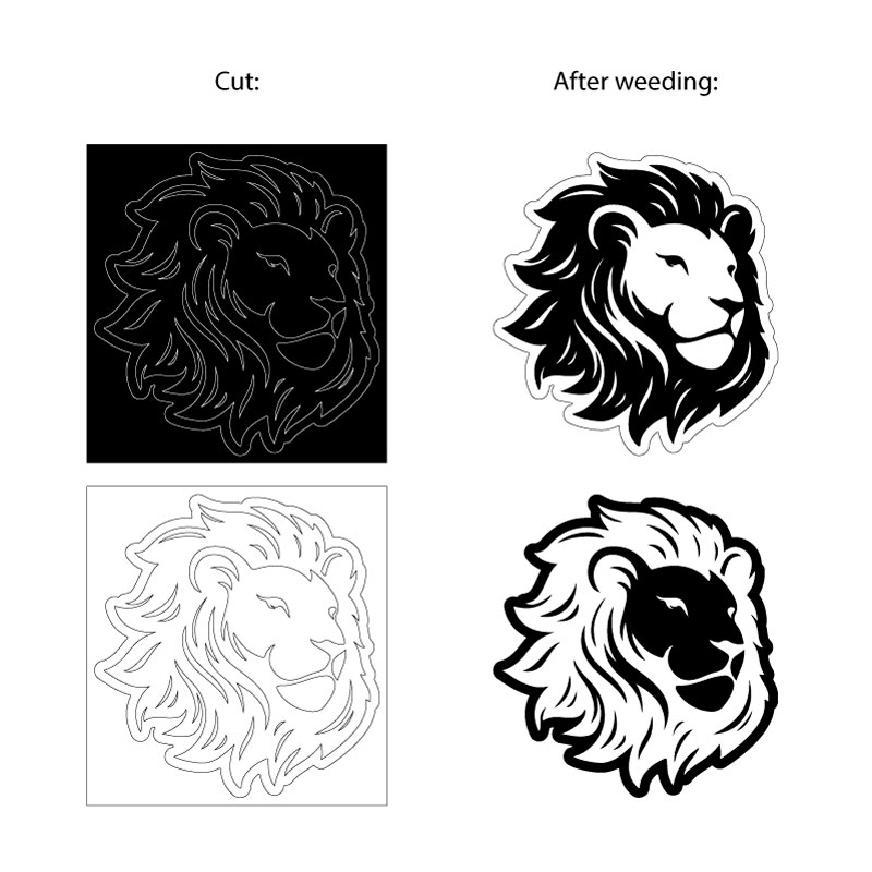
To be able to get two different stickers I just made a copy so I could weed different pieces on each, like a negative image. On stickers with more than one layer I usually make a surrounding square to get a visual reference to place the second layer above the first one, it´s like using registration marks to get the correct position on every piece.
We use GreatCut with our GCC vinyl cutter, it works directly on .AI files so I just had to save my work on Illustrator and import it there.
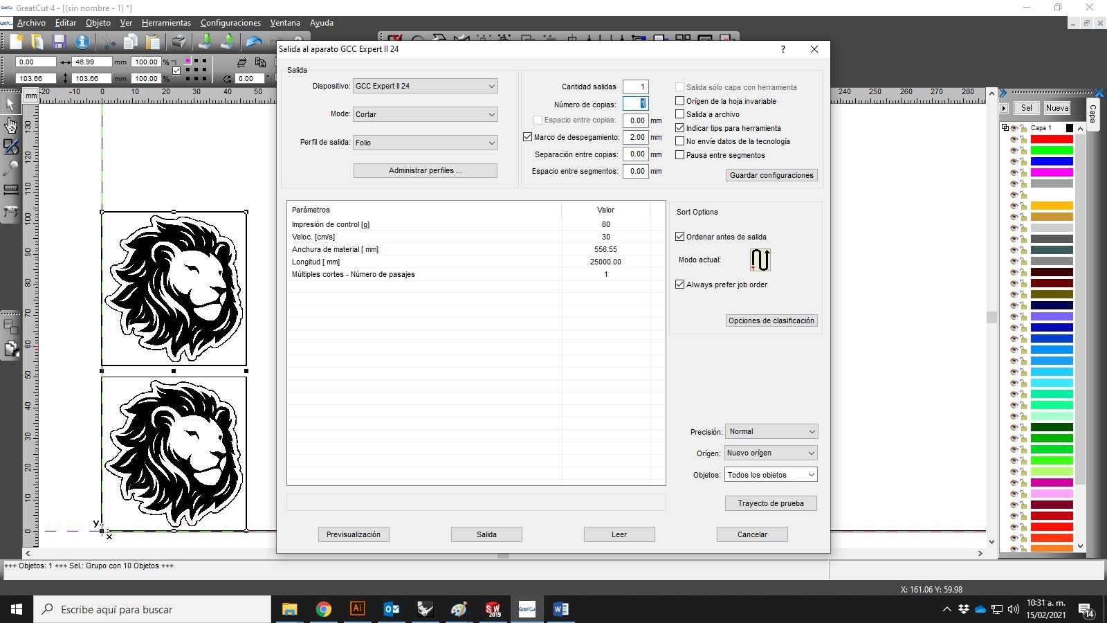
Using this machine is easy, it only requires a couple of parameter tests to adjust the pressure and speed depending on the material to be cut, the type of blade and the complexity of the figures to be made.
|
GCC Expert II Vinyl cutter Standard vinyl parameters.
|
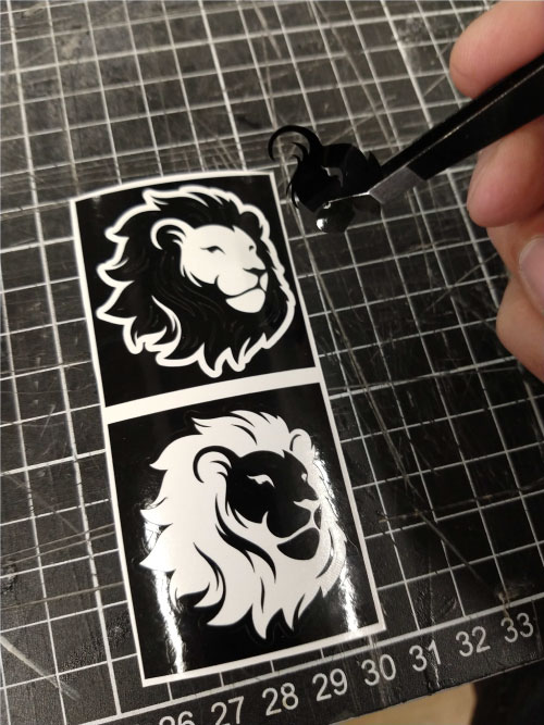
I cut two pairs, one on white vinyl and one on black vinyl, then I started weeding taking care of the fine details.
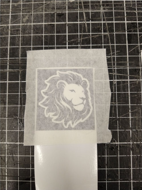
After weeding I had to move the front decal to the backing silhouette so first I used some painters tape as transfer tape (we had clear transfer tape but it's quite expensive so I wanted to make a test with another option).
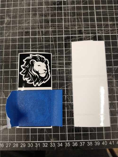
It was a bit difficult due to the strength of the glue and the low visibility it offers, but I was able to get my vinyl correctly applied.
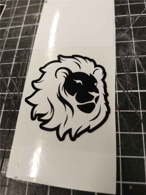
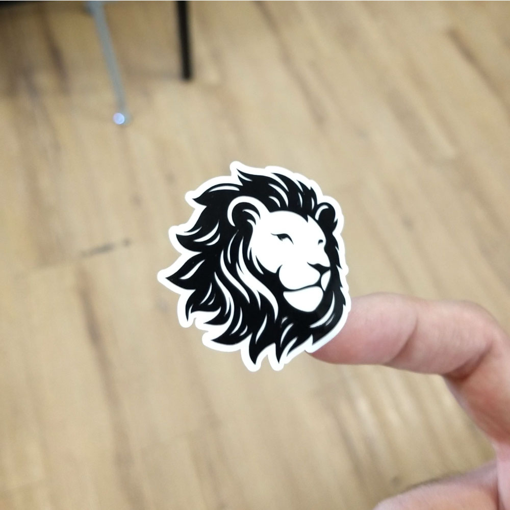
In my opinion the white backing with the black details looked better on my laptop, for this reason I was much more careful with the second sticker and I tried the transfer tape.
I must admit that the result was amazing.
Files
You can download the Solidworks files here: 01, 02, press-fit template.
You can download the construction kit .DXF file here.
You can download the sticker .AI file here.
|
For this assignment I:
|