How to make (almost) anything.
CAD / CAM
The design involves four elements: serial planes of acrylic discs, two acrylic boxes, an inner one to hold the LED strips and an outer one to hold all the discs in place, and a 3D printed base. For the body of the device I originally used a 3D printed cylinder with moving discs but realized that it took too much manufacturing time and it really was not essential that it had rotating elements so I opted for a structure that could be laser cut instead. I have used acrylic to make laser engraved lamps and I have always liked the effect that it generates when projecting light on its edges, so it was the material that I chose, and I left the 3D printing only for the base to be able to make a hollow piece that contained inside the board.
Computer aided design
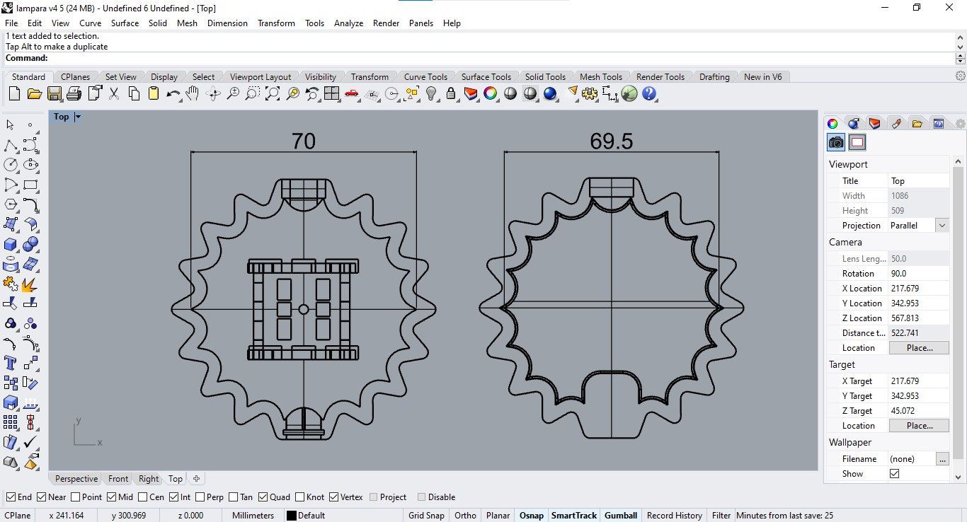
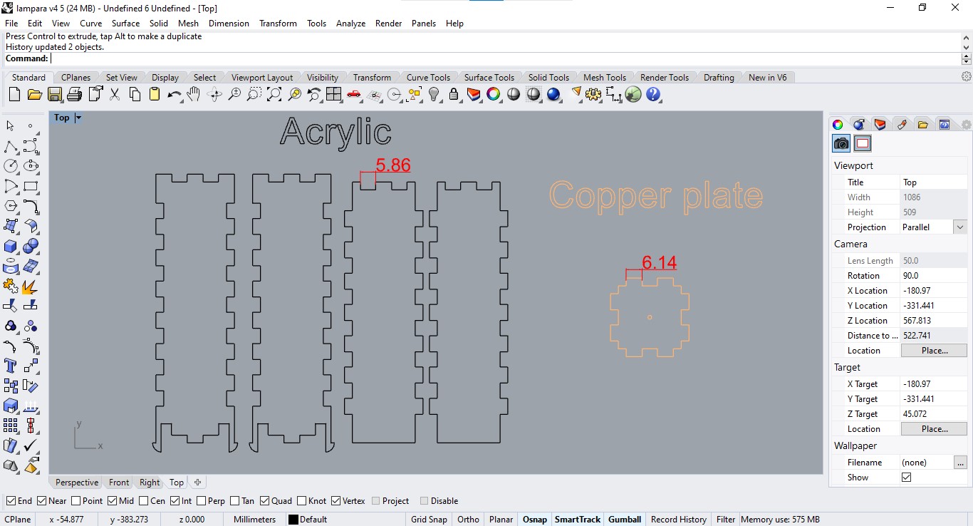
After some hand sketching I used Rhino to 2D model the disks and then the entire 3D structure.
Additive fabrication
3D printing of the base for the lamp that contains the PCB inside.
Subtractive fabrication
Laser cutting of the acrylic discs that generate the optical effect in the lamp.
Manual assembly of the whole acrylic set.
Evolution of the design
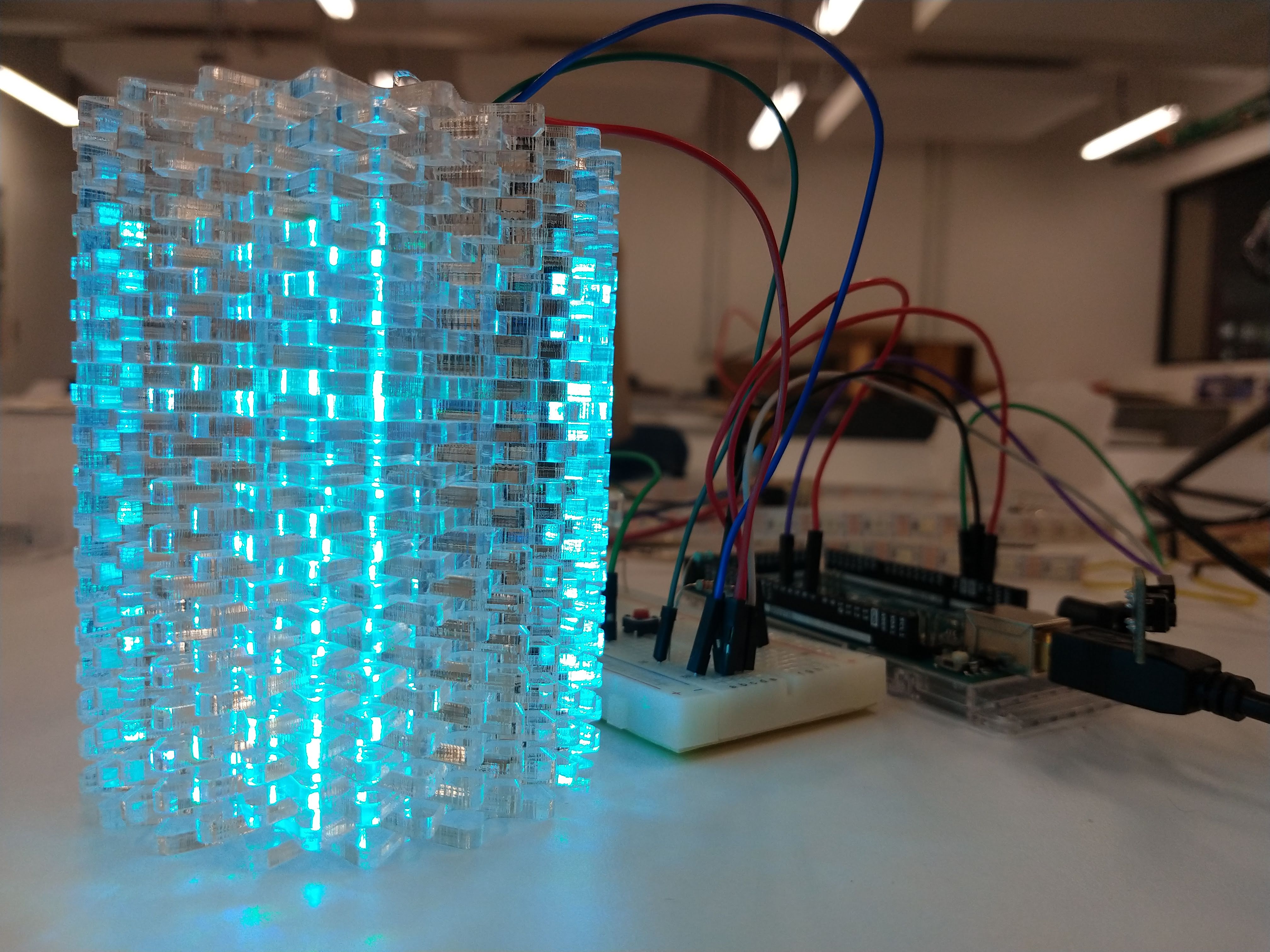
As soon as I decided on the shape that the device would have according to the lighting I needed, I made a box containing neopixels and placed acrylic discs around its perimeter so that the lighting was projected on its edges.
I printed a container for the board and another for the button. I included pressure assemblies between the 3D printed parts, for which I considered 0.5mm tolerance between them but this was too much, the joints were weak and the laser cut pieces fell off at the slightest movement.
This first prototype served as a reference to adjust the tolerances in later versions, I realized that the tolerances between parts that are printed to be assembled works well at 0.3mm.
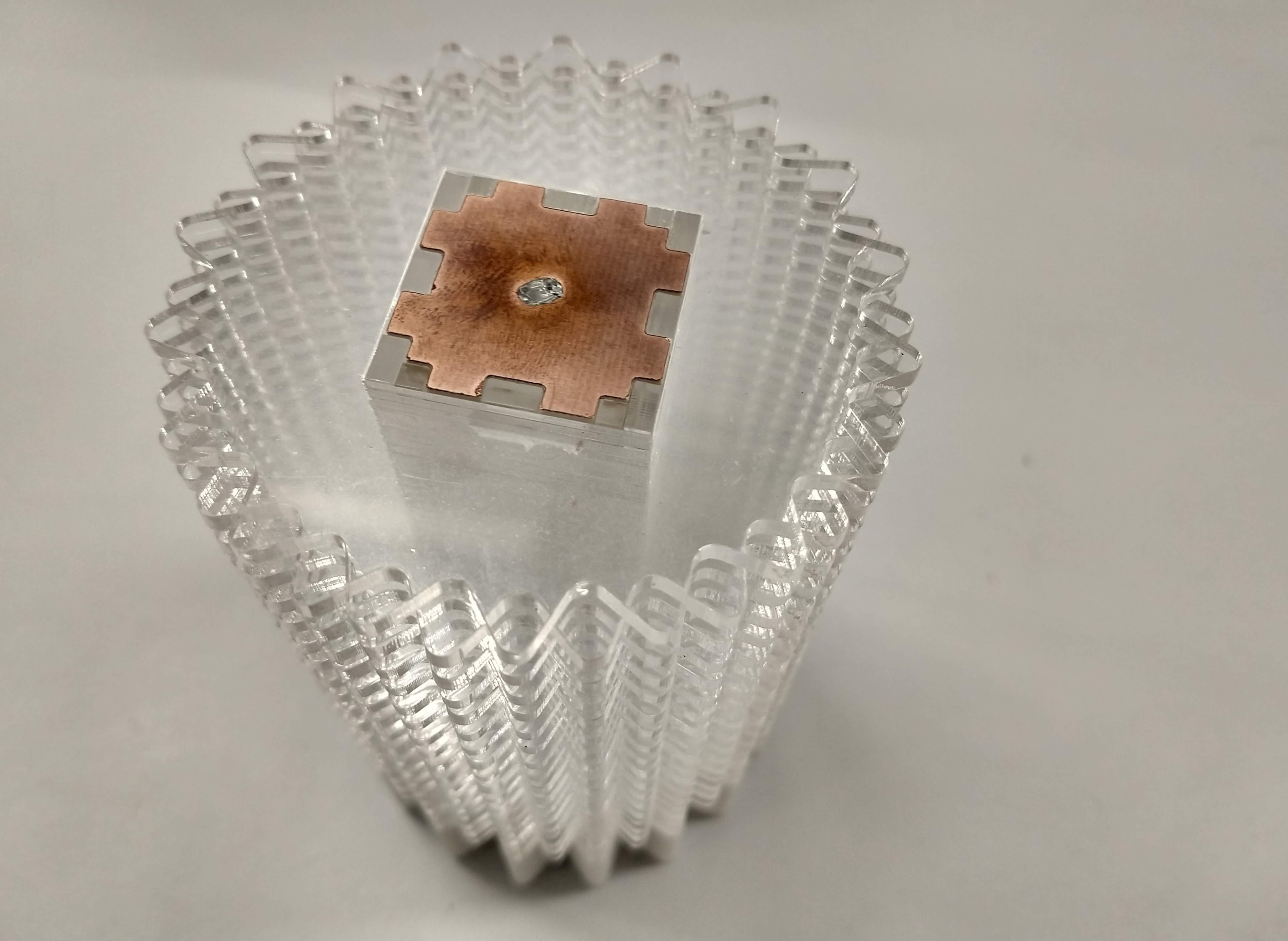
To improve the user experience I changed the button for a capacitive sensor using a copper plate. After some tests, I decided to integrate the capacitive sensor on the top of the neopixel container box, avoiding incorporating additional parts and obtaining a much cleaner design.
It is important to consider the tolerance fitting as the final measurements in laser cut pieces are slightly different from those cut in the Roland cnc (even if the cut is made along the outside of the line and setting the exact diameter of the router bit in the software), so I had to make an 0.28mm offset on the Roland piece to get a firm joint.
To assemble the acrylic box to the printed base I used cantilever snap joints in conjunction with press fit joints: two of the four box walls have these long tabs that run inside the base and lock at the end, as well as the center rectangle that functions as a snap guide on it's four sides.
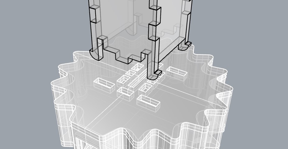
The same joint system is used on the two boxes, one for the acrylic discs and one for the neopixels (these are attached using double sided tape on the box wall).
The cables go inside the holes in the base and can be soldered directly to the board from the back or to the edges of the pins (for this reason the pins are installed with an excess at the bottom), this way the board does not lose the possibility of being programmed again.
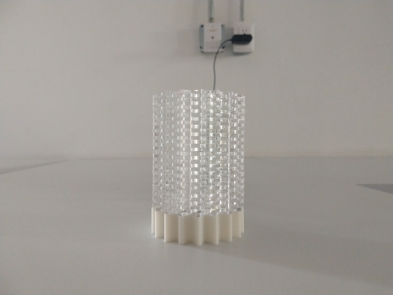
Final device
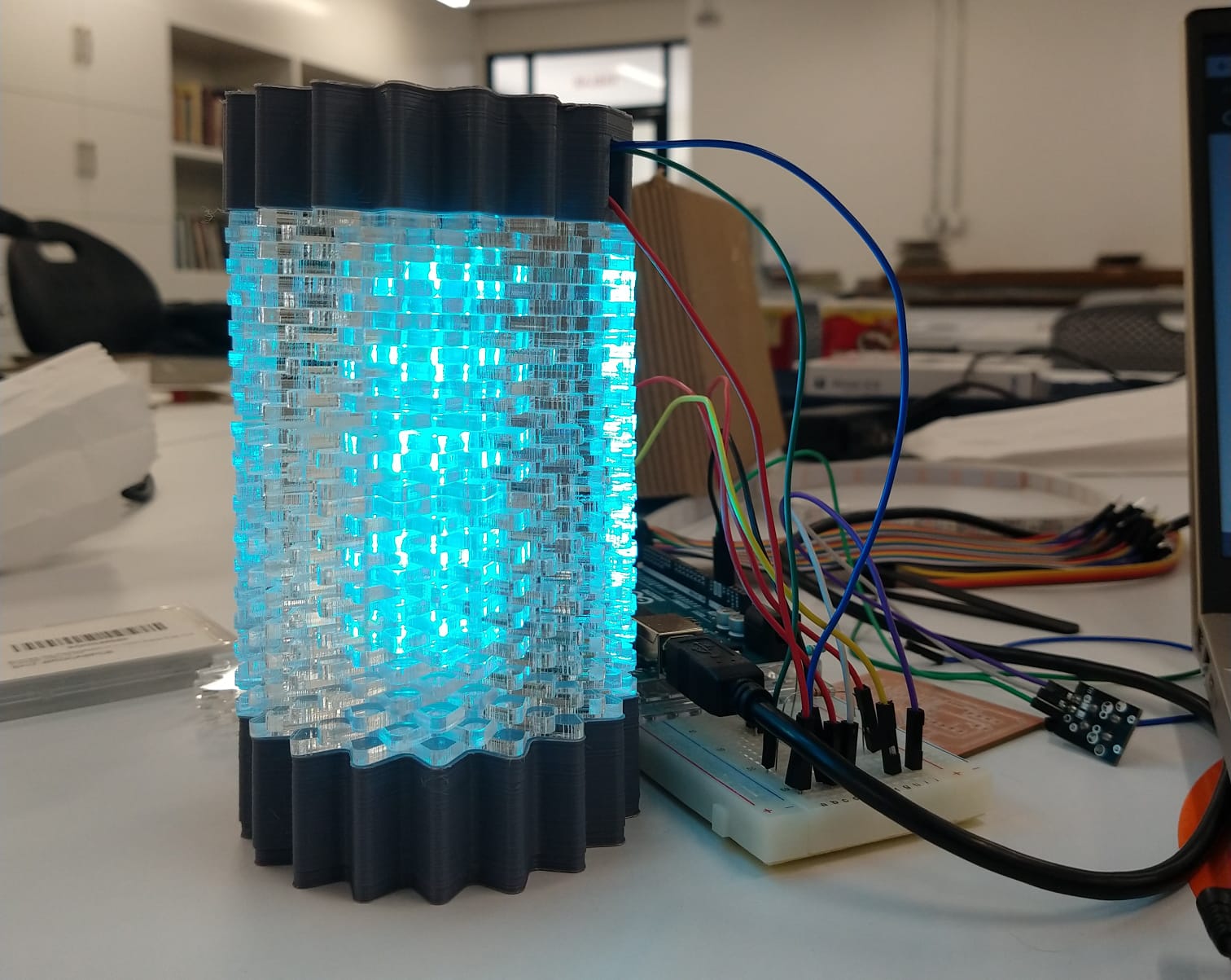
The final model uses press fit assemblies. Simply plug in the power adapter to turn on the device and touch the sensor on the top to switch between functions or turn off the light.
|
Downloads |