4. Computer Controlled Cutting
I. Vinyl Cutting
For the first part of this week’s assignment, we were required to create something using the vinyl cutter. Previously, I believed that the vinyl cutter was simply a tool to make stickers, and was overall a obsolete tool, but after watching the video lecture, my perspective changed. Through seeing applications and different projects, I was informed of the range of uses for this machine, such as for electronics, advanced origami/ folding, and more ,and how it is not just a “sticker making machine.”
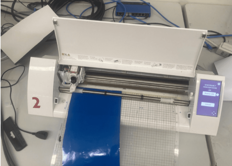
To create the vinyl stickers, I used our labs Silhouette Cameo 2 with Silhouette Studios and Corel Draw. First, I decided to make the finder icon from the MacOS because the application has always bothered me in the operating system because it cannot be closed. At the Charlotte Latin Fab Lab each year the group applies their stickers to the same window outside our teacher’s office. Therefore, I thought it would be a great idea to add the sticker on the window, so it is always watching and will always be there.
To design the sticker, I first traced an outline using the spline tool in Corel Draw, and then I exported three separate SVGs to Silhouette Studios. For the stickers after attempt #1, the three SVGs were of the black base and then of the blue and grey face layers. Here is a brief workflow for cutting with the Silhouette Cameo:
(1) Cut the desired amount of vinyl out. (2) Align and press the vinyl down on the cut mat. (3) Align the cut mat in with the arrows and press load cut mat. (4) Download and open the SVG into the software or trace a PNG or JPEG using its trace tool. (5) Go to the cut section of the software and select all objects/lines you want the vinyl cutter to cut. Finally adjust the settings and send it over to the vinyl cutter.
Attempt 1

The first design clearly did not come out as expected because the original black elements were separate cutouts and they could not be perfectly placed. To fix this issue I considered either creating one black base sticker, rather than individual black cutouts, or offsetting the black parts.
Attempt 2
In contrast to my first attempt this was a colossal improvement; however, applying the top grey and blue layers was still difficult. Originally, I had trouble aligning the different layers of the sticker, thus I created an all black piece for the base and used clear transfer paper instead in order to line up the pieces better.
Workflow for Weeding and Applying Vinyl:
(1) Use an exacto knife to remove any vinyl that you do not want in your sticker; this process is commonly referred to as weeding. (2) Cut out transfer paper and press over the weeded vinyl and then press with a scraper tool. (3) Take the vinyl sticker off the back paper and onto another piece of vinyl or a surface
Attempt 3

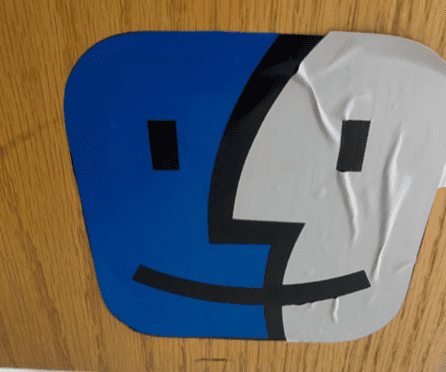
Still had issues with alignment, but that was simply a matter of practice. I also noticed a new problem with air bubbles forming between the layers of vinyl.
Attempt 4
In my third attempt while the application of the top vinyl layers improved, I still faced the issue with air bubbles between the black base layer and the top layers. In attempts to lessen this issue, I used an exacto knife to burst any large or noticeable bubbles and then briefly used a heat gun over the vinyl to remove them. Although this sticker was fine, I still wanted to try one more time but smaller and splayed down better.
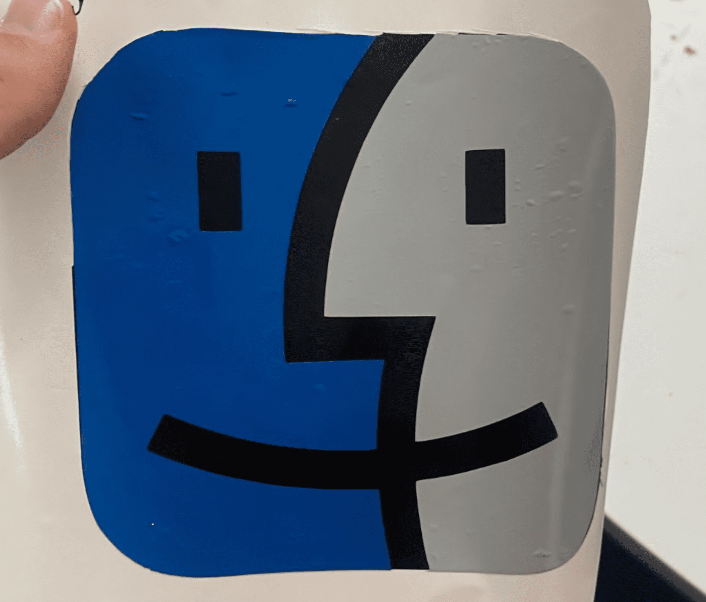
Final Sticker
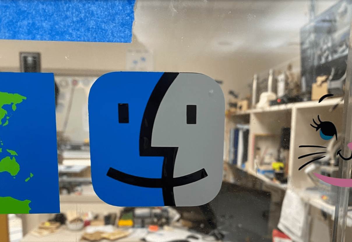
Overall, I think the sticker came out well despite the air bubbles. The use of the heat gun and exacto knife to remove the bubbles was effective, but it did not entirely make them disappear. I also made it smaller to make the vinyl easier to apply and also the previous stickers were massive (~ 8” x 8”).
II. Parametric Design Construction Kit
In the second part of this week’s assignments, I learned about parametric design when modeling. Essentially, parametric design means to use variables or equations for the value of sizes, rather than manually entering them. If you want to change the dimension of multiple sizes (and perhaps more that are affected by the change), rather than going back through sketches and re-entering the values, you can simply change the variable’s value, which is more time efficient and useful for larger models.
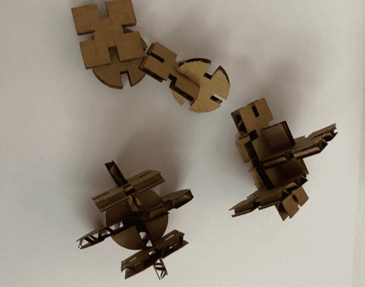
Design
First, I designed a basic parametric construction kit using squares and circles in Fusion 360. Below you can see the different variables used to create the squares of material width, the length of a side of the square, and the tab depth. If I wanted to use .25” thickwood opposed to .125” thick cardboard, I could simply edit the parameter for the width variable rather than individually editing 64 values for the tab width in the design.
For further information on parametric design, I referenced this Autodesk Fusion 360 parametric design tutorial
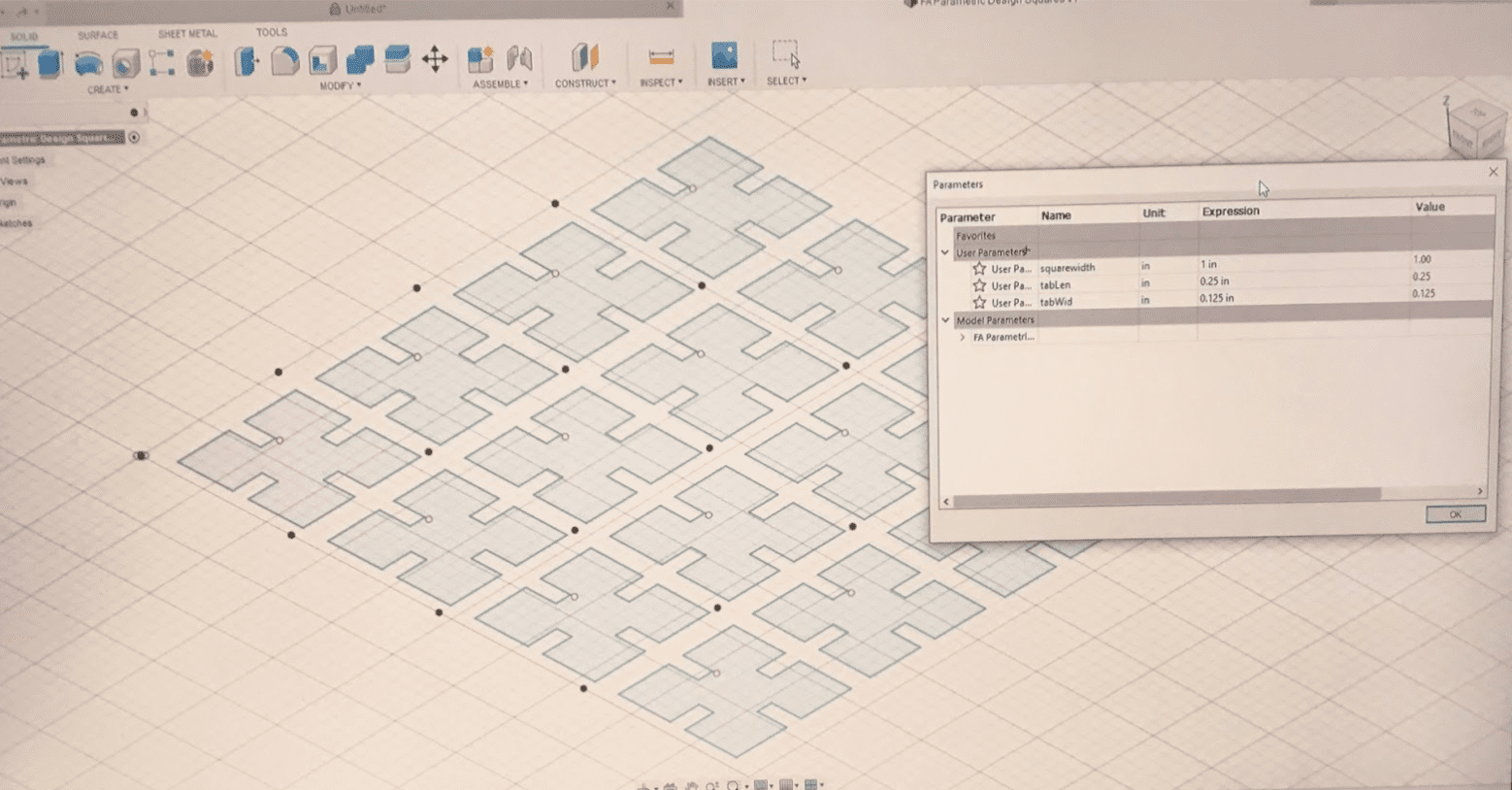
Fusion 360 Parametric Construction Kit Squares
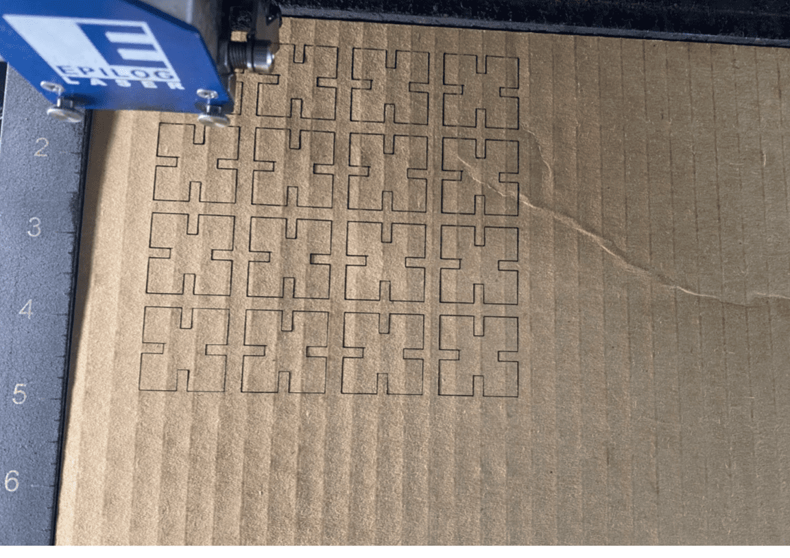
| Job Type | Material Type | Material Width | Laser Type | Speed | Power | Frequency | Work Area |
|---|---|---|---|---|---|---|---|
| Vector | Cardboard | 0.125” | CO2 | 25% | 65% | 50% | 30” x 20” |
III. Parametric Design Continued
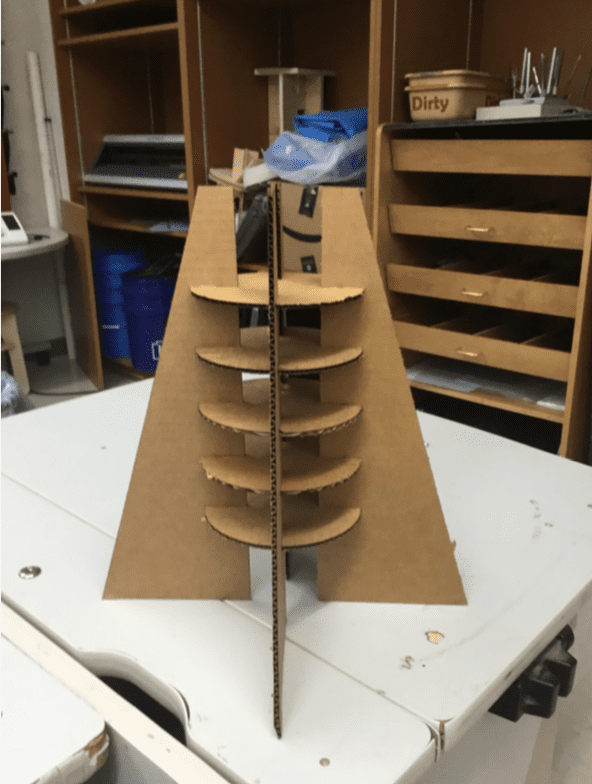
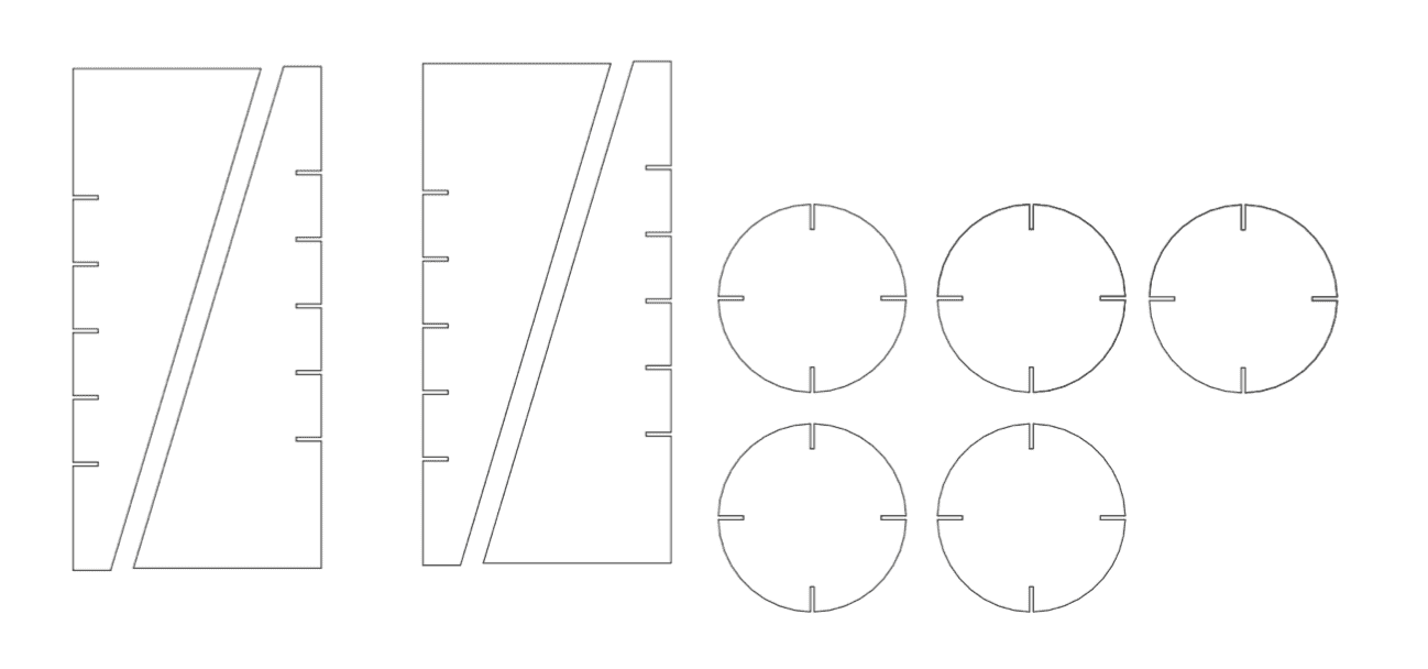
With my new skill of using parameters to easily scale models, I thought it would be interesting to apply them to create a small project. Consequently, I modeled a stand for a ball or some spherical object. This version of the stand was significantly smaller, as it is much more cost effective to prototype using less material. Additionally, the smaller model reduces the cut time of the material, which allows faster prototyping. However, a downside to parametric modeling for prototyping is that some design elements can be overlooked when scaling, and depending on the type of project, testing can be more difficult.
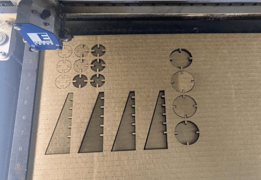
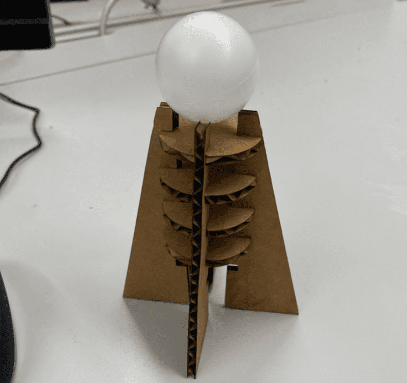
Scaling the Model:
Here are the variable parameters for my scaled stand:
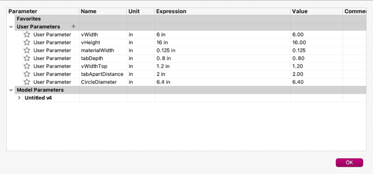
A major takeaway from modeling parametrically was that constraints are imperative when changing parameters. Initially, when I edited my sketch dimensions through changing variables, the sketch would not change as intended due to lack of constraints on for example distance between tabs. Additionally, when exporting DXFs from Fusion 360, construction lines would be included as well, so prior to exporting the file to laser cut, construction lines would have to be deleted. This posed a potential issue, as several of my constraints involved construction lines, but the dimension tool functioned well as an alternative method.
IV. Group Project
Visit our Charlotte Latin Fab Academy Group Website Here. During this week’s group assignment, I was responsible for finding and defining laser cutting key terms with Drew Griggs and Graham Smith, as well as updating the website for the project with Teddy Warner. A more detailed explanation and documentation is available on the group site; however, in short, our group determined the optimal laser cutter settings for plywood and cardboard and reviewed how to operate the machinery.