WEEK 12: Output devices
This week's assignment was about testing some output devices, and measuring their consumption.
Group assignment:
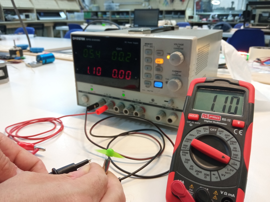
For the group assignment, we had to measure the electrical consumption of some outputs, so we measured it in some of the outputs that we were using:
LCD panel:
Electrical Consumption: 20 mA

RGB LED STRIP (144 LEDS):
Electrical Consumption: 170-800 mA

Small DC motor:
Electrical Consumption: 1100 mA
Individual assignment
For the individual assignment, I decided to test something that I might use in my final project, so I chose a RGB LED in order to understand how they work.
I also wanted to understand the operation of a Mosfet, so I used the same board to place one on it.
As a "base" board, I used the one that I made for the input devices week with and ATTiny 1614, so I only had to design and produce the board with the outputs and connect it to the base board.
The base board with the ATTiny 1614:

The RGB LED that we have at the lab has the following specifications, that can be checked in the datasheet.
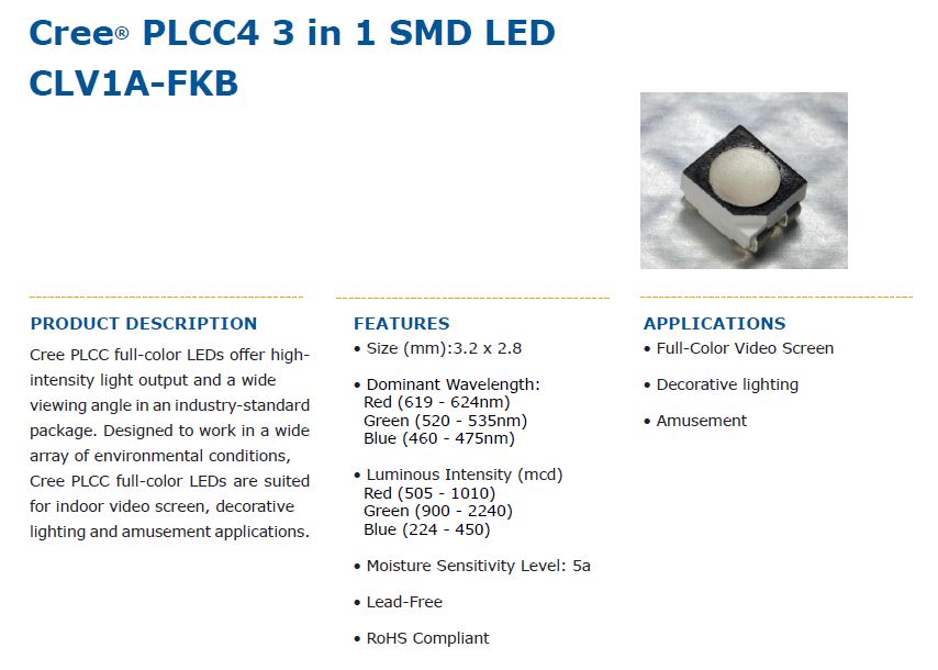

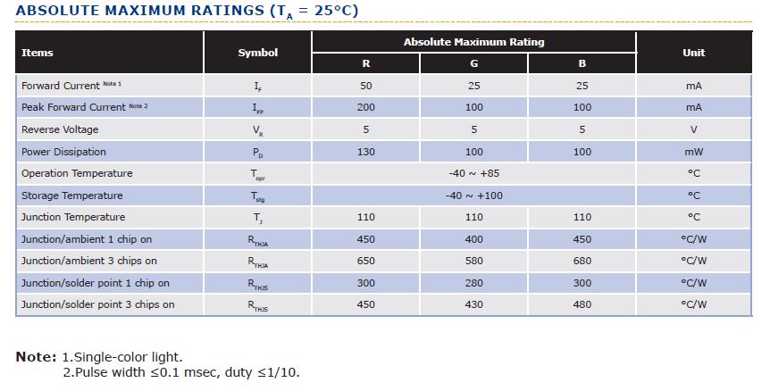
With this information, I calculated the resistors for the three different colours:
Resistor calculation:
- RED: 5V & 50mA = 100 Ω
- GREEN: 5V & 25mA = 200 Ω
- BLUE: 5V & 25mA = 200 Ω
The Mosfet I used is a P-Channel one with the following features that can be checked in the datasheet.

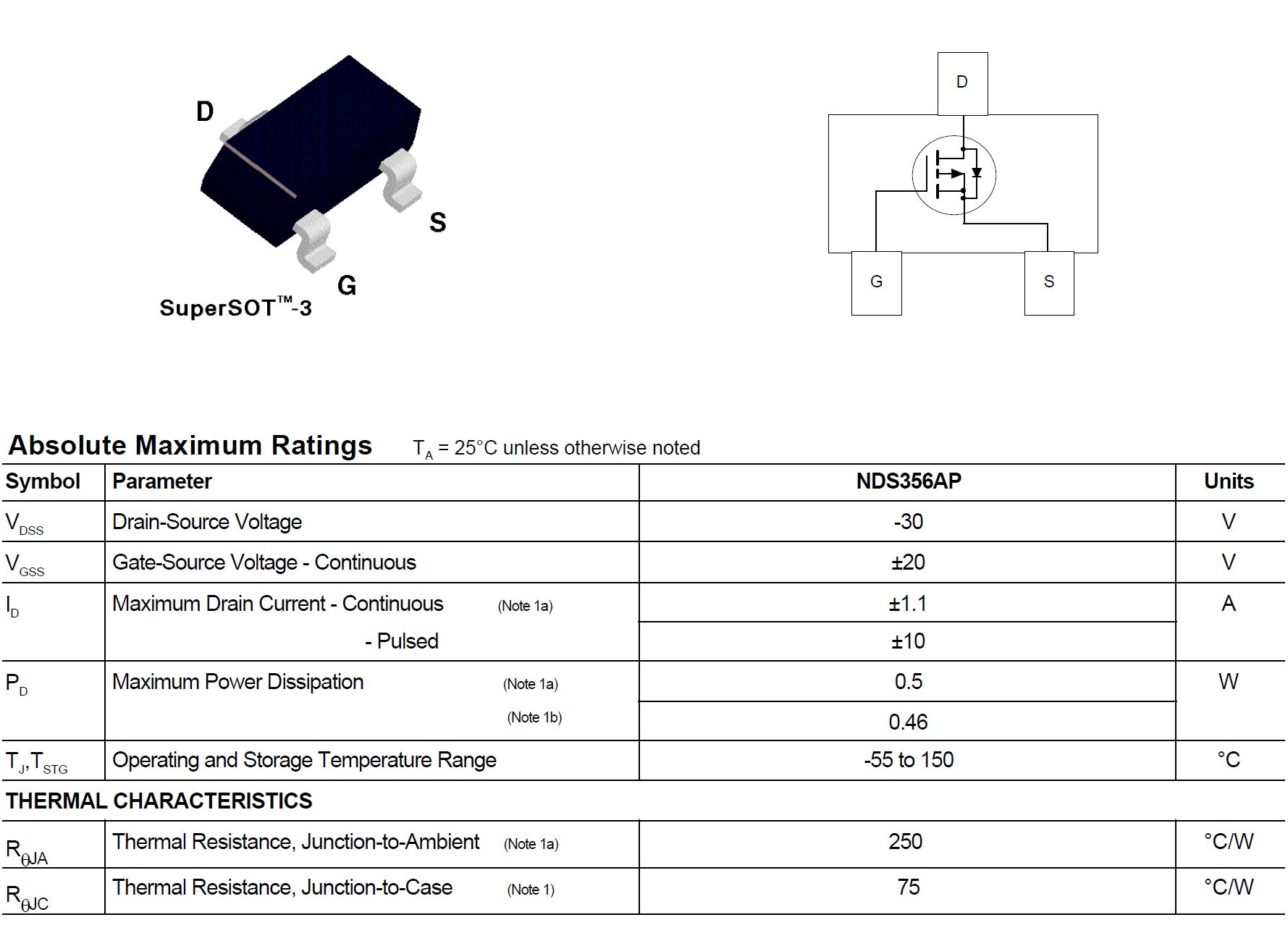
The scheme I followed to connect it:

Then I designed the scheme in KiCad.
The board designed has a connector to connect with the main board with 6 pins, that are:
- Blue LED
- Green LED
- Red LED
- PIN to control the Mosfet
- VCC 5V
- GND
I placed the RGB LED with the required resistors (as we didn't have 220 ohm resistors in the lab, I used two of 100), and the Mosfet with the required resistors to a 2-pin connector to connect whatever output I want to it. As the Mosfet is a P-Channel, it operates giving VCC to the output. I also placed a diode as it's showed in the scheme.

For the PCB layout, I placed all the components and for the traces I used standard 0,40 mm width except for the output of the Mosfet where I used 0,8mm.
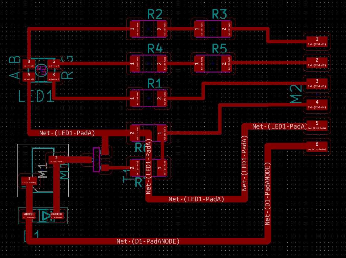
And I milled it in the way I explain in the electronics design week.

And I soldered all the components:

Once I had the board ready, I connected it to the base board with the ATTiny 1614.
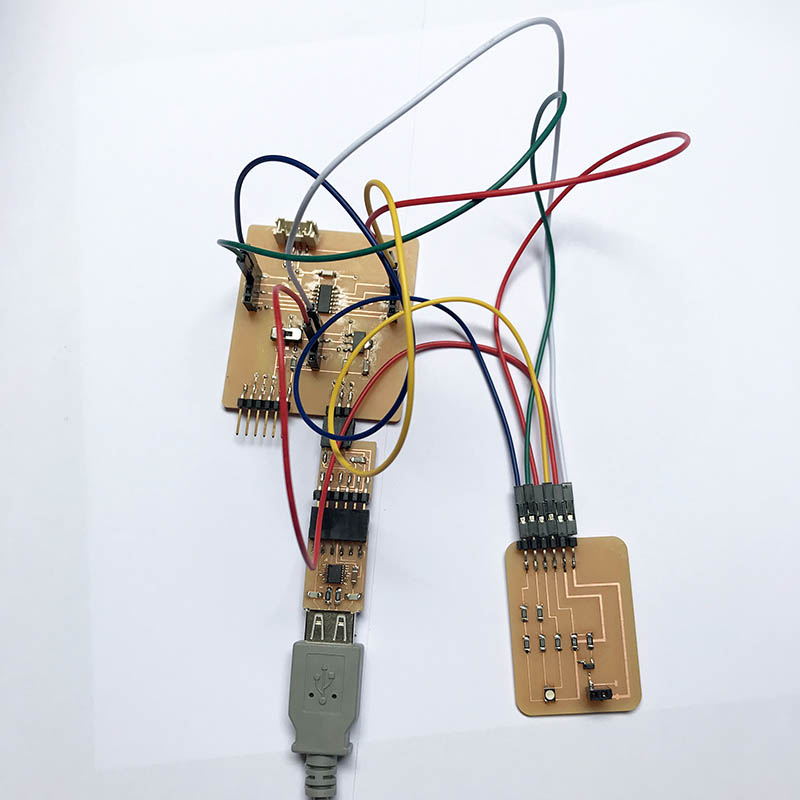
I connected it like this:
- GROUND <=> GROUND
- VCC 5V <=> VCC 5V
- LED RED PIN <=> PIN 10
- LED GREEN PIN <=> PIN 1
- LED BLUE PIN <=> PIN 0
- MOSFET PIN <=> PIN 9

In order to test the LED I used the following simple code, where I do a blink of each colour:
  int R = 10;
  int G = 1;
  int B = 0;

  void setup() {
    pinMode(R, OUTPUT);
    pinMode(G, OUTPUT);
    pinMode(G, OUTPUT);
  }

  void loop() {
    /*RED*/
    digitalWrite(R, LOW);
    digitalWrite(G, HIGH);
    digitalWrite(B, HIGH);
    delay(1000);
    /*BLUE*/
    digitalWrite(R, HIGH);
    digitalWrite(G, HIGH);
    digitalWrite(B, LOW);
    delay(1000);
    /*GREEN*/
    digitalWrite(R, HIGH);
    digitalWrite(G, LOW);
    digitalWrite(B, HIGH);
    delay(1000);
  }
Then I tried to made some colours by mixing the intensity of the different channels:
  int R = 10;
  int G = 1;
  int B = 0;

  void setup() {
    pinMode(R, OUTPUT);
    pinMode(G, OUTPUT);
    pinMode(G, OUTPUT);
  }

  void loop() {
    /*DARK RED*/
    analogWrite(R, 0);
    analogWrite(G, 159);
    analogWrite(B, 170);
    delay(1000);
    /*FAINT WHITE*/
    analogWrite(R, 220);
    analogWrite(G, 220);
    analogWrite(B, 220);
    delay(1000);
    /*ORANGE*/
    analogWrite(R, 0);
    analogWrite(G, 104);
    analogWrite(B, 255);
    delay(1000);
  }
In order to test the Mosfet, as I didn't have any other outputs at home, I just made a simple blink and checked that it worked in the output of the Mosfet.
  void setup() {
    pinMode(9, OUTPUT);
  }

  void loop() {
    digitalWrite(9, HIGH);
    delay(1000);
    digitalWrite(9, LOW);
    delay(1000);
  }
Files:
KiCad files
PNG for the traces
PNG for the fill
PNG for the outcut