
Computer Aided Design
HOW DOES CAD WORK?
This is the content we had covered this week:
W2 - Computer-Aided Design
- 2D Design Tools: Vector vs Raster
- 3D Design tools: Blender, Rhino & Fusion 360
- Parametric Design
- Many other tools to explore.
Assignment
- model 2D : raster & vector
- 3D: model, render, animate, simulate, …
- possible final project, compress your images and videos, and post it on your class page.
I created some more drawings and diagrams to explain this week’s concepts.
2D DESIGN TOOLS
RASTER VS VECTOR
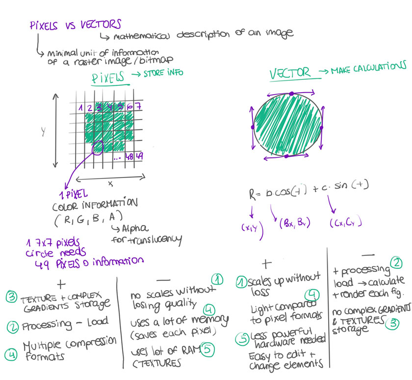
"Diagram showing the differences between Raster and Vector"
SOFTWARE & FILE FORMAT EXAMPLES
- RASTER: Photoshop, GIMP
- RASTER FILE FORMATS: .TIFF, .JPEG, .PSD, .GIF, .PNG
- VECTOR: Illustrator, Inkscape, CorelDraw
- VECTOR FILE FORMATS: .EPS, .AI, .SVG , .PDF , .CDR
IMAGE TYPES & SPECS
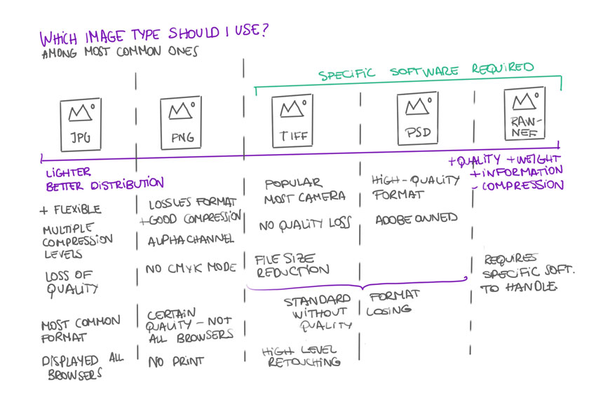
"Diagram showing the different image types"
RESOLUTION VS PPI
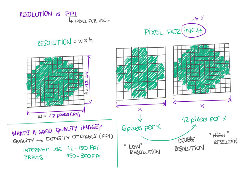
"Diagram showing the differences between Resolution and PPI"
CPU VS GPU
I’ve heard of the terms before but I decided to dig deeper to understand better the differents. The diagram was truly helpful in this particular case.
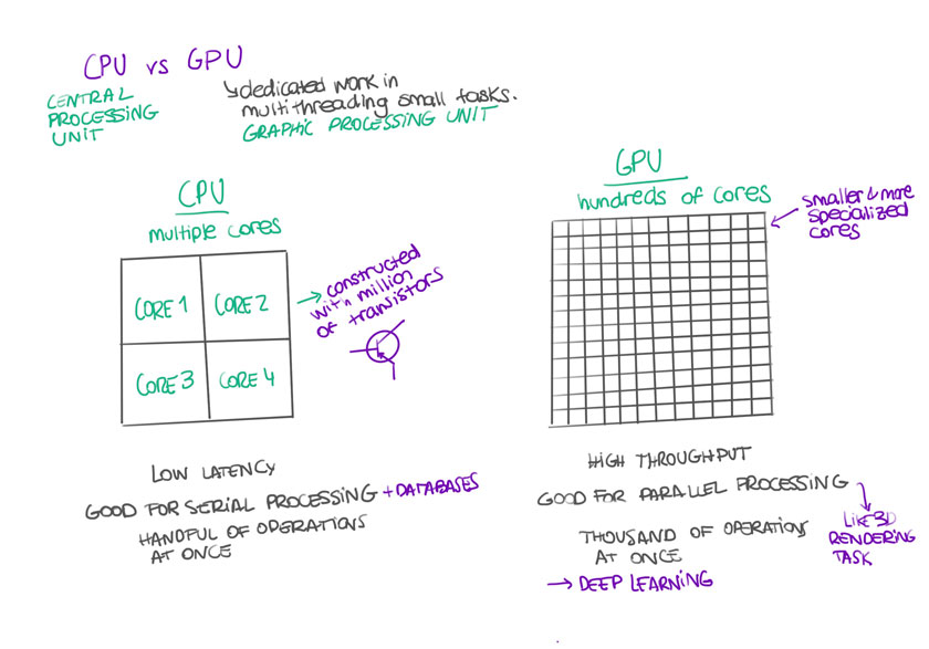
"Diagram showing the differences between GPU and CPU"
ASSIGNMENT | 2D
VECTOR: ILLUSTRATOR
I’ve been using illustrator for a couple of years, and to me it’s quite natural to draw vectors that later on could be used in very different applications. In this particular case, I decided to use tools such as Rotate, Copy and Pathfinder (boolean operations) to replicate a Lego Technic Gear.

"Vector Drawing of a Lego Gear using a raster image as a reference"
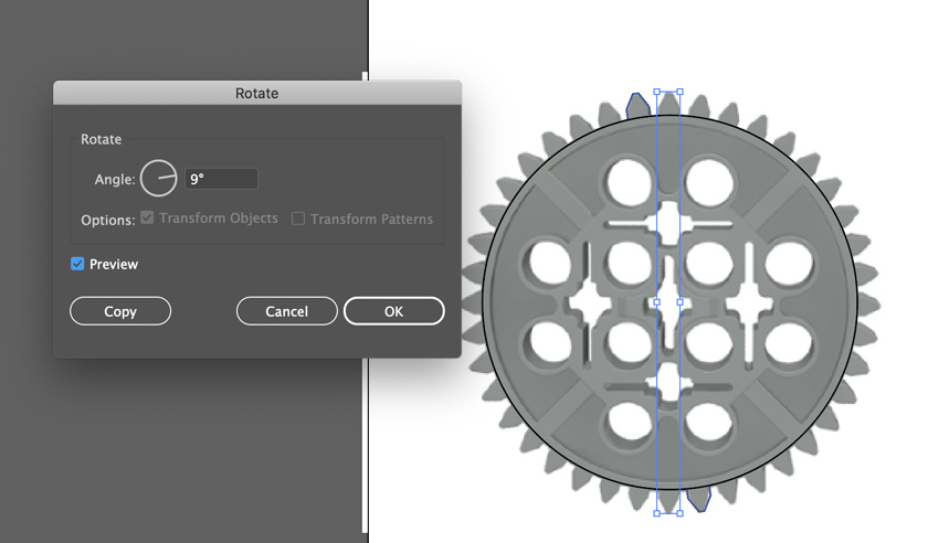
"Vector Drawing using Rotate Copy with a center rotation."

"Vector Drawing using Pathfinder tool (boolean operations)."
WHAT WENT WELL
Speed: Very fast due to familiarity with the software
Customization: Very easy to modify changing parameters within the toolsWHAT COULD BE BETTER
Accurary: Illustrator tangents are not very accurate.
RASTER: PHOTOSHOP
I’ve been using photoshop for a long time but it’s definitely not my fav. tool to draw or sketch. So I decided to grab the gear I’ve done in Illustrator and show the comparison between raster and vector.
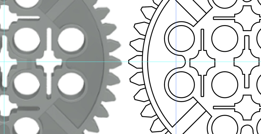
"Left: Raster Image vs Right: Vector"
3D DESIGN TOOLS
MESH VS NURBS
Before using any tool, knowing the difference between Mesh and Nurbs 3D models is key to understand the potential and capabilities of each tool.
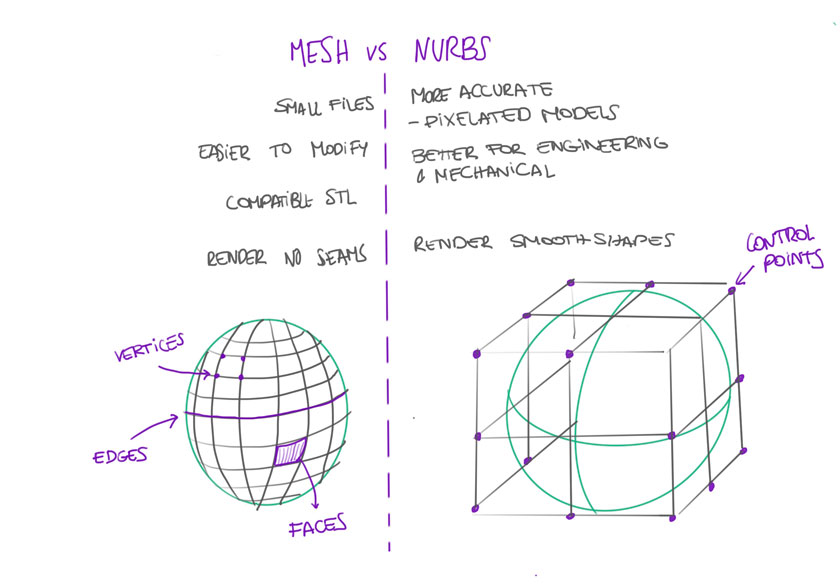
"Diagram showing the differences between Mesh and Nurbs"
ASSIGNMENT | 3D
3D MODEL: FUSION 360
Fusion 360 is a tool that I’ve been wanting to use for quite a long time. To be honest I thought that the learning curve was going to be lower, but still I enjoyed quite a lot using it. The prompt was the same than for my 2D assignment, the gear.
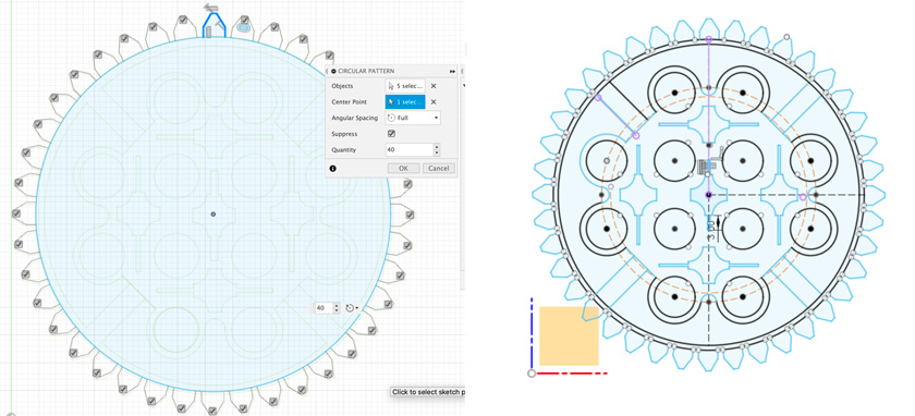
"Left: I imported an SVG to have a reference of the gear. I used different operations to build the main sketch. Right: Finished Sketch after multiple operations and constraints such as Symmetry, Equal, .."
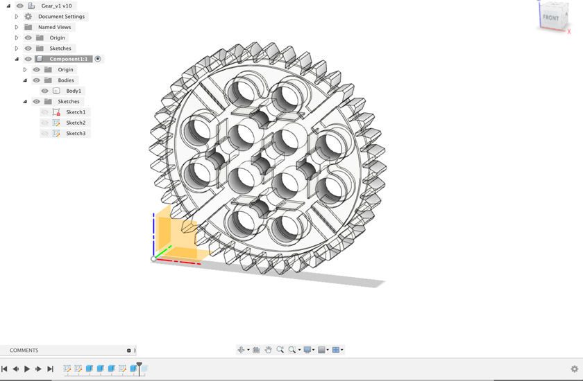
"I extruded the different layers of the sketch until I got the whole gear in 3D."
3D render: FUSION 360
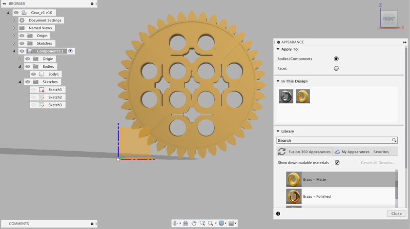
"I added Brass as a material for my Gear"
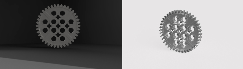
"Testing different Render settings"
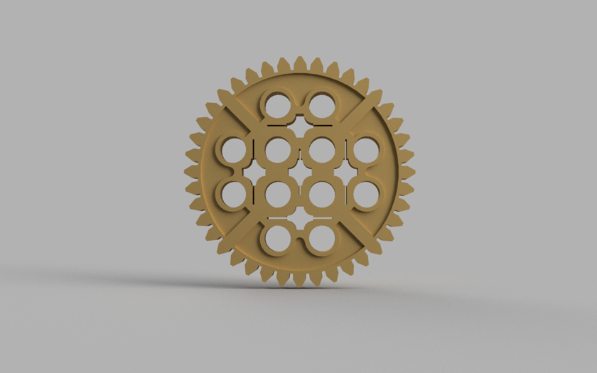
"Final Render with Final Quality"
"Animation done using Fusion 360"
"Fusion 360 Embedded 3d Model with final materials"
WHAT WENT WELL
Accuary: Quite Easy to be mathematically correct.
Versatility: Allows to develop every object to multiple outputs.WHAT COULD BE BETTER
Steep Learning curve: Having already design the object with another tool, I found myself quite slow on the process.
Animation: I wish the animation could be rendered at more quality and finesse.
BONUS TRACK
As I’m quite a newbie using CAD tools to do EXACTLY what I want, I decided to focus on Fusion 360 which was on my TO-DO list for so long!.
I’m sharing some experiments I did with other tools in the past.
OpenSCAD
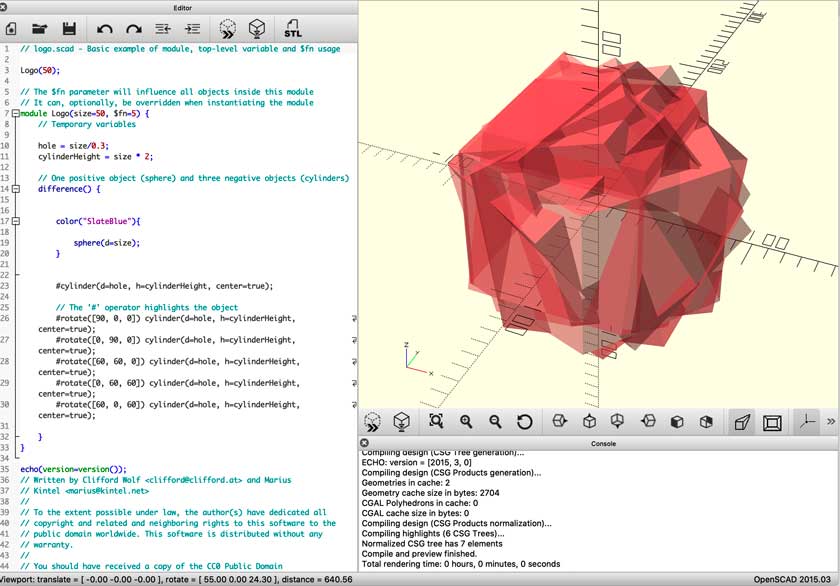
"OpenSCAD exploration using an example as a base"
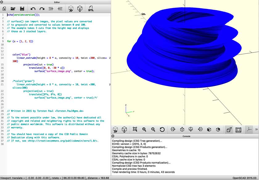
"OpenSCAD test"
CODE CHUNK
// logo.scad - Basic example of module, top-level variable and $fn usage

Logo(50);

// The $fn parameter will influence all objects inside this module
// It can, optionally, be overridden when instantiating the module
module Logo(size=50, $fn=5) {
    // Temporary variables

    hole = size/0.3;
    cylinderHeight = size * 2;

    // One positive object (sphere) and three negative objects (cylinders)
    difference() {


        color("SlateBlue"){

            sphere(d=size);
        }


        #cylinder(d=hole, h=cylinderHeight, center=true);

        // The '#' operator highlights the object
        #rotate([90, 0, 0]) cylinder(d=hole, h=cylinderHeight, center=true);
        #rotate([0, 90, 0]) cylinder(d=hole, h=cylinderHeight, center=true);
        #rotate([60, 60, 0]) cylinder(d=hole, h=cylinderHeight, center=true);
        #rotate([0, 60, 60]) cylinder(d=hole, h=cylinderHeight, center=true);
        #rotate([60, 0, 60]) cylinder(d=hole, h=cylinderHeight, center=true);

    }
}

echo(version=version());
// Written by Clifford Wolf <clifford@clifford.at> and Marius
// Kintel <marius@kintel.net>
//
// To the extent possible under law, the author(s) have dedicated all
// copyright and related and neighboring rights to this software to the
// public domain worldwide. This software is distributed without any
// warranty.
//
// You should have received a copy of the CC0 Public Domain
// Dedication along with this software.
// If not, see <http://creativecommons.org/publicdomain/zero/1.0/>.
"OpenSCAD exploration using an example as a base"
"OpenSCAD exploration using an example as a base"
CODE CHUNK
echo(version=version());

// surface() can import images, the pixel values are converted
// to grayscale and converted to values between 0 and 100.
// The example takes 3 cuts from the height map and displays
// those as 3 stacked layers.

for (a = [1, 2, 3])

    color("blue")
       linear_extrude(height = 8 * a, convexity = 10, twist =300, slices=300)
            projection(cut = true)
                translate([0, 0, -30 * a])
                    surface("surface_image.png", center = true);


    /*color("green")
       linear_extrude(height = 8 * a, convexity = 10, twist =300, slices=300)
            projection(cut = true)
                translate([8*a, 8*a, 0])
                    surface("surface_image.png", center = true);*/


// Written in 2015 by Torsten Paul <Torsten.Paul@gmx.de>
//
// To the extent possible under law, the author(s) have dedicated all
// copyright and related and neighboring rights to this software to the
// public domain worldwide. This software is distributed without any
// warranty.
//
// You should have received a copy of the CC0 Public Domain
// Dedication along with this software.
// If not, see <http://creativecommons.org/publicdomain/zero/1.0/>.
WHAT WENT WELL
Fun:I enjoyed testing stuff.
Exploration: It allowed me to develop forms otherwise I wouldn’t have.WHAT COULD BE BETTER
Steep Learning curve: I believe it’s quite an interesting tool, however it’s challenging to master.
Rhino + Grasshopper
WHAT WENT WELL
Outcomes:I enjoyed testing stuff.
Potential: I can see myself using the tool in many different scenariosWHAT COULD BE BETTER
More background needed: I think knowing more Rhino would be handy.
FINAL PROJECT
This week I decided to learn the tools properly, rather than formalizing something that will potentially change next week. I hope that more familiarity with 3D modelling tools will ease the pace in later stages.
Lastly, I’ve been trying to re-organize the pipeline that I plan on following the next couple of weeks and do some design methodologies. TBD.