Sensors VOL 1
SENSORS VOL.1
W10 - SENSORS FOR GROUP ASSIGNMENT
The goal I set to myself was to work/ understand a sensor/ set of sensors a day during a month (all the ones that came in a set produced by Elegoo). This process took place during an Independent study summer 2018.
I did a brief research on each sensor, took some notes, and finally tried to create a quick prototype for each one.
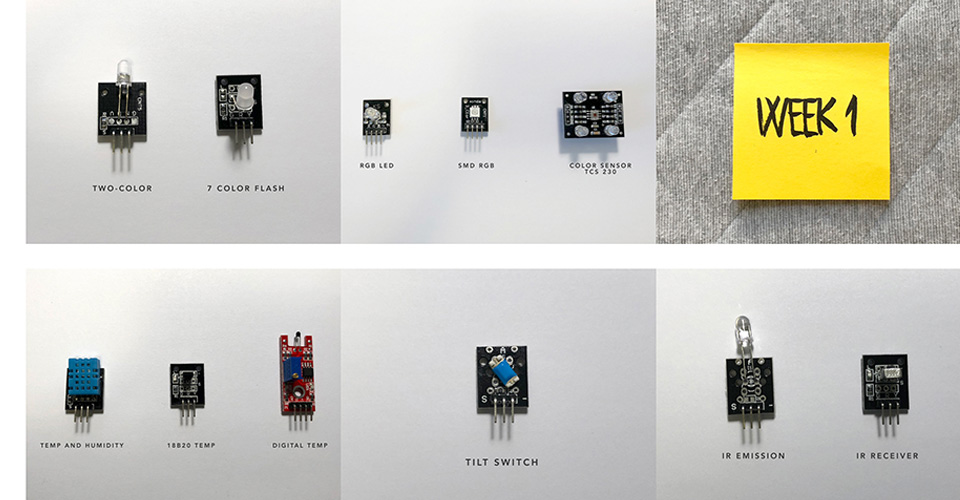
WEEK 1
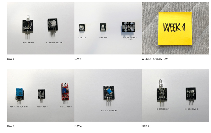
"Image showing all the sensors tested on week 1 of research"
DAY 1
RGB LED + SMD RGB + COLOR SENSOR TCS 230
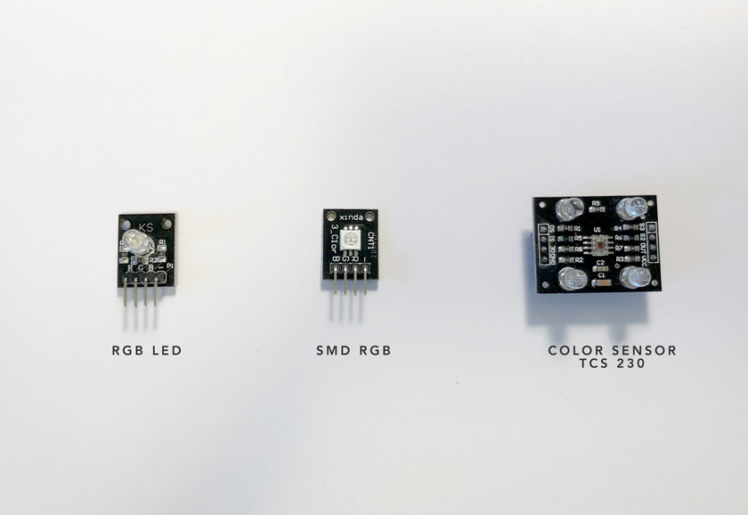
MODULES STUDY
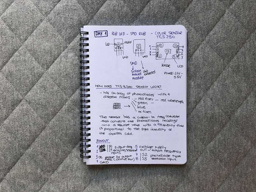
TESTING RGB LED + SMD RGB
#define BLUE_LED_DIO 5     /* Select the DIO for driving the BLUE LED */
#define RED_LED_DIO 7       /* Select the DIO for driving the RED LED */
#define GREEN_LED_DIO 6    /* Select the DIO for driving the GREEN LED */

/* Initialise serial and DIO */
void setup()
{
  /* Configure the DIO pins used by the analogWrite PWM function */
  pinMode(BLUE_LED_DIO, OUTPUT);
  pinMode(RED_LED_DIO, OUTPUT);
  pinMode(GREEN_LED_DIO, OUTPUT);
}

/* Main program loop */
void loop()
{
  int k;

  /* Slowly reduce the red LED's intensity and at the same time
     increase the green LED's intensity */
  for (k = 0; k <=255; k++)
  {
    analogWrite(RED_LED_DIO,255 - k);
    analogWrite(GREEN_LED_DIO, k);
    delay(10);
  }

  /* Slowly reduce the green LED's intensity and at the same time
     increase the blue LED's intensity */
  for (k = 0; k <=255; k++)
  {
    analogWrite(GREEN_LED_DIO,255 - k);
    analogWrite(BLUE_LED_DIO, k);
    delay(10);
  }

  /* Slowly reduce the blue LED's intensity and at the same time
     increase the red LED's intensity */
  for (k = 0; k <=255; k++)
  {
    analogWrite(BLUE_LED_DIO,255 - k);
    analogWrite(RED_LED_DIO, k);
    delay(10);
  }
}
PROTOTYPE PROPOSAL
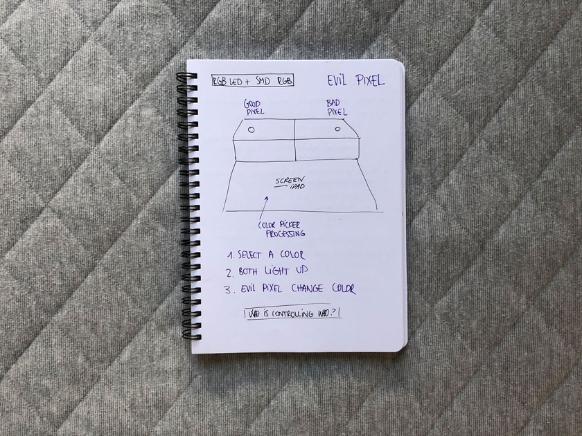
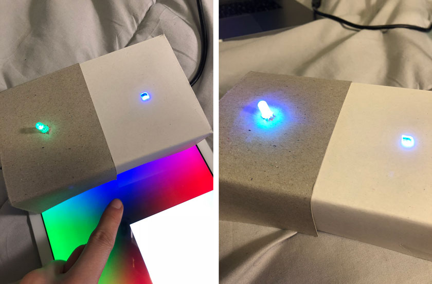
CODE
Download RGB LEDS project arduino code
Download RGB LEDS project processing code
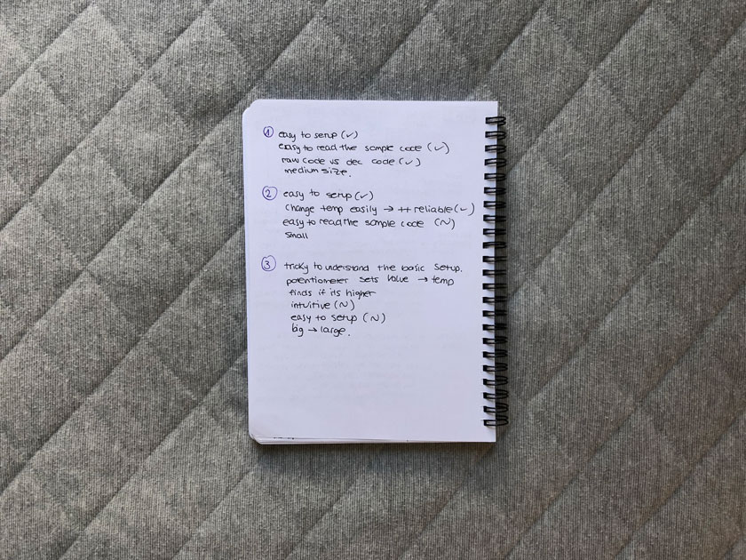
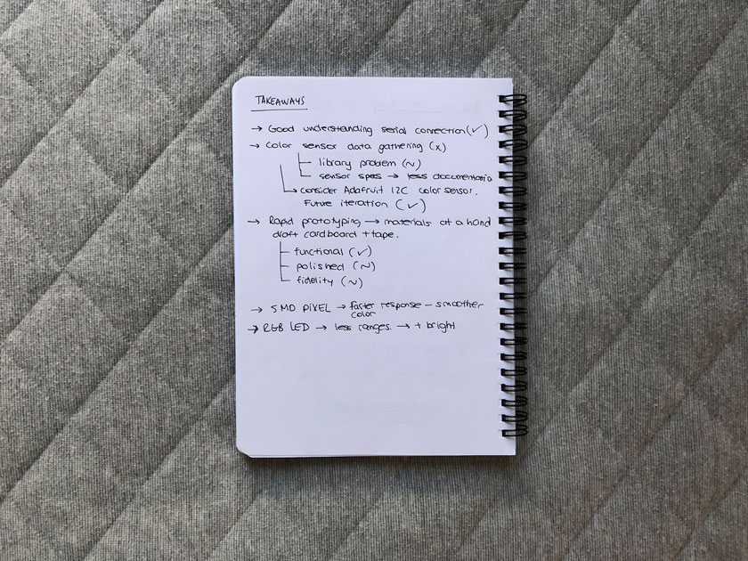
TAKEAWAYS
DAY 2
TWO-COLOR LED MODULE + 7 COLOR FLASH
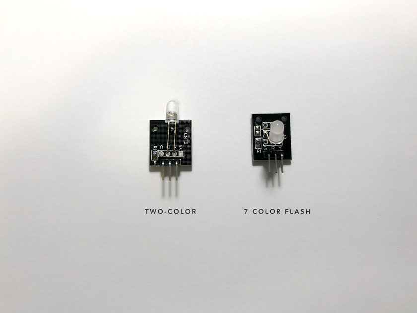
MODULES STUDY
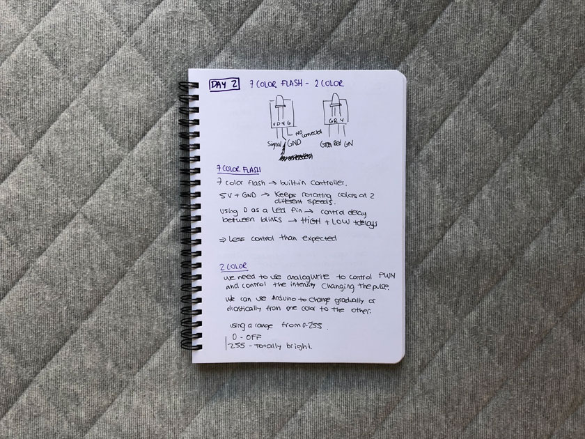
7 COLOR FLASH TEST
// 7 color flash LED SKETCH

int Led = 13;

void setup ()
{
  pinMode (Led, OUTPUT); // Initialize LED
}

void loop ()
{
  digitalWrite (Led, HIGH); // LED ON
  delay (4000); // Wait 4 seconds
  digitalWrite (Led, LOW); // LED OFF
  delay (2000); // Wait 2 seconds
}
2 COLOR LED TEST
//2 COLOR LED SKETCH

// Arduino test code for KY011

int redpin = 11; // select the pin for the red LED
int greenpin = 10; // select the pin for the green LED
int val;
void setup () {
   pinMode (redpin, OUTPUT);
   pinMode (greenpin, OUTPUT);
}
void loop () {
   /*for (val = 255; val > 0; val--)
      {
      analogWrite (greenpin, val);
      analogWrite (redpin, 255-val);
      delay (15);
   }
   for (val = 0; val < 255; val++)
      {
      analogWrite (greenpin, val);
      analogWrite (redpin, 255-val);
      delay (15);
   } */

  analogWrite (greenpin, 255);
  analogWrite (redpin, 0);
  delay(1000);
  analogWrite (greenpin, 0);
  analogWrite (redpin, 255);
  delay(1000);
   analogWrite (greenpin, 255);
  analogWrite (redpin, 100);
  delay(1000);

}
MEMBRANE 4X4 SWITCH
MODULES STUDY
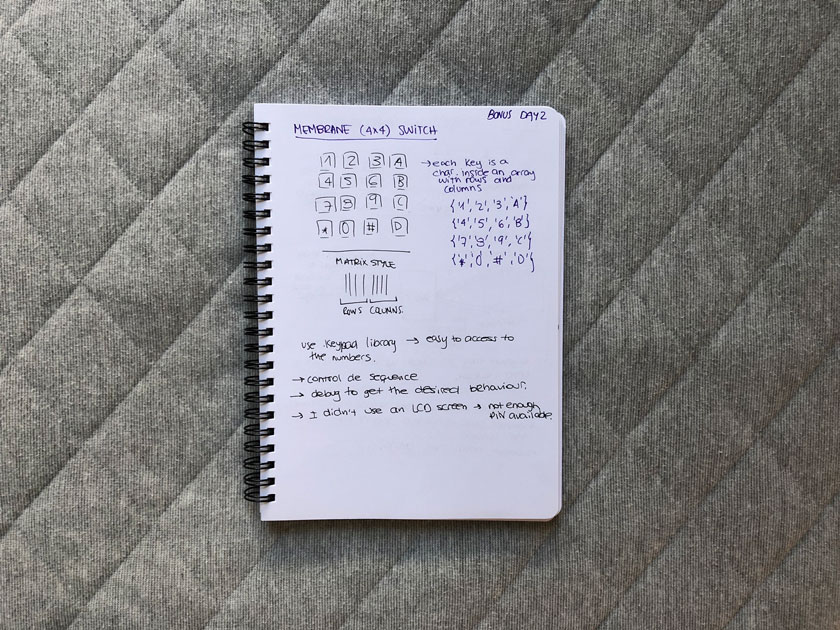
2 COLOR LED AND MEMBRANE SWITCH TEST
PROTOTYPE
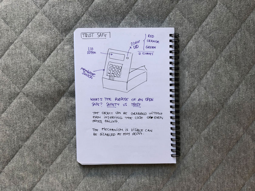
CODE
DAY 3
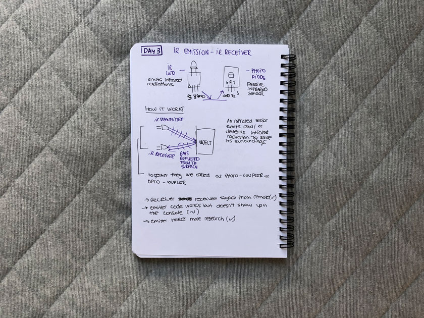
IR EMITTER & IR RECEIVER
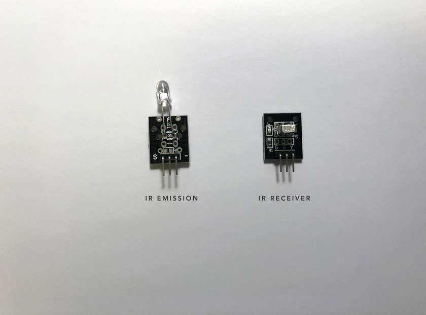
MODULES STUDY
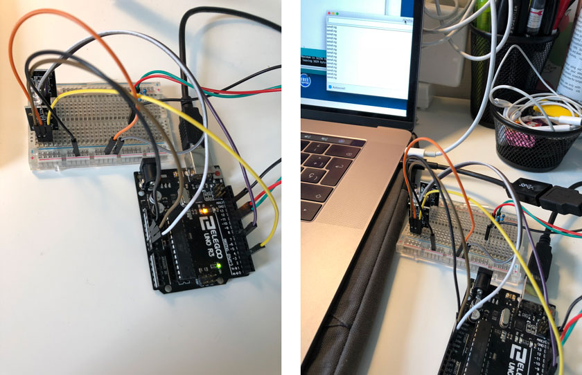
TESTING IR EMISSION + IR RECEIVER
CODE
DAY 4
BALL TILT SWITCH
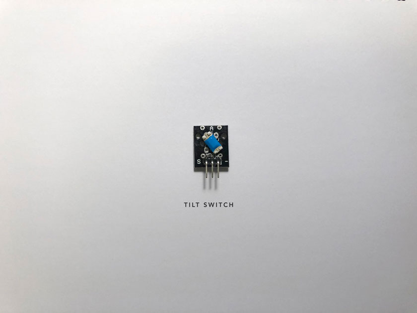
MODULES STUDY
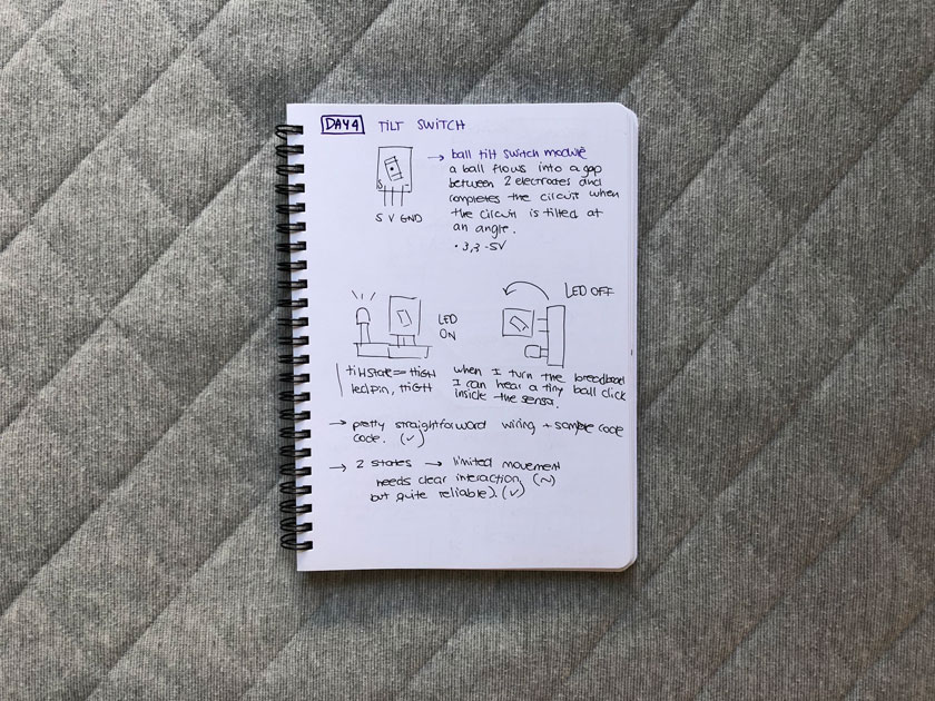
TESTING TILT SWITCH MODULE
PROTOTYPE
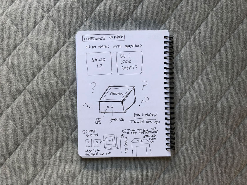
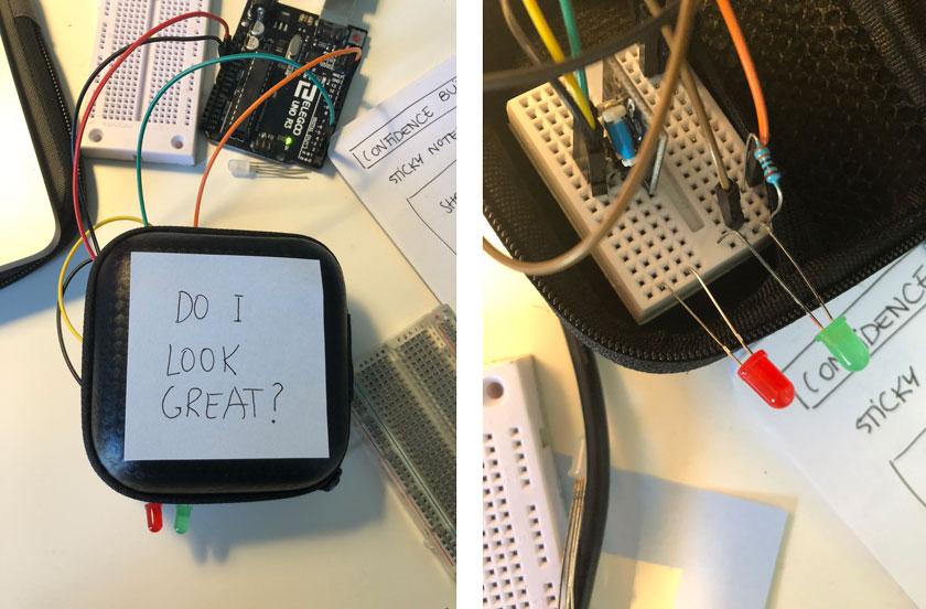
CODE
DAY 5
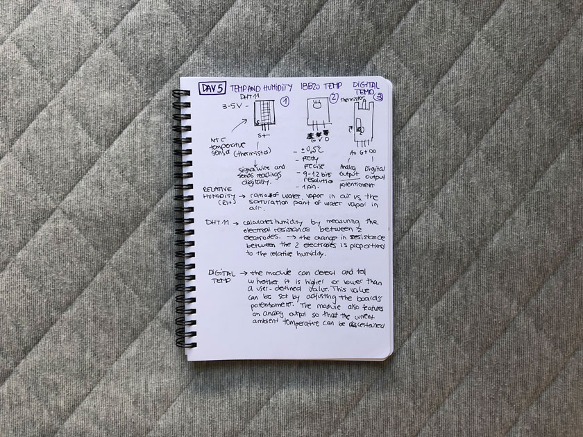
TEMPERATURE SENSORS
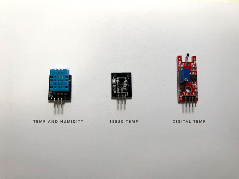
MODULES STUDY
DIGITAL TEMP SENSOR TESTING
TEMP AND HUMIDITY SENSOR TESTING
18B20 TEMP SENSOR TESTING
PROTOTYPE
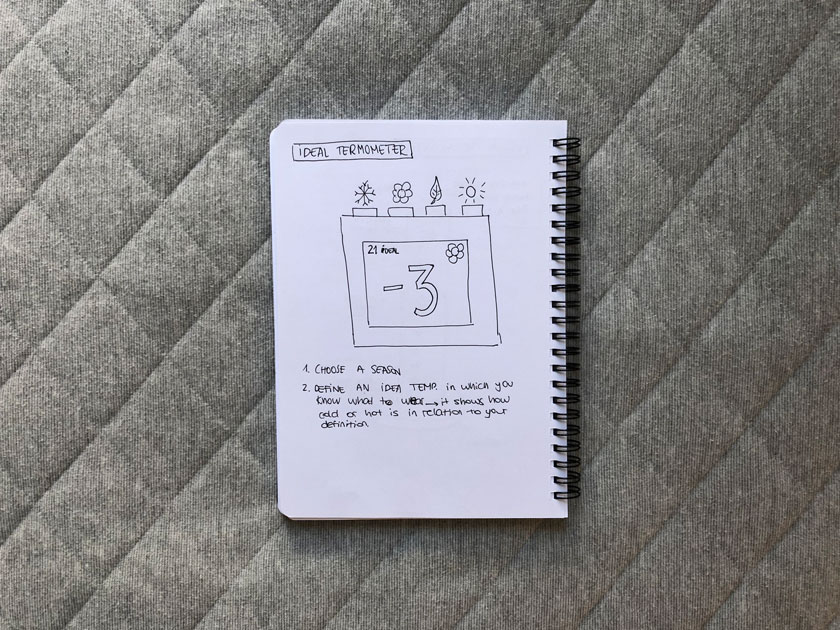
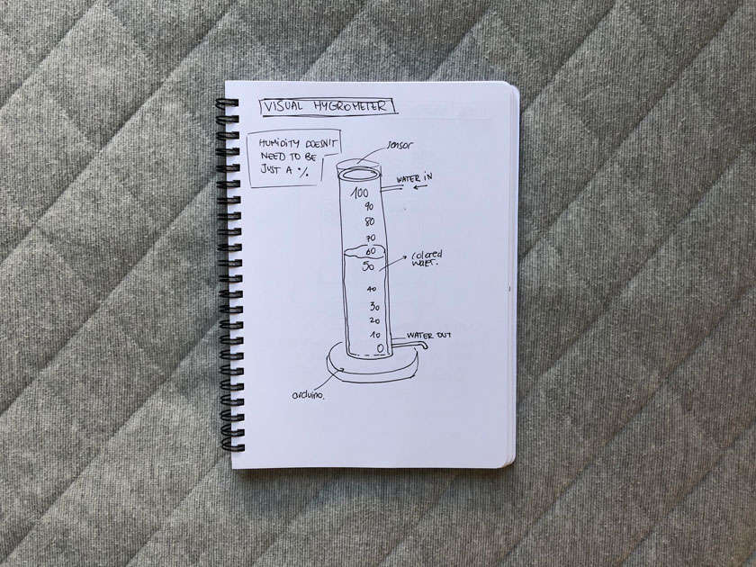
TAKEAWAY
