DESIGN PART
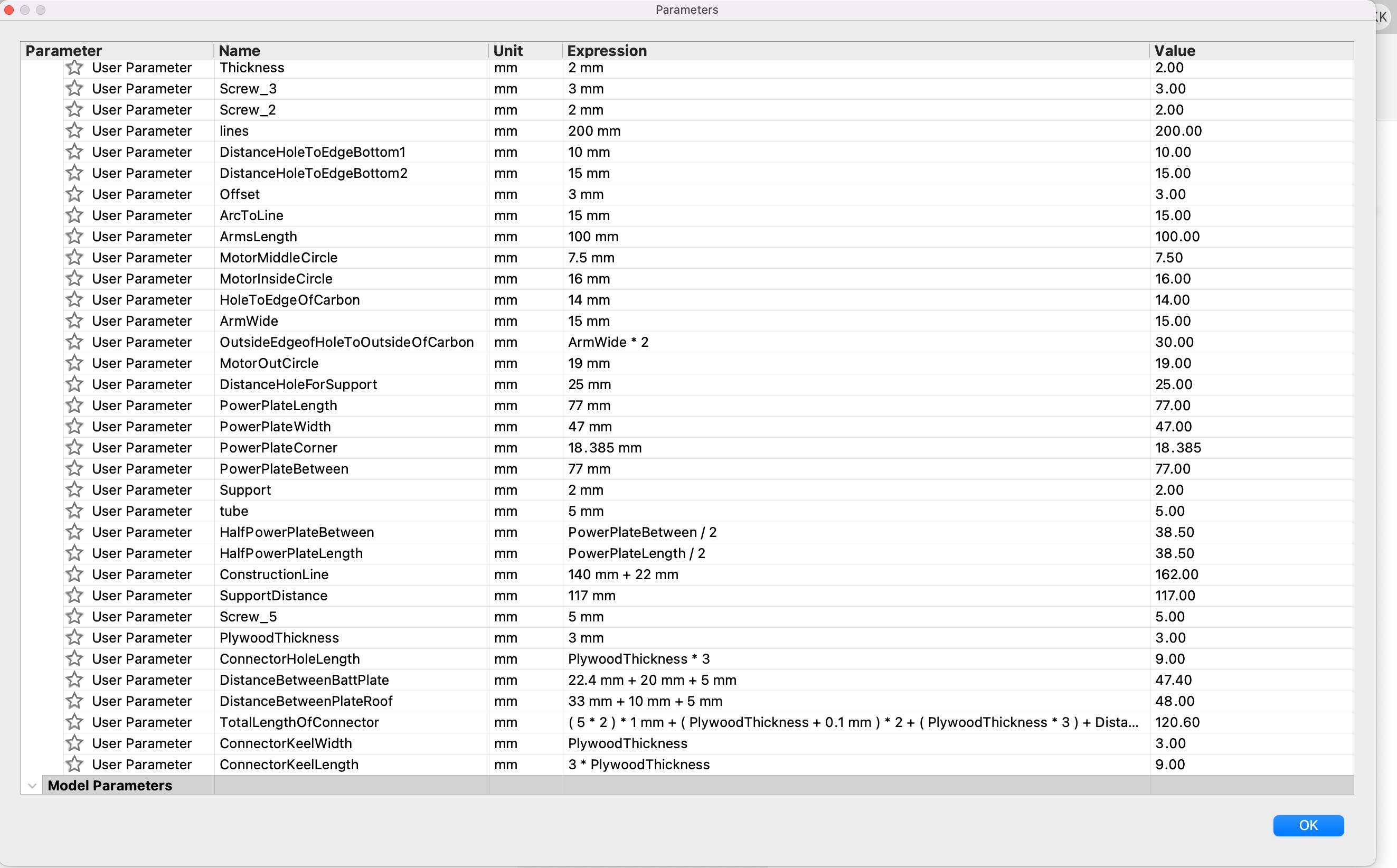
- First of all, I created the parameters, but they still changed during the design development - I deleted, corrected and added something. This was the first time when I really appreciated the importance of the construction lines - I needed it a lot.
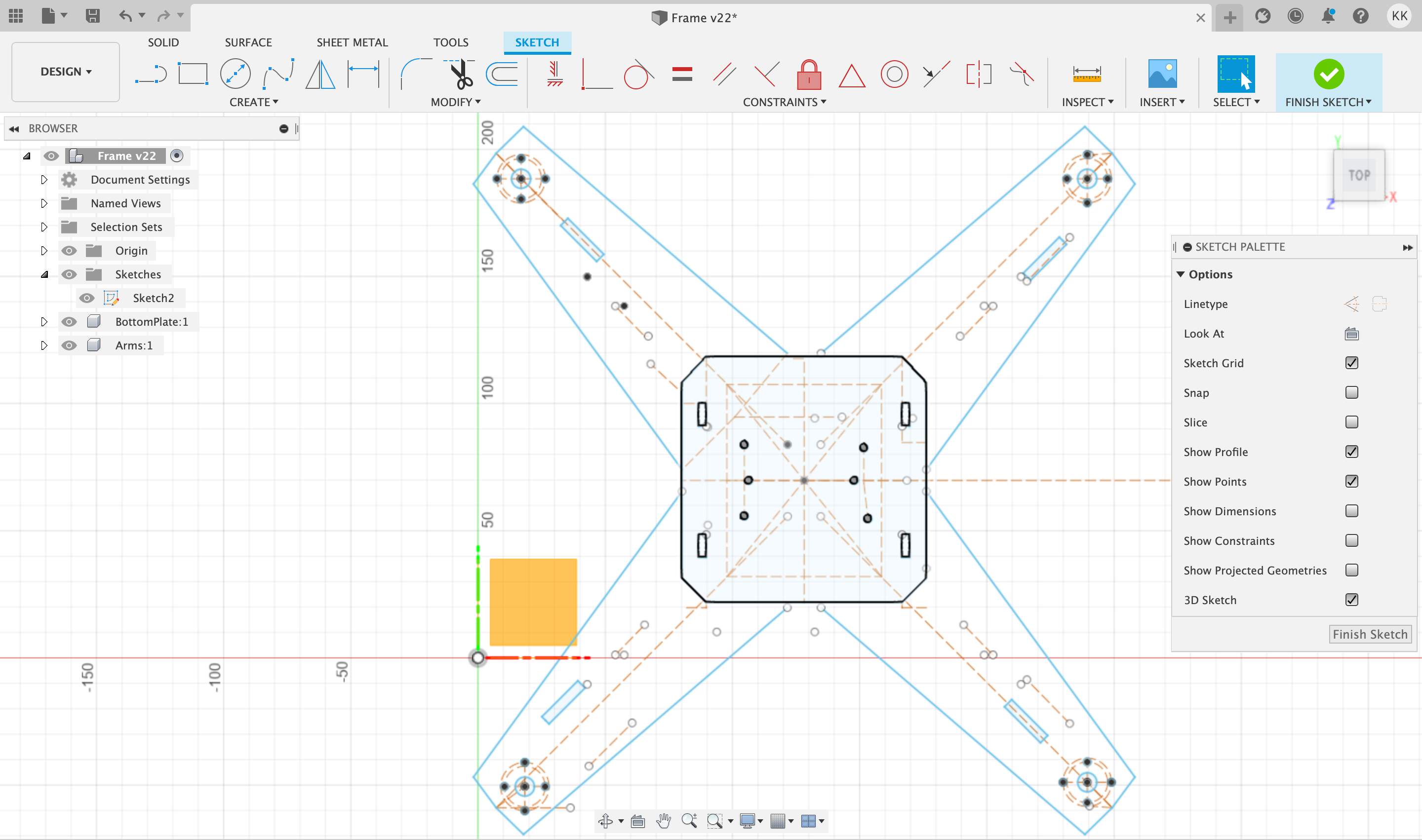
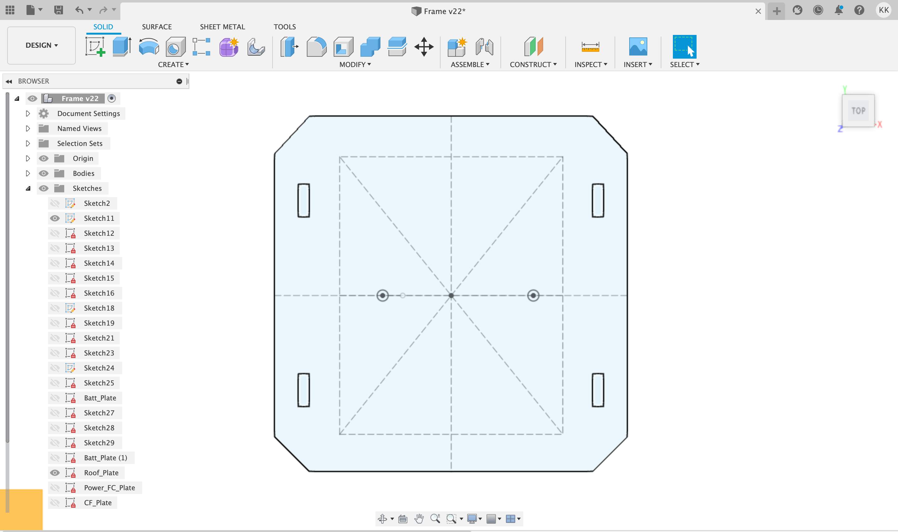
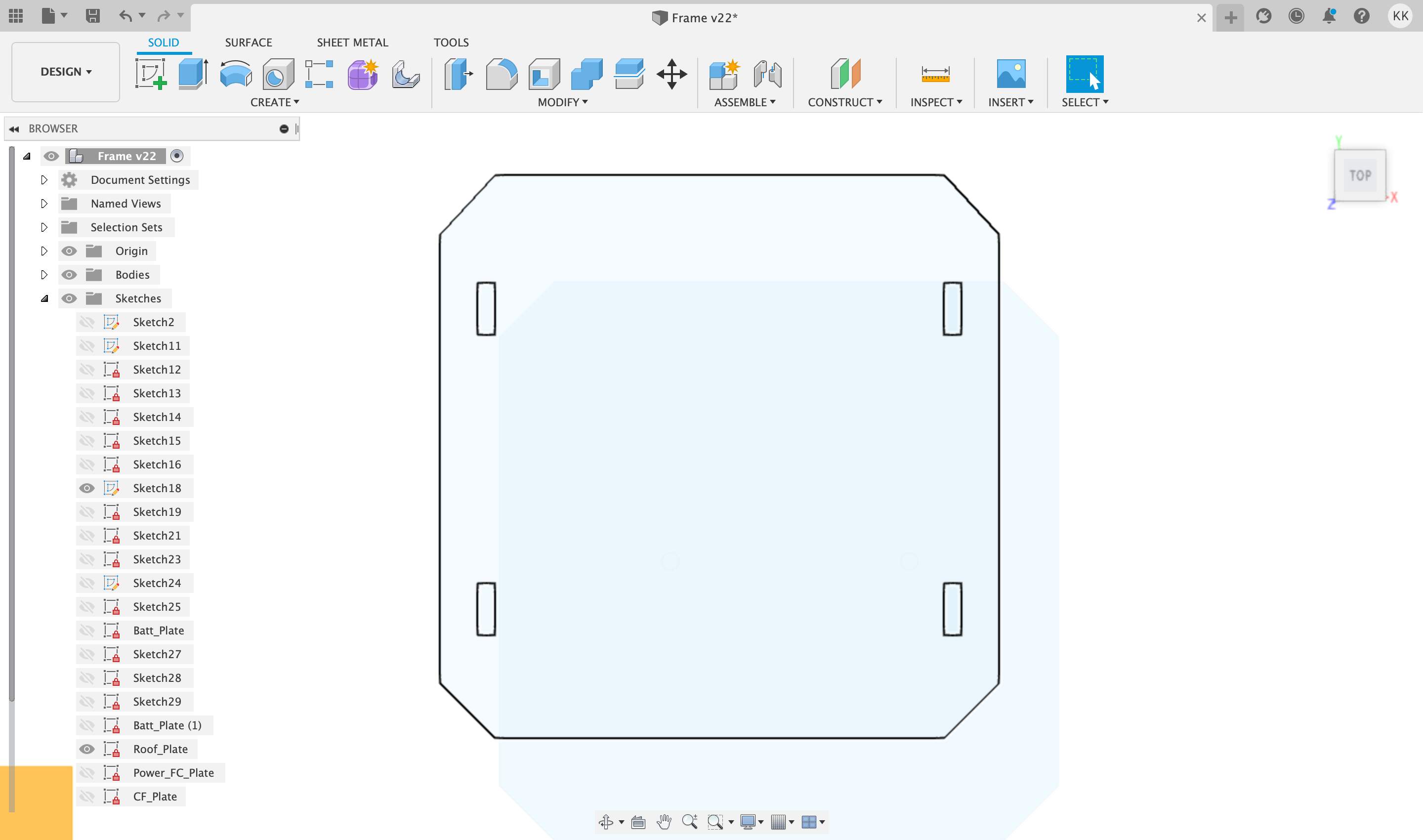
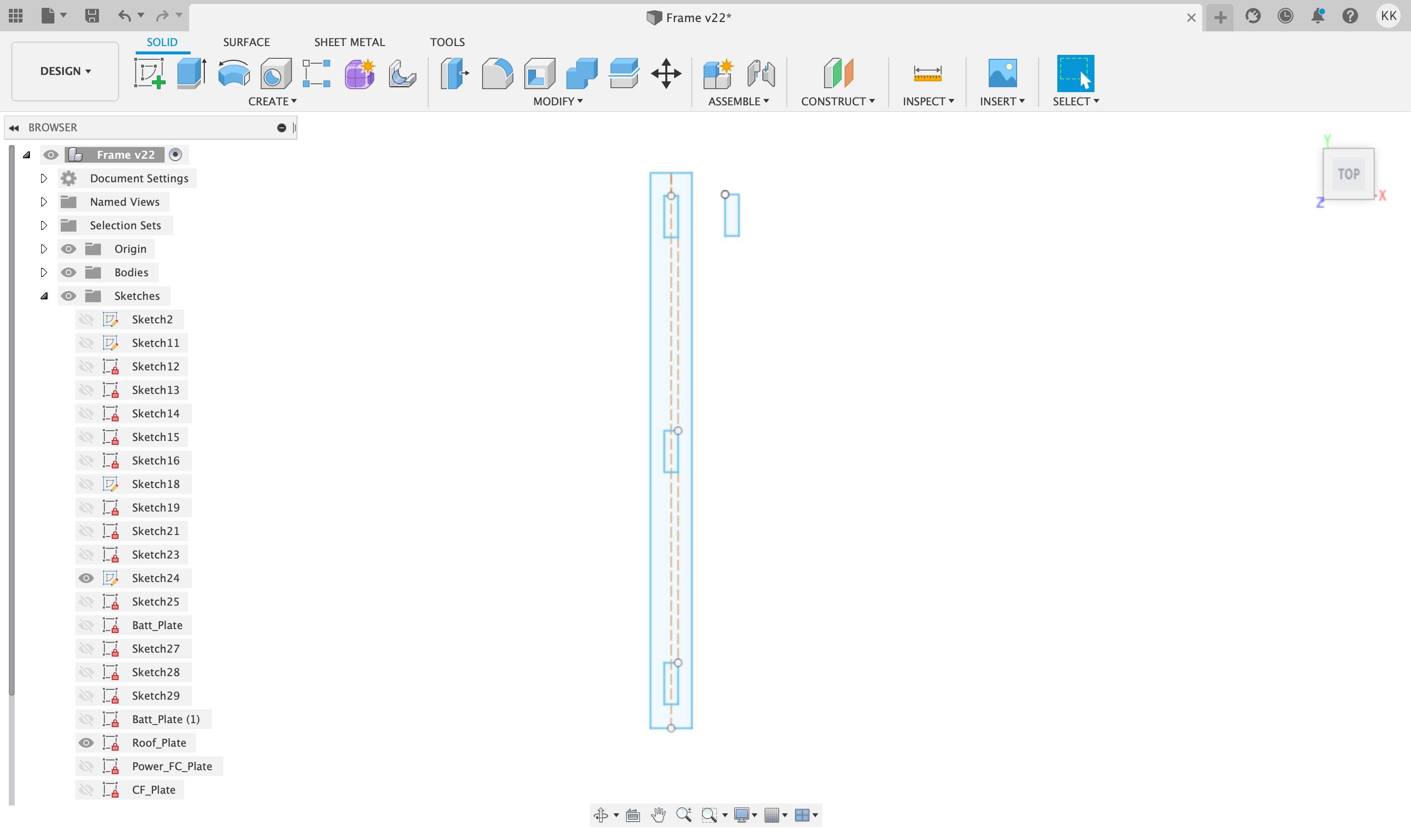
- I also used the middle of the frame to create the battery and roof compartments. To save time for the same middle part I
(a) in the case of batteries, I removed the screw locations on the flight controller PCB and added the screw locations required by the battery holder.
(b) in the case of the roof, I removed all the screw locations, leaving only the rectangles for the connecting lines on the side. - Unlike the main frame, the connecting lines will be printed in 3D PLA technology. Rectangular connection lines are supports and the distances between them are calculated - by forecasting and manually measuring in the real environment how much space the battery holder needs with the batteries, also for the safe distance from the batteries to the power supply PCB and how much space the flight controller PCB needs including accelerometer & gyroscope and receiver modules sizes. For this sketch I used the "Extrude" tool and with right-click chose "Export as .STL".
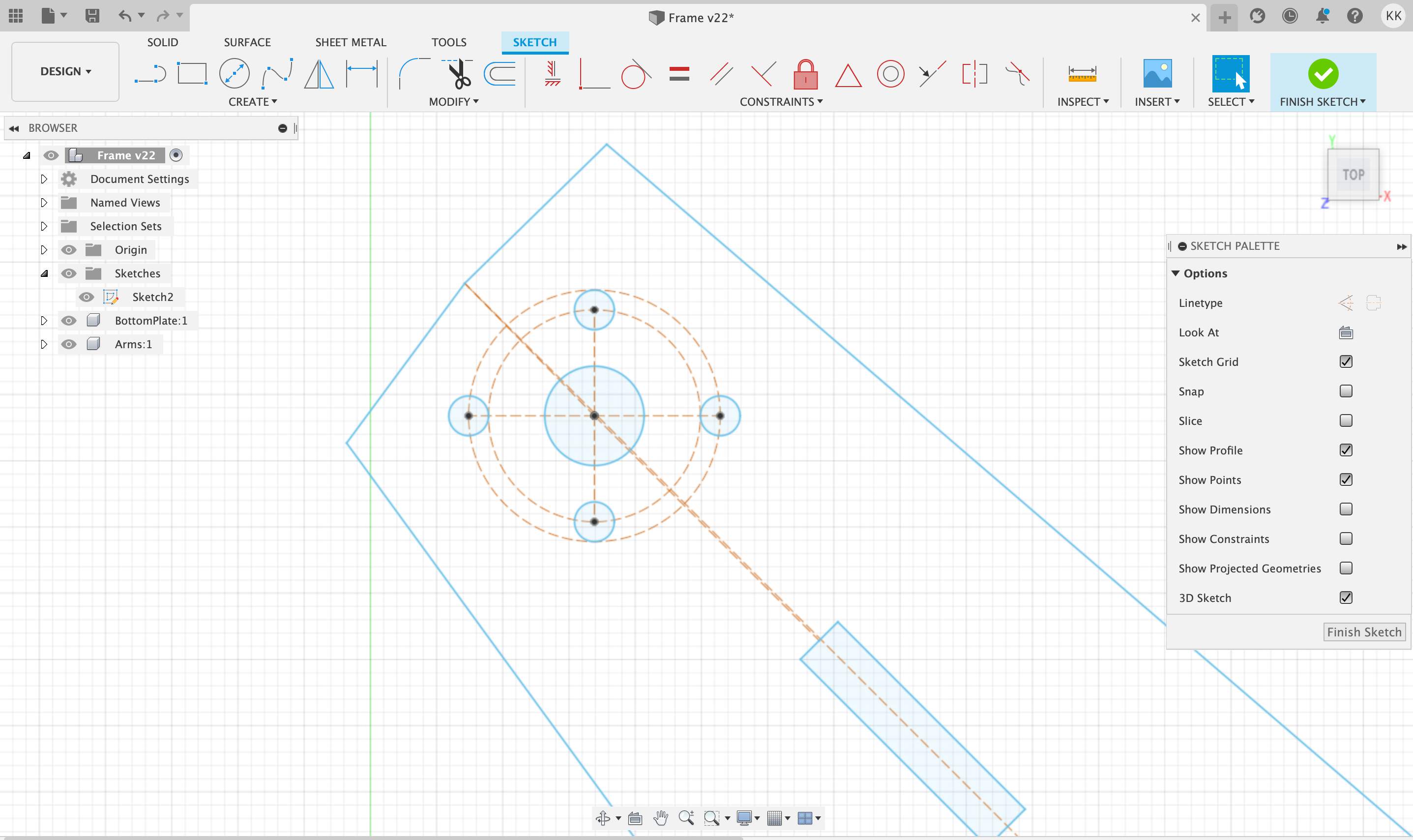
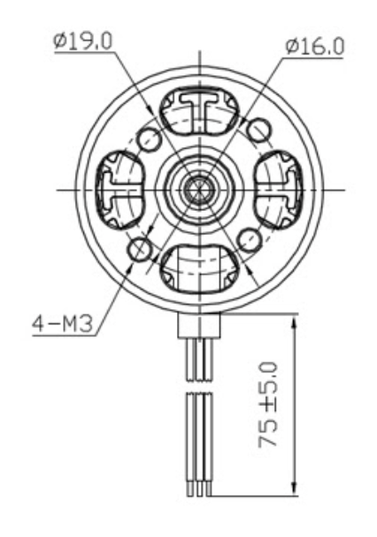
- Precisely creating screws distances for motors was a challenge! First of all, I only realized after the first attempts that the arrangement of the screws is not symmetrical. Secondly, finding the manufacturer's schematic drawing was not so easy (I hope someone will find it useful here). Third, it took me a while to figure out how to model it (geometry is always a challenge for me).
- I had trouble exporting the model to .DXF format - I don't know if it's a software bug or just my ignorance, but clicking "Finish sketch" and then right click to export it as .DXF (the format required for laser cutting) will export also all construction lines and in laser cutting, this means that the construction lines will also be lasered - this is not what I need. The only solution for me was after the sketch was finished, selected the "Extrude" tool and selected zones. After running the tool, a new "Body" is created, then I opened this "Body" as a new sketch and then I can export it as .DXF.
NOTE:
"HERO SHOT" DESIGN SCREENSHOT
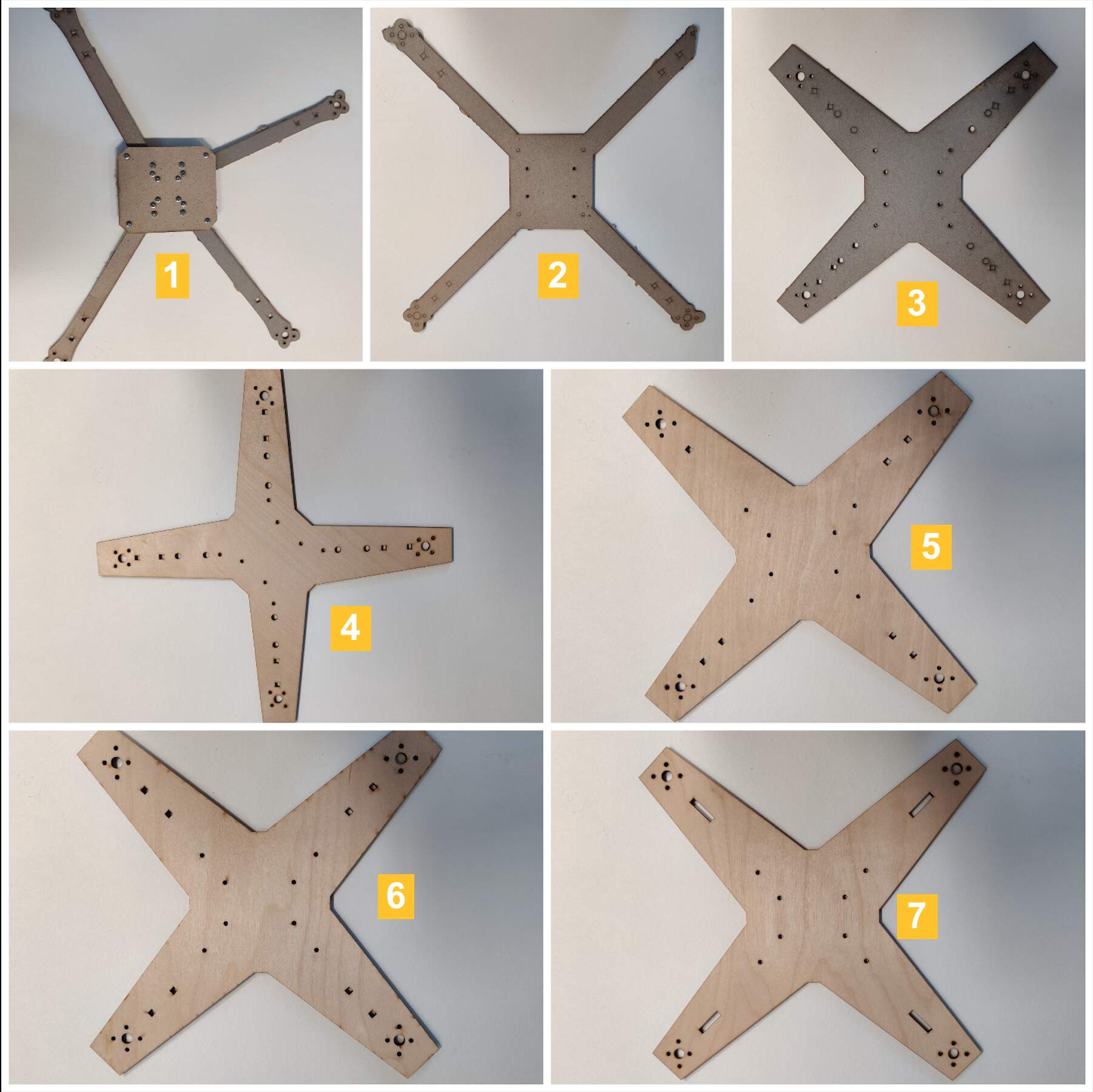
IN FRAME DESIGN DEVELOPMENT I FAILED.. FAILED .. FAILED MANY TIMES
- In the first attempt, my drone frame consisted of 16 screws and was absolutely asymmetrical and a bit even funny. The second time, after the advice of my instructor Kris, to make everything as a unit rather than from separate parts, it looked better - less screws, but still asymmetrical and wing sections too narrow. The third attempt has already begun to look like a drone with many connections (holes) places. Then it started to feel like I was nearing the end of the drone frame design and started making it from plywood. When I made it from plywood and it seemed like everything was wonderful, someone told me - hey, but your frame is asymmetrical, should it be? OHH, NO! In the fifth picture you can see that I reduced the connections, at first I thought that the ESC wires would be pulled through the back side, later I gave up this idea due to too small places. I released the new version and OH, NO - in the Fusion software extrude function I forgot to mark one landing gears connection. The sixth image seemed like a final version, but then in parallel developing landing supports design with other types of connections - so each change in a other part also requires a change in the frame design. The seventh is the final version!
CUTTING WITH CARBON FIBER
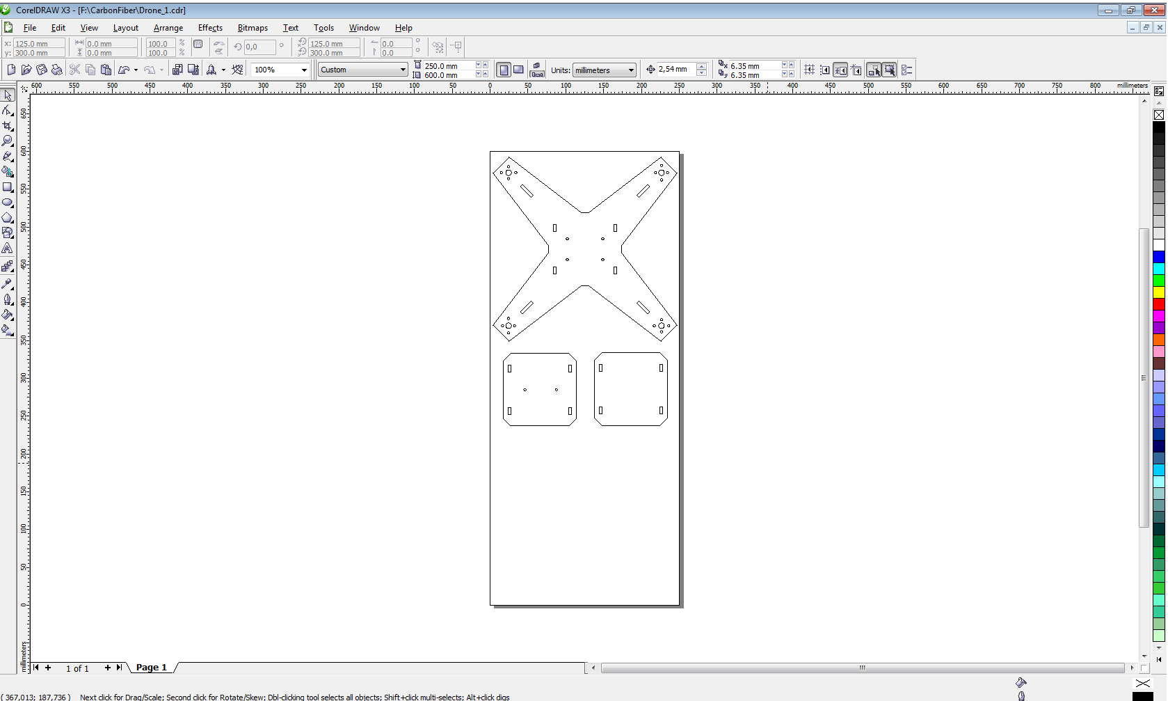
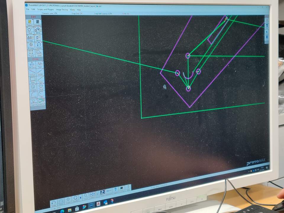
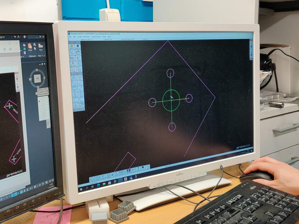
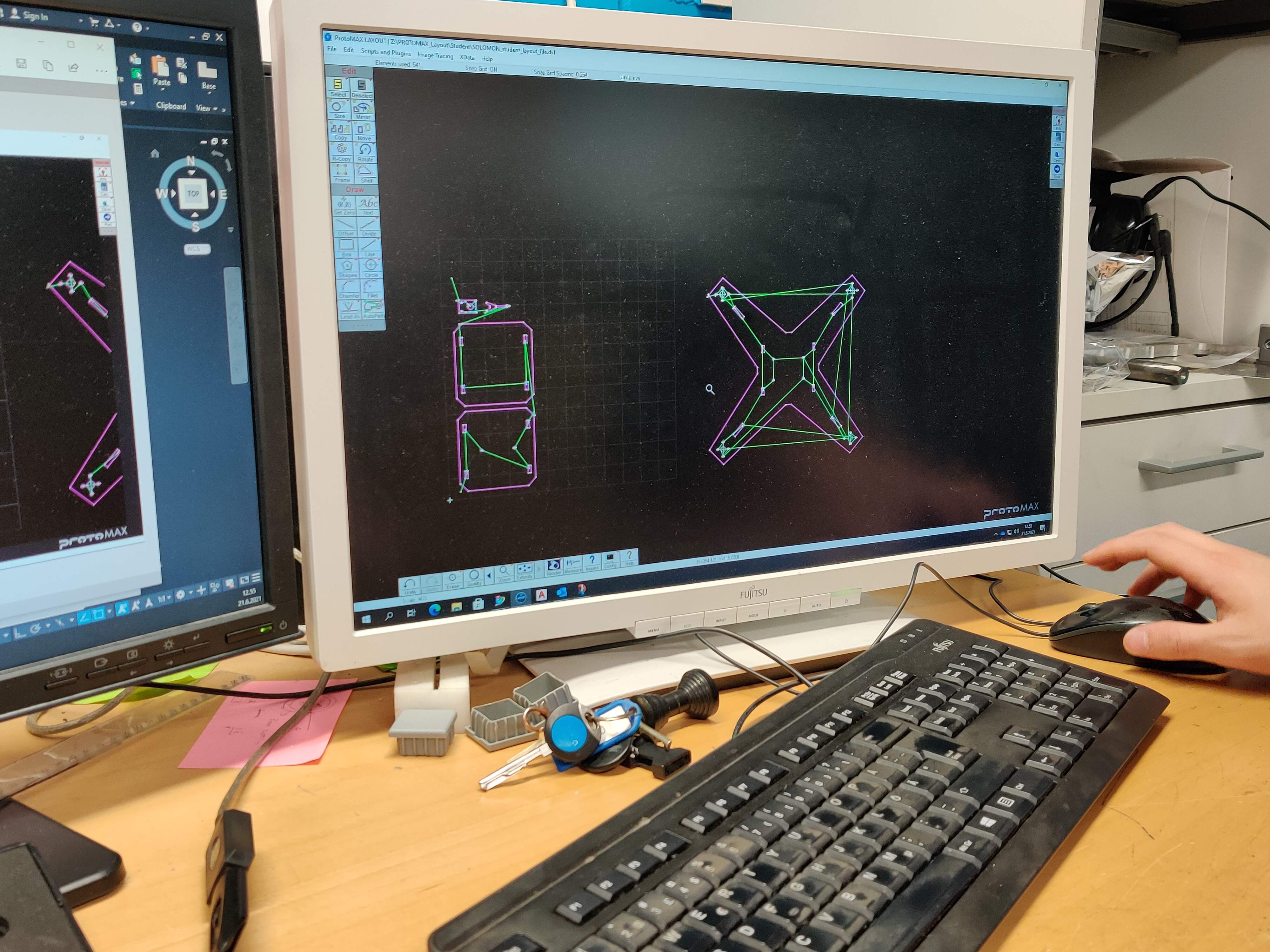
- While preparing the file in the ProtoMAX software, when the cutting path was generated, I noticed that something looked wrong. Zooming in on the design revealed errors when exporting .DXF - elsewhere the design is missing elements (unfinished circle), elsewhere some unnecessary lines are hidden under circle, which the machine would have cut out. This is probably due to the export from Fusion 360 and the fact that a duplicate of sketch 2 was created in sketch 1. To prevent this, the inner circles were redrawn in the software manually.
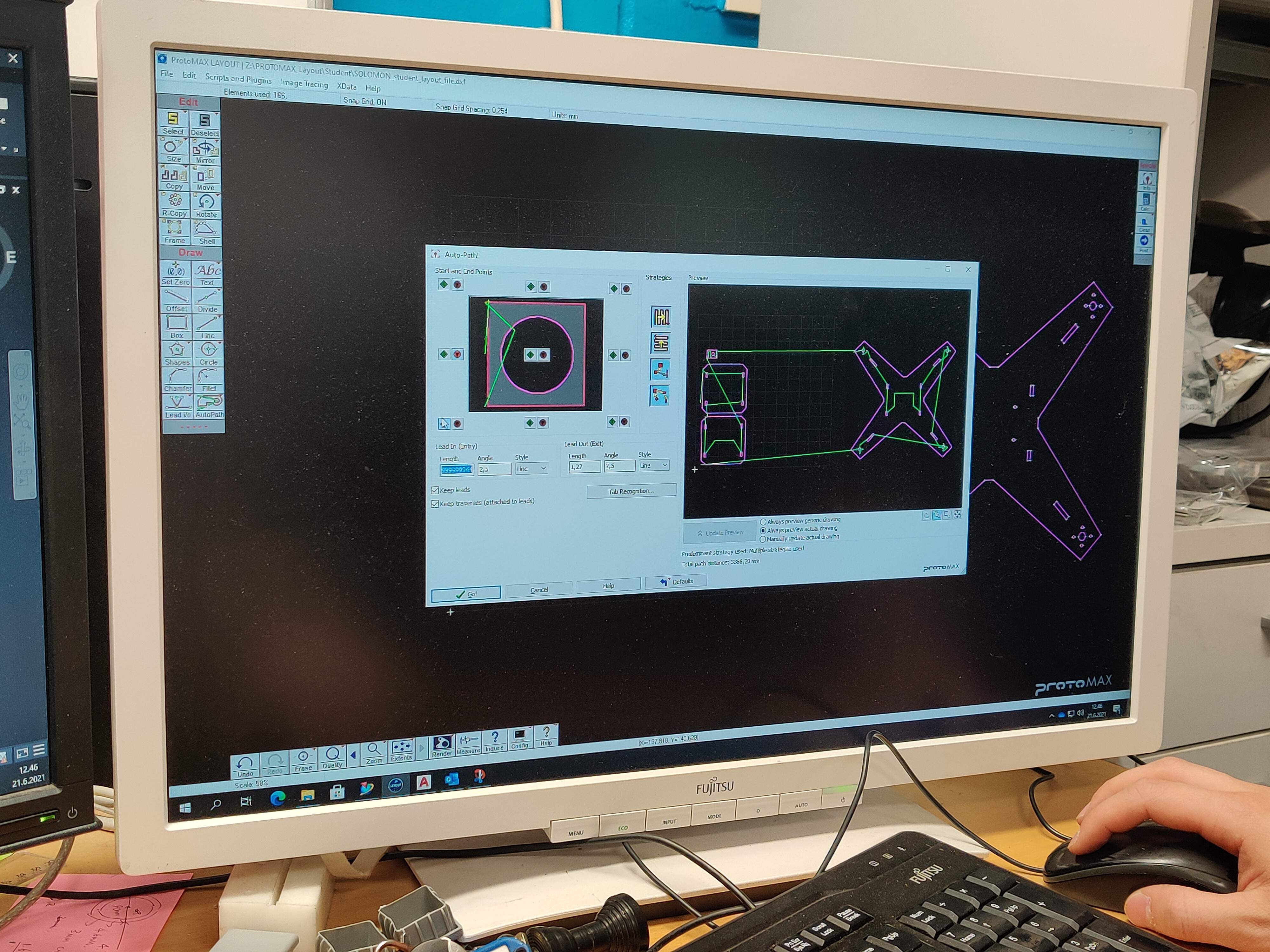
- When it was corrected using the AutoPath (Advanced & Configure) tool, a path was generated. The starting point outside the cutting model itself is marked. The resulting of cutting paths are shown in green color.
- The material sheet was then loaded and locked. Then the position of the Z-axis was then determined with a special tool.
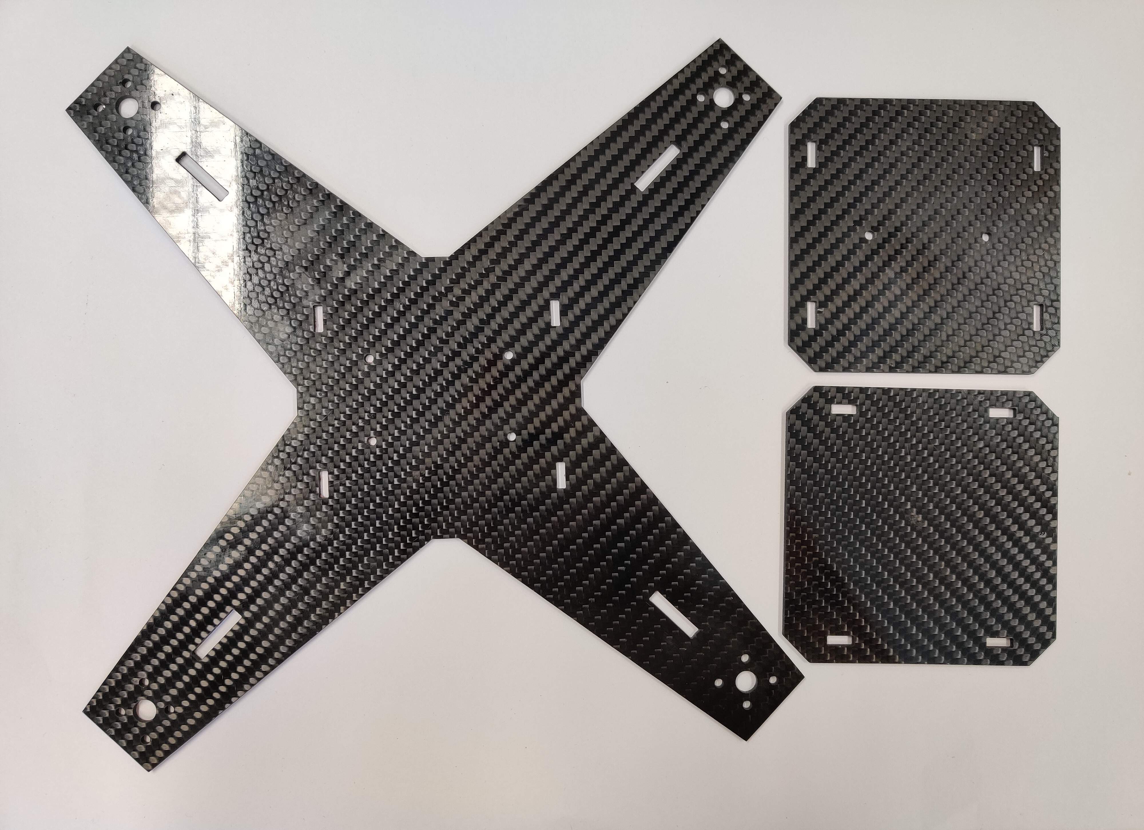
- Then in the ProtoMAX MAKE software we chose the material, material thickness and defined tool Offset as 0.327 mm. The process is not visible to the eye during jet operation, so the only option is to rely on the real time display - there you can see how cursor moves through the toolpaths. My frame was cut out in 7 minutes. The other details even faster, did not take time, but about 3 minutes.
RESULT OF WATERJET MACHINE
3D PLA TECHNOLOGY PRINTING ISSUE
- In order to prevent the screws from coming into direct contact with the PCB, especially with the power supply PCB, I also created 3D pipes of different sizes
(depending on the location in the drone) for the screws. I experimented several times because I had specified the diameter of the screws (3mm),
but I couldn't screw it in completely - it was related to the screw threads. Later, when I had found out the most suitable sizes as a result of experiments -
the 3D printer let me down! Several times during the printing process, it moved the model out of place. I tried to fix it
(a) apply a little glue;
(b) heating the head at a higher temperature;
(c) removed and reinserted the filament;
(d) finally leveled the build plate.
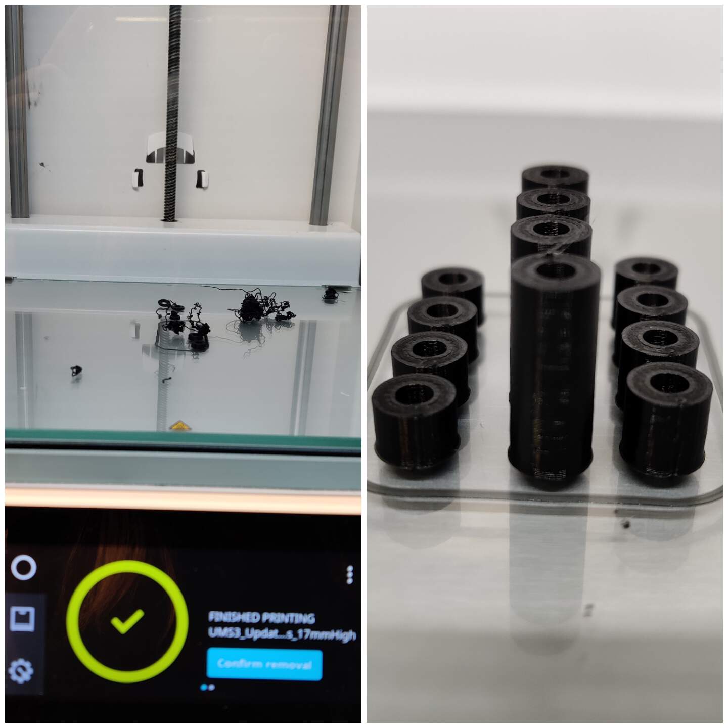
Nothing worked (what you see in the picture above as a result is still when I experimented. Something happened to my last - final version), so to avoid wasting more time - I printed it with a Lulzbot Mini 3D printer. Let me remind you that my conclusion of 3D scanning & printing week for this printer was not positive, but I tried. And succeeded! The quality is lower, but it will not annoy with the operation of the drone.