3D SCANNING WITH ARTEC EVA
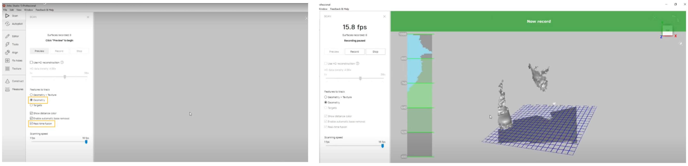
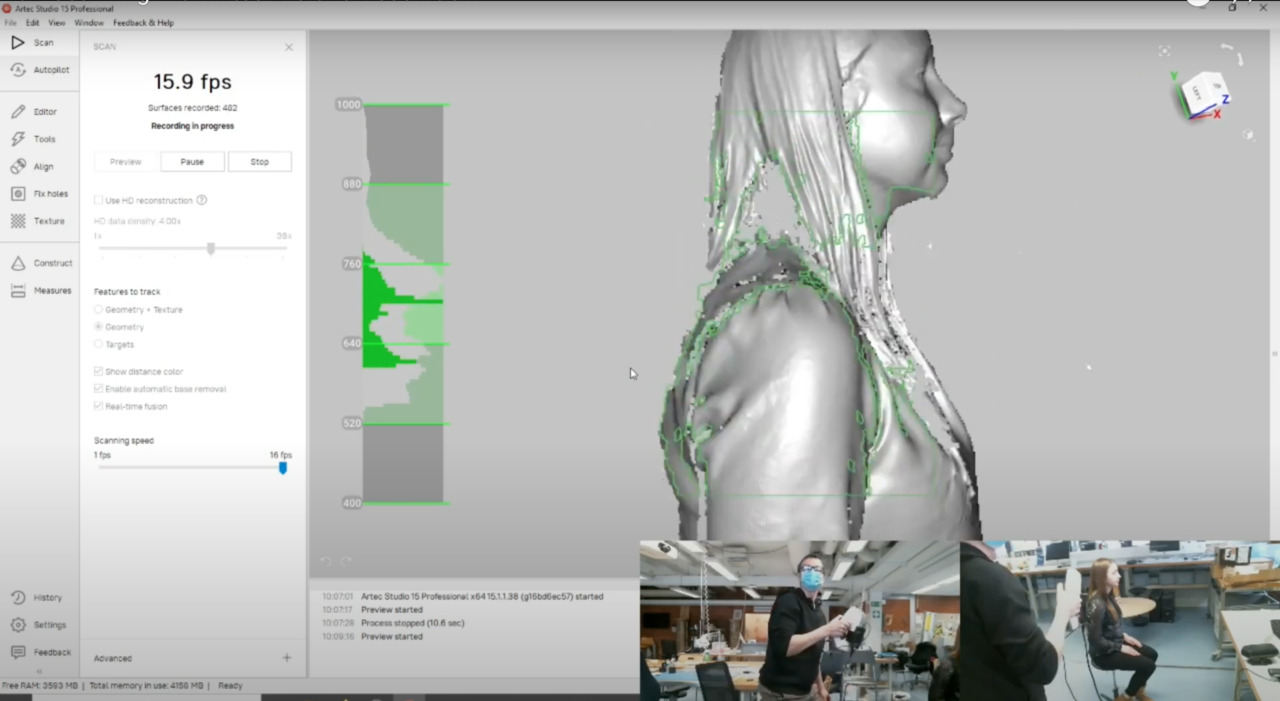
- First of all open software Artec Studio 15 Professional. In order to start scanning you have to press the scan button. When you see the green button on the scanner that means it's ready. You can activate preview mode by pressing the play button on the scanner or the preview button on the user interface. Before you start scanning it makes sense to check settings. If you want capture the texture of the object then you should select the geometry and texture option, but in this case as I want to 3D print it, I need to select the geometry option only. Enable also Real-time fusion option it's going to make it a much cleaner scan. After that press the preview button on the sensor, some seconds to initialize the sensor and the first thing that you need to do is point the camera so the sensor towards the object that you want to scan. You need to find a ground plane and once the ground plane is found then the sensor and the software is going indicate it with blue grid. When you see that you can start scanning by pressing the play button or the record button on the interface. Me scan my instructor Kris. But I also could tried my hand in scanning, because I scan student Russian.
- Now carefully and slowly move upwards to approximately the area that you want to capture as a scan, after that model (in this case - me) start spin around very slowly. When you feel that it is enough, you can stop by pressing the stop button.
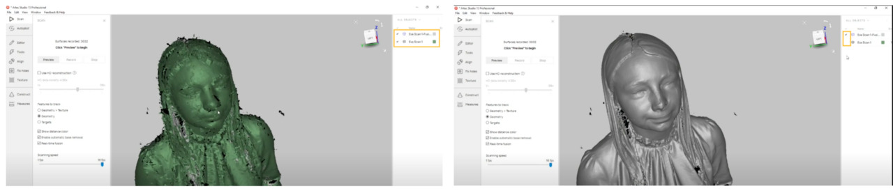
- It looks a little bit noisy, but that's because actually I have two objects scanned, one is the original scan and the real-time fusion part. So, you need hide the original scan and show the real-time fusion.
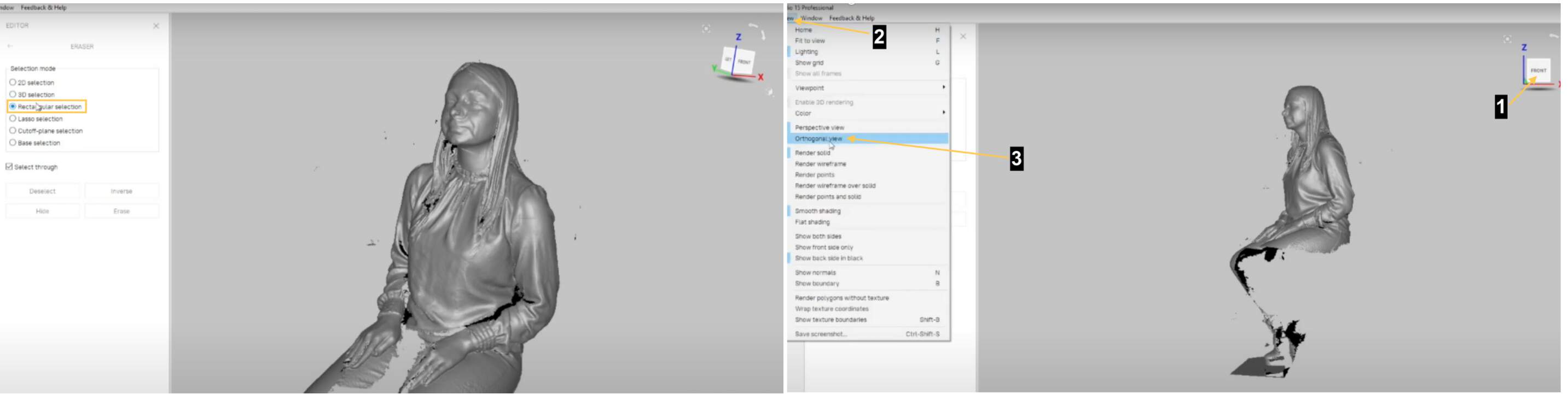
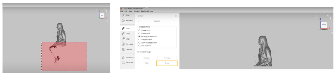
- Software have a lot of tools. For example, erase all things that I don't need for printing. In Eraser section I choose Rectangular selection for the selection mode. Then rotate to look from side (front) and enable the orthogonal view.
- I want delete everything that is below approximately elbows level. To do that - hit and hold CTRL on the keyboard and drag with the mouse area what I want delete.
- Now, if I rotate object I can see a lot of holes (black areas), which I need fix in next steps. Go to section Tools. First I want to get rid of smaller objects over, for that open Small object filter settings and there I specify what is the polygon count and press Apply. Next I want to fill the holes, for that I press Hole filling button. After that smaller holes are being filled. Also I apply Mesh simplify and Smoothing, but difference isn't so visible.
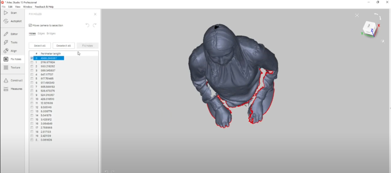
- For fix big holes I go to Fix holes section and fix all holes which I can see in dialog box.
- Not a big changes can see, but I also apply Fast mesh simplification.
- After that Export - Meshes and save it in .STL format.
3D PRINTING WITH ULTIMAKER S3
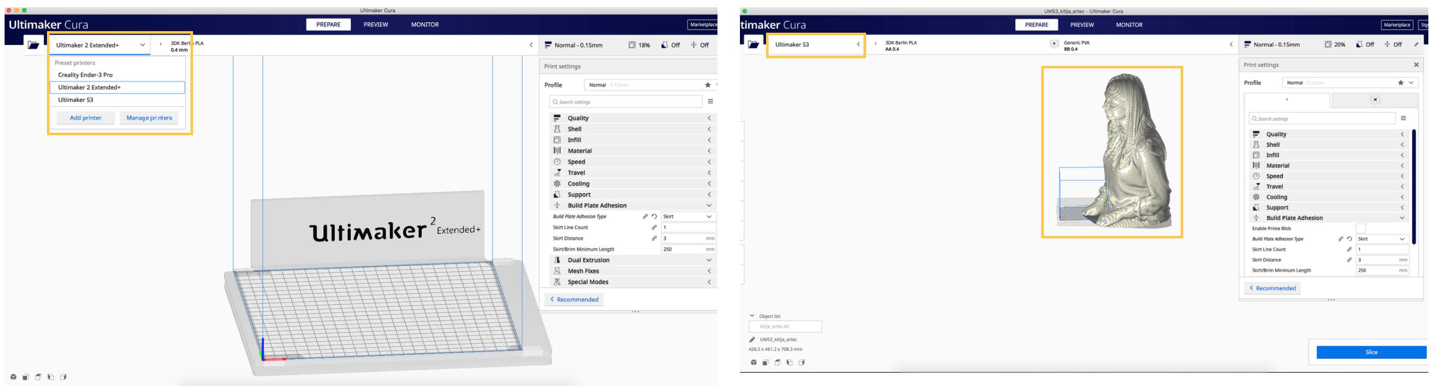
- I work with 3D printer "Ultimaker S3" which has a double nozzle system and Ultimaker Cura software. First of all I select right printer and import my scanned file.
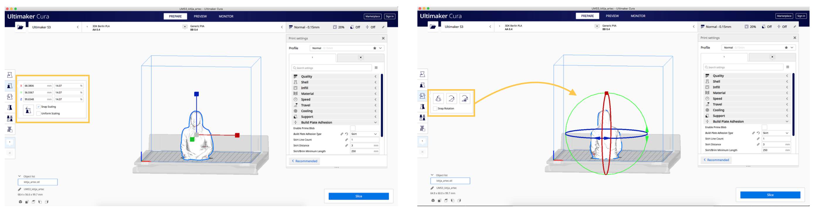
- As my imported file is too big, I resize and rotate it, because I want to see my face when I print it, ha! To resize setting I will return, because size is what determines how long would be a printing time.
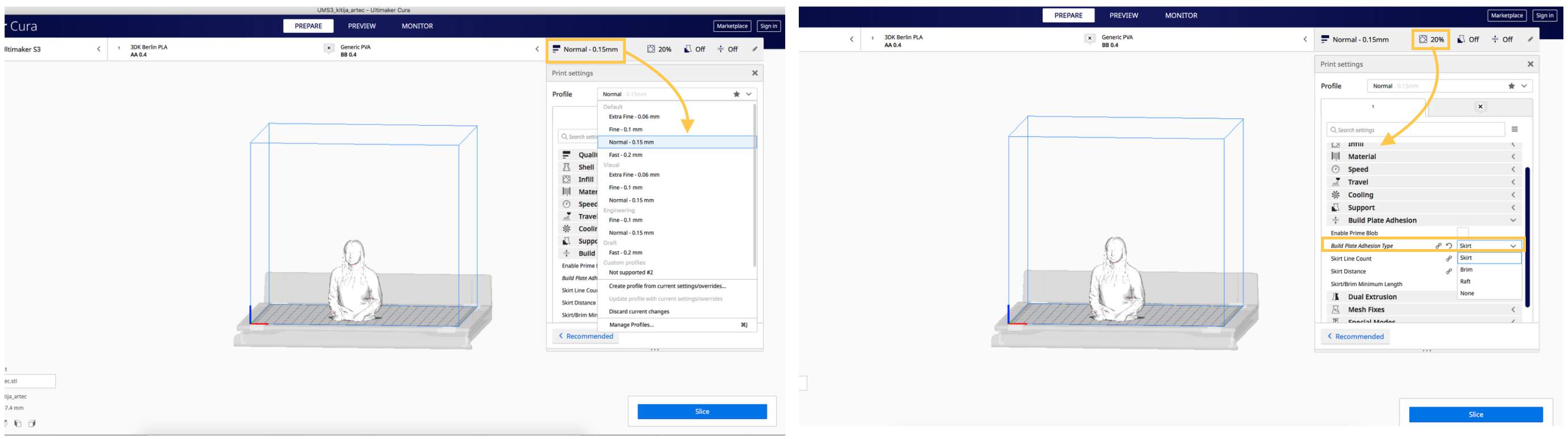
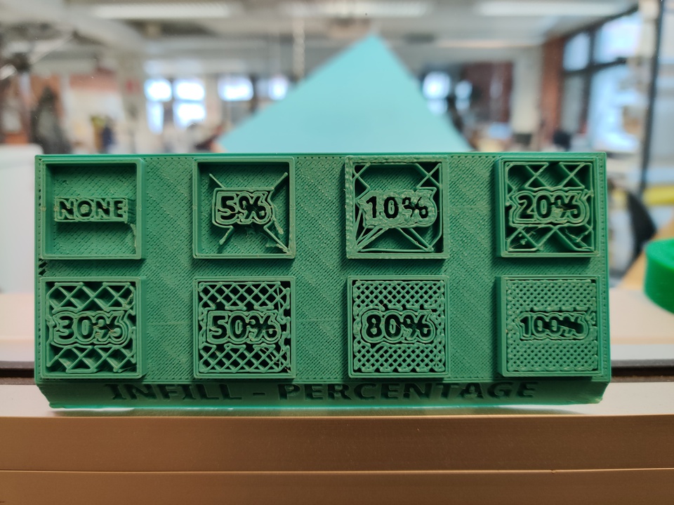
- To profile I select Normal 0.15 mm, it would be OK for body printing. About infill settings - it specifies how much material you want to have in all areas inside. (see picture below). I would try for body choose 20%. And for Build Plate Adhesion Type I select skirt. A skirt is an outline surrounding the part to be printed.
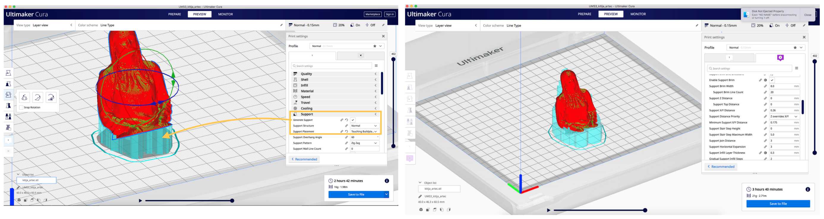
- As I want to print something with overhang I need to use support. Really cool thing is that you just need click generate support and software do it. For Support Placement I choose Touching Buildplate. Others settings I don't changed. As I use Ultimaker S3 it would be weird if I didn't use all its features - I tried my body print with one color, but support in other. I click on the support part and select that would be second printing part and then I can add color. In order to see how it's going to work in the 3D printer you can do a simulation. For that you should slice it. In order to slice it just press "Slice" button.
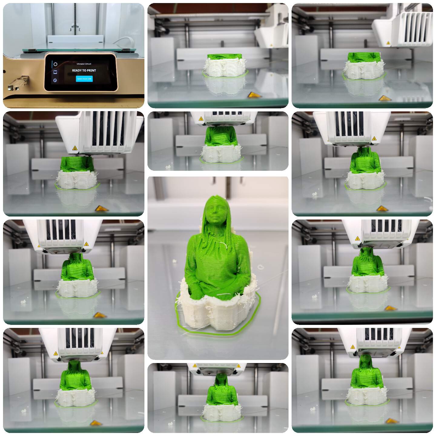
PROCESS & RESULT
3D PRINTING WITH FORMLABS
- My inspiration - Thingiverse "Human Skeleton" (by glendonwaldner).
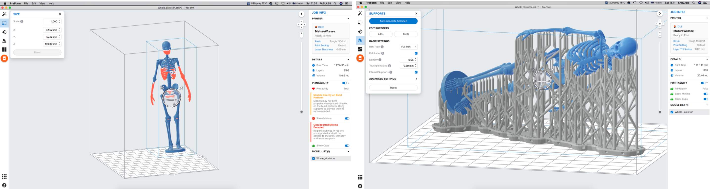
- First of all - choose the right printer. Aalto FabLab have two FormLabs printers and when I open software PreForm, I choose the printer. After that Import .STL file. When I import file I saw that it would be print more than 27 hours, whooa! - I need something to do for reduce time.
- Resize scale, x, y and z. You can see that some skeleton parts are red, it's because software alerts me that I need to use supports.
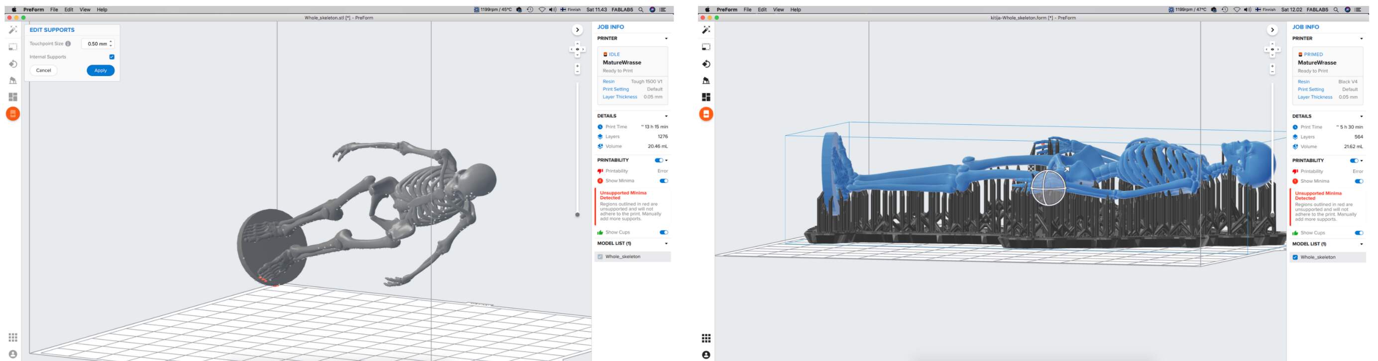
- I click on the Supports section and press the Auto-Generate Selected button. Density - 0.95 and Touchpoint Size - 0.45 mm. Now time for print is less, but still too much (more than 13 hours).
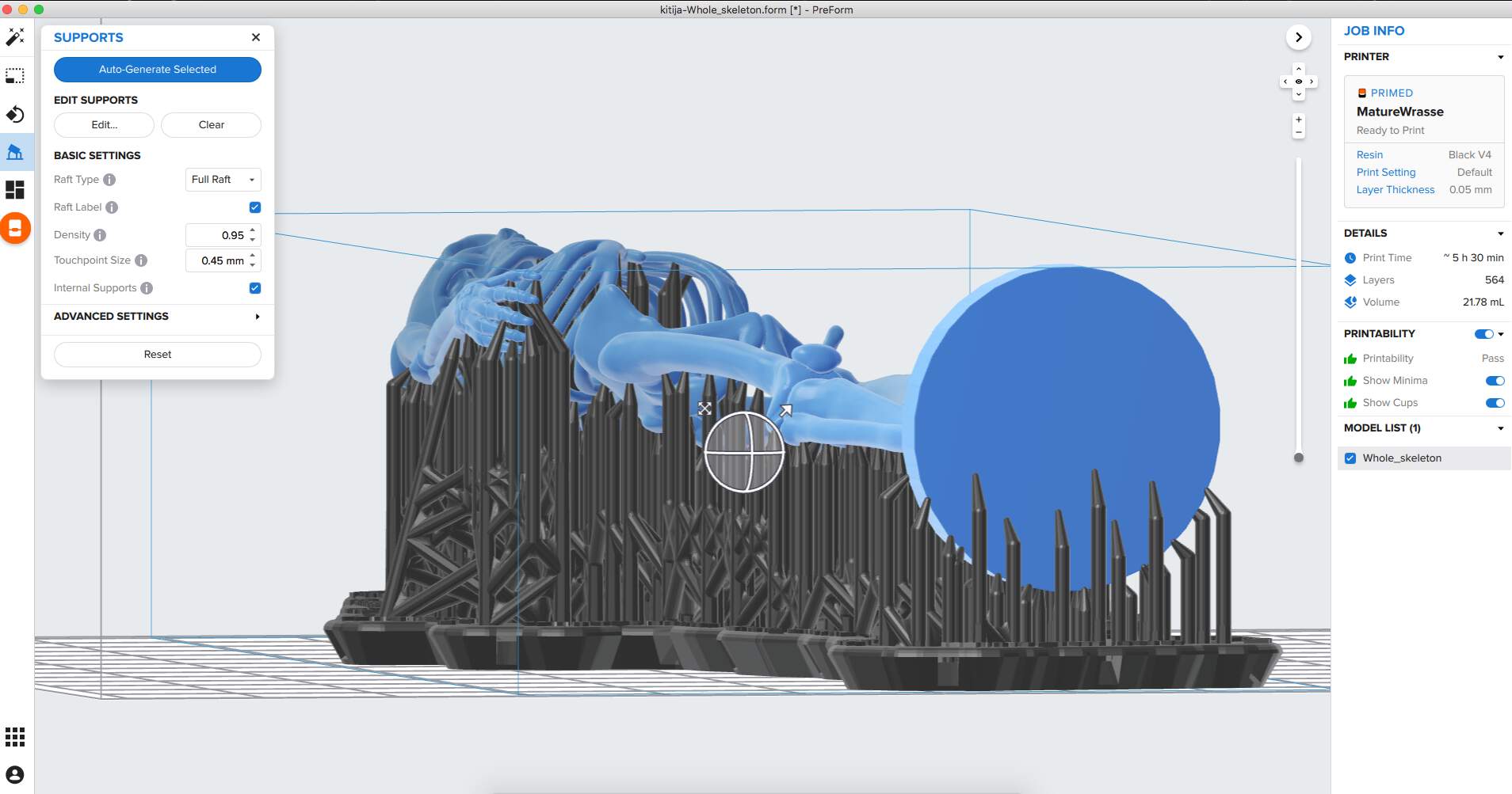
- The discovery - with object's rotation can very good manage time. I found the optimal time (5 hours), but if I want to realize it, I need add some supports points manual. After that I saw that software says that Printability - pass.
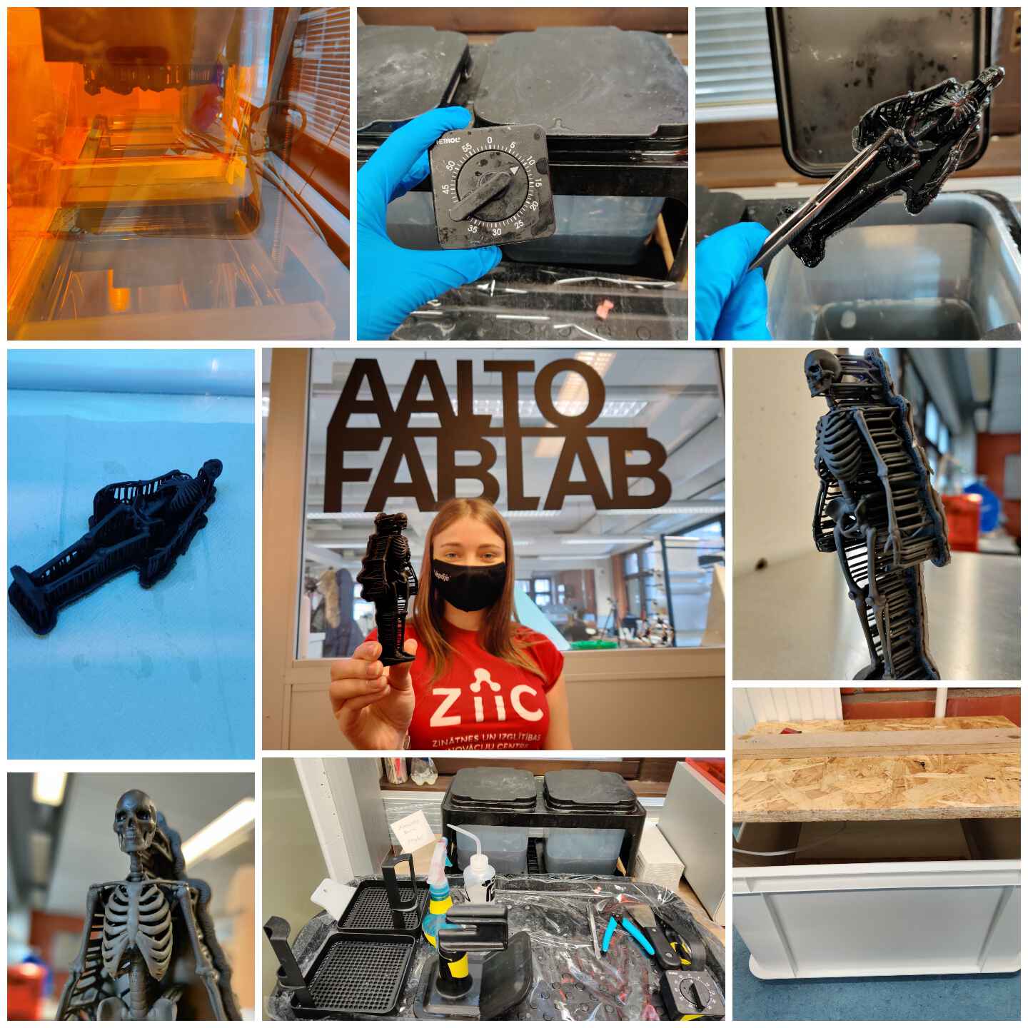
PROCESS & RESULT
HARDEST PART - MODELING SOMETHING RELATED WITH FINAL PROJECT
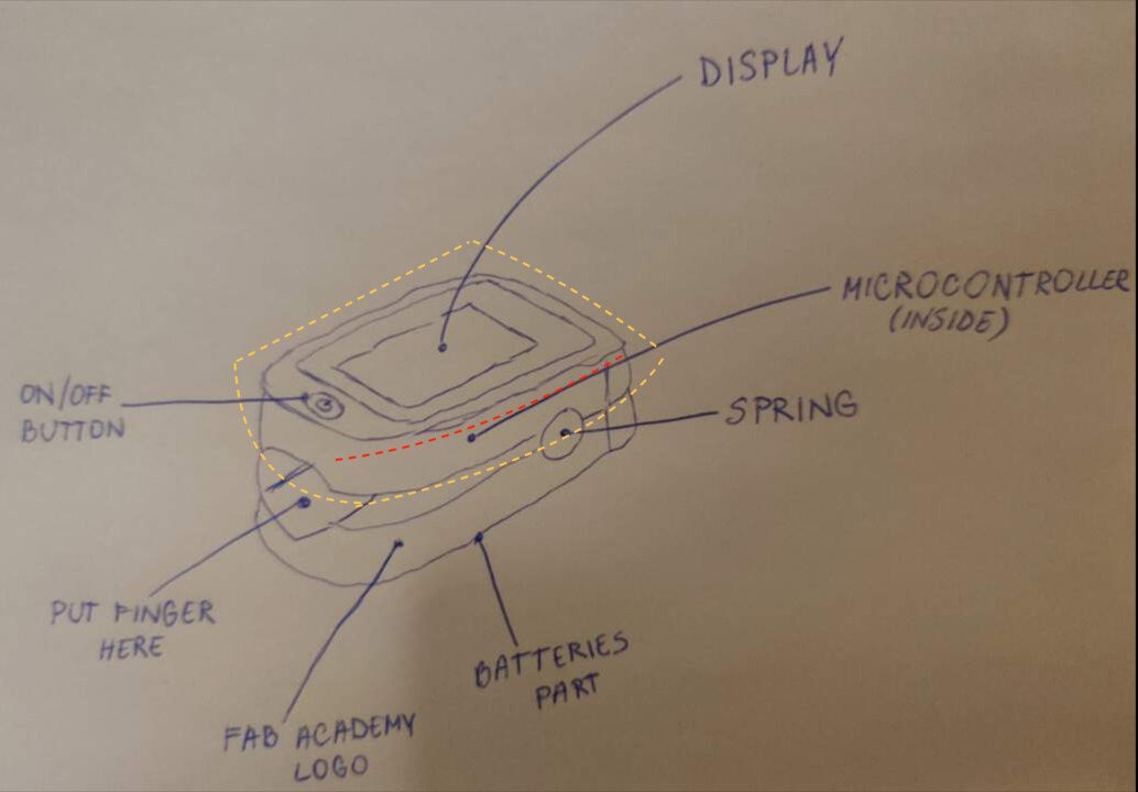
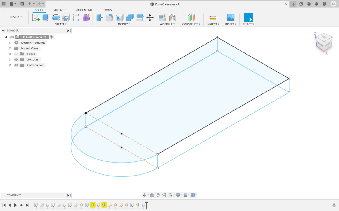
- I try to modeling what is related with my final project. I start with upper body (see below picture - dashed yellow lines). The red line divides the body into two parts.
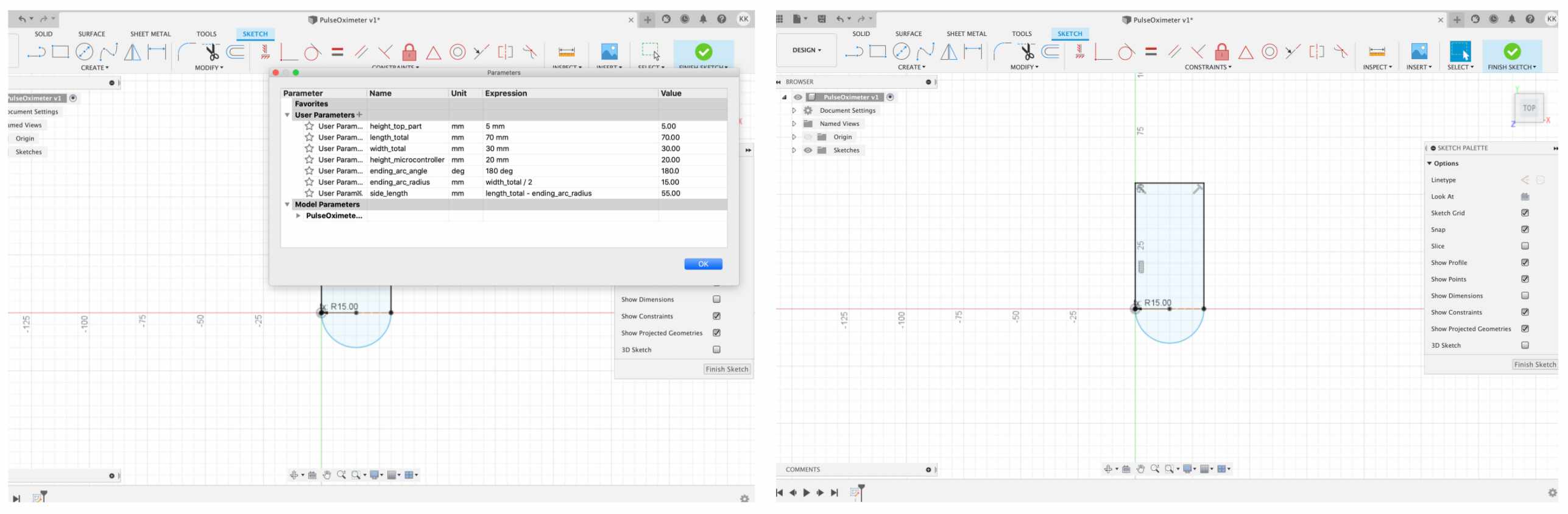
- I define parameters what could be useful and draw lines in TOP view.
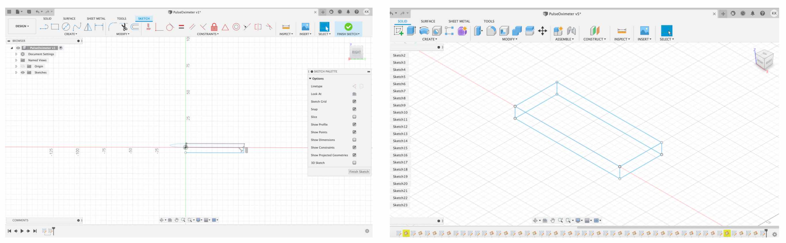
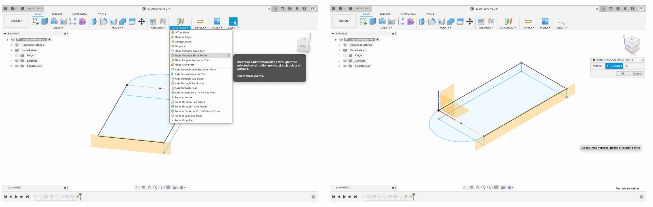
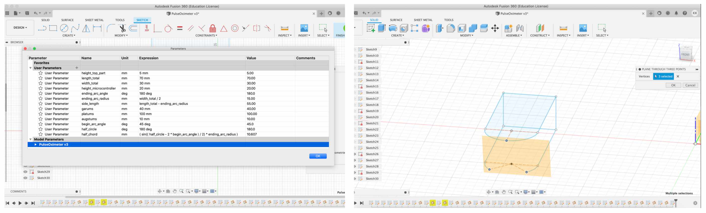
- And then I faced a challenge - I don't understand well how to work with geometric planes. I lack spatial thinking - for me it's hard imagine object from 3D view to 2D view in different geometric planes. For practice I just try to draw rectangular parallelepiped by define new parameters and use Fusion Tools Construct - Plane Trough Three Points. After that I understand a little clearer how to works with geometric planes (but of course that isn't enough).
-
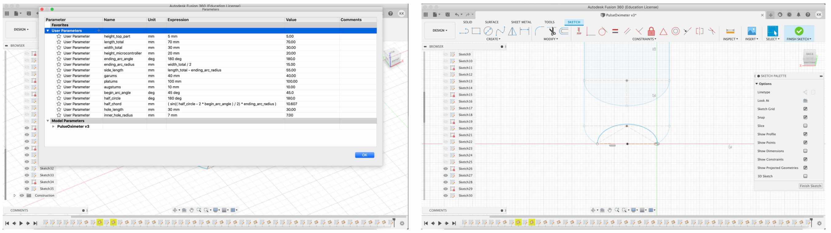
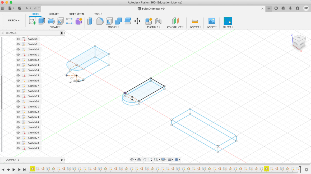
Then I returned to the original object and try to finish draw lines in different geometric planes.
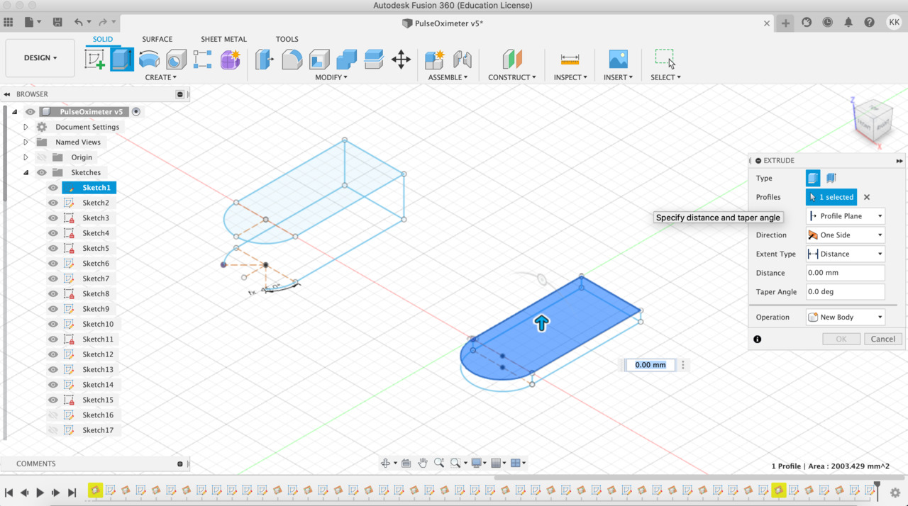
It's a part upper the red line (see above final sketch picture). - The most hardest thing - draw the arc (direction - inside). I try define parameter using a mathematical chord formula. I can't believe that I use mathematic like this after school graduated, ha!
- ❗When I zoom in I see that something is wrong - when I drew mathematical chord it didn't recognize side arc point and in a result inner circle isn't precise.
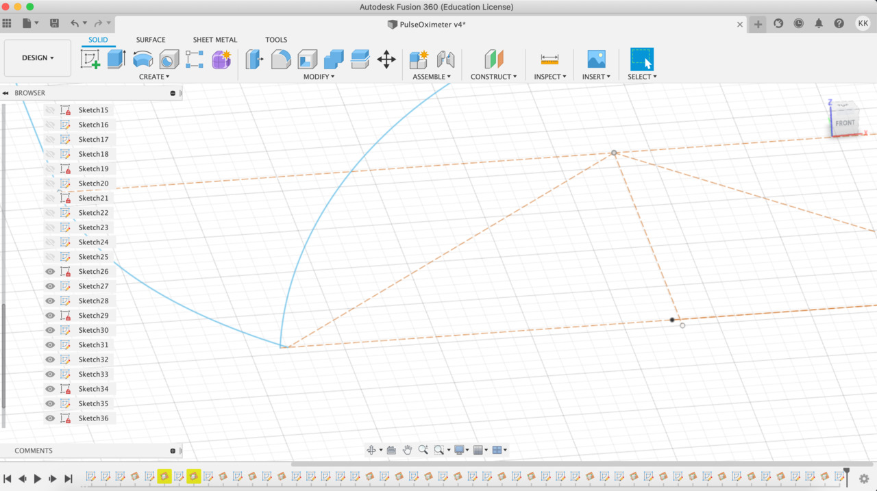
- ❗The second challenge - when I try extrude object it extrude just top layer, I am not sure, but maybe it's related with that I work in different geometric planes. I think so because I didn't succeed with a rectangular parallelepiped either. If still maybe my model has any problems with the joints, but with a rectangular parallelepiped it shouldn't be.
- This is the result of my effort modeling something related with my final project. It's not enough to print it and as I have just one day until finishes this week I will try make something other.
SCENE NO. TWO : MODELING & PRINT IT
NOT RELATED WITH FINAL PROJECT (.. or will to be in future)
- My inspiration - youtube "Hinge" (by Tomas Svitil).
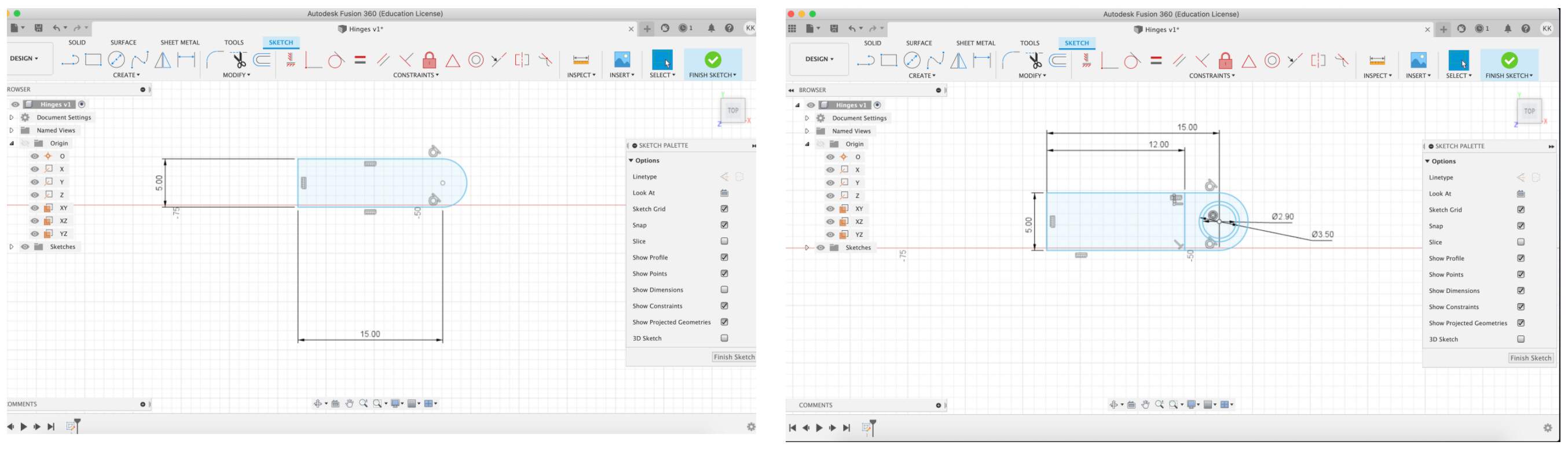
- Create sketch - 2-Point Rectangle, in Origin section choose XY plane and draw the rectangle 25x50. After that from Sketch section choose Circle - Center Diameter Circle (D=25 mm). Select Trim and cut out inside half of circle and rectangle side. Choose Tangent and select rectangle side and circle lines. After that create two circles, outer - 3.5 mm, inner - 2.9 mm. Create line 5x12.
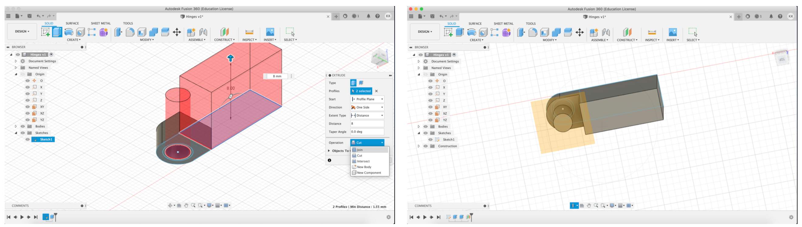
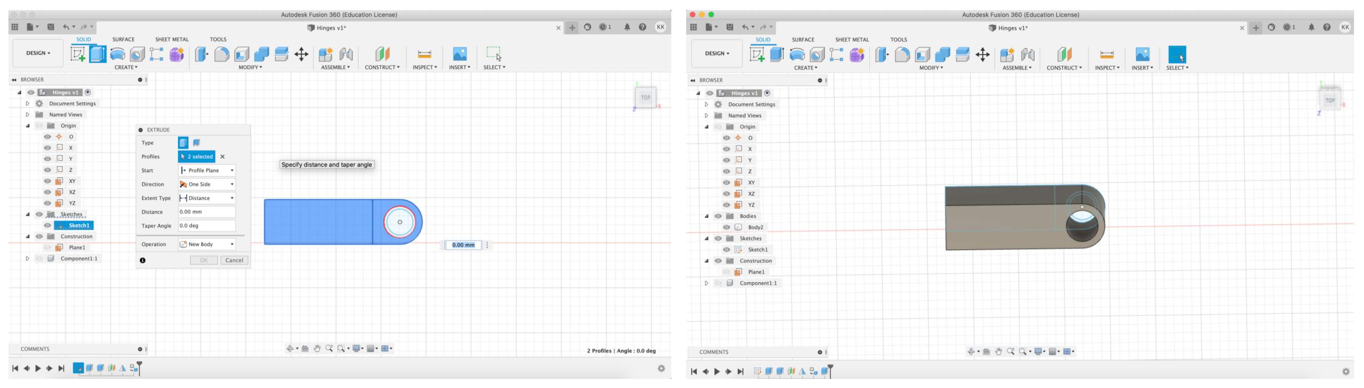
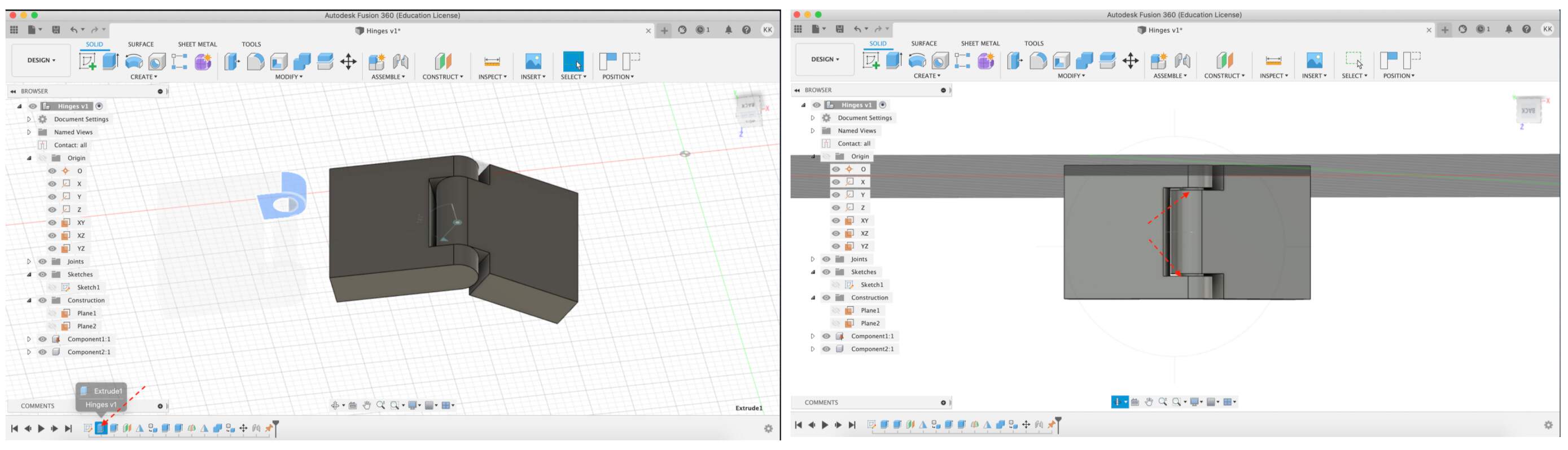
- Extrude the whole object. For that click Create - Extrude and in Distance box write 3mm. Then select body and shaft parts, again click on the Extrude and at this time distance is 8 mm and Operation - join. For mirroring this part first of all create Construct - offset plane, select the circle part and accept it.
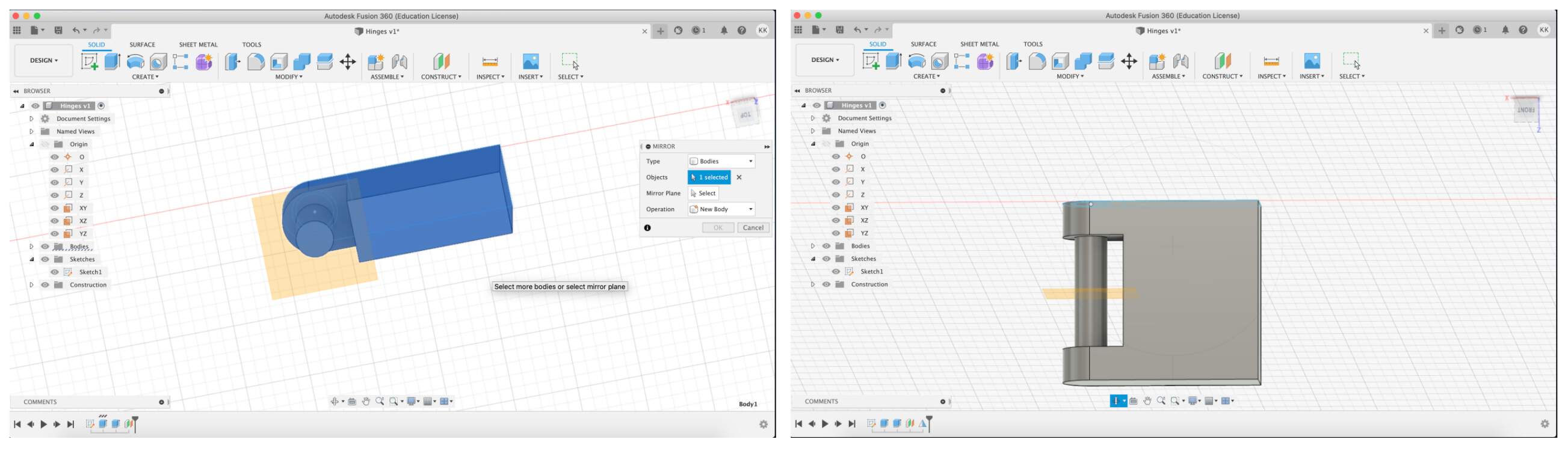
- Click on the Create and choose Mirror. Select body and for Mirror Plane choose previous created plane.
- In browser section click right mouse button on the new Body (in Bodies section) and Create Components from Bodies. After that - hide Component and plane and then start to create the second part of hinges.
- Extrude parts (don't touch circle parts) with Distance 10 mm.
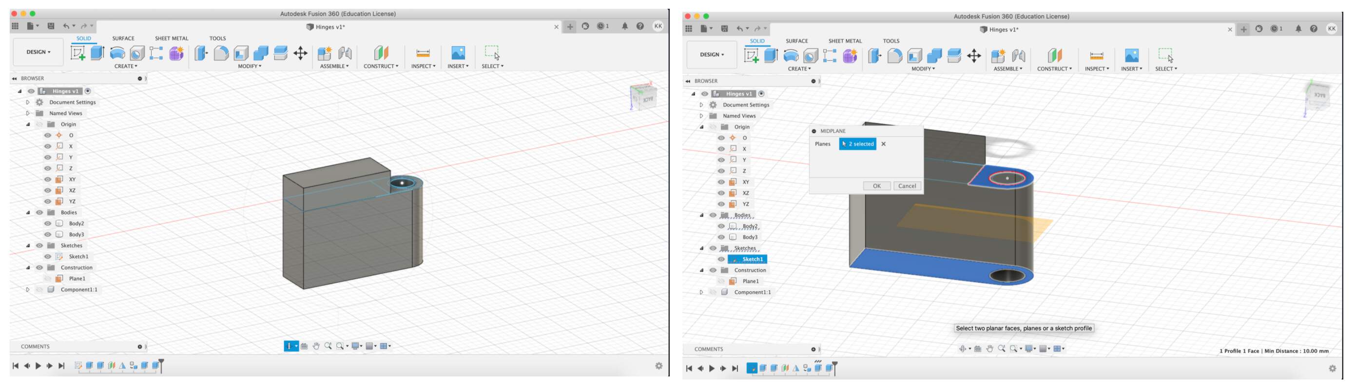
- Hide the body part, then Create - Extrude with Distance -3 mm. Enable the body part. Then go to Construct - Midplaneselect one part above, one below and accept it.
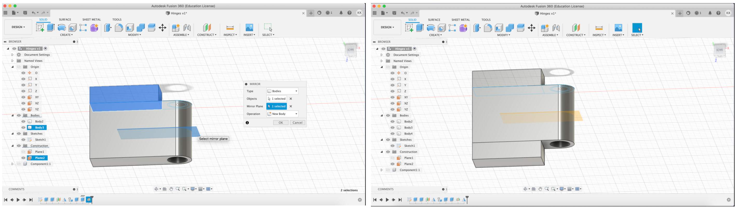
- Create - Mirror, Select top body and for plane - previous step created plane.
- Select all object's part, then Modify - Combine. Hide construction plane and sketch. Then in browser section click right mouse button on the new Body (in Bodies section) and Create Components from Bodies.
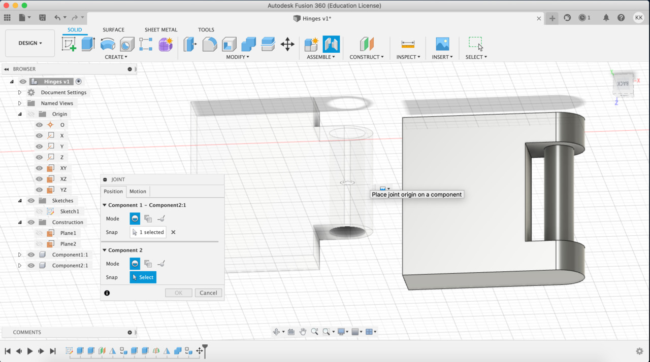
- Click on the Create, choose Move/Copy and separate parts. Then click on the Assemble, choose joint, choose these Components parts what will be rotated (circle parts). For motion choose Revolute and Rotation - Z axis.
- Click on the Assemble - Enable All Contact. Then New Contact Set, in browser section choose static Component, click on the right mouse button and select Ground. Then repeat - Enable All Contact.
- In Fusion history line click on the icon when you first time extrude object. Extrude distance to 3-0.3 mm
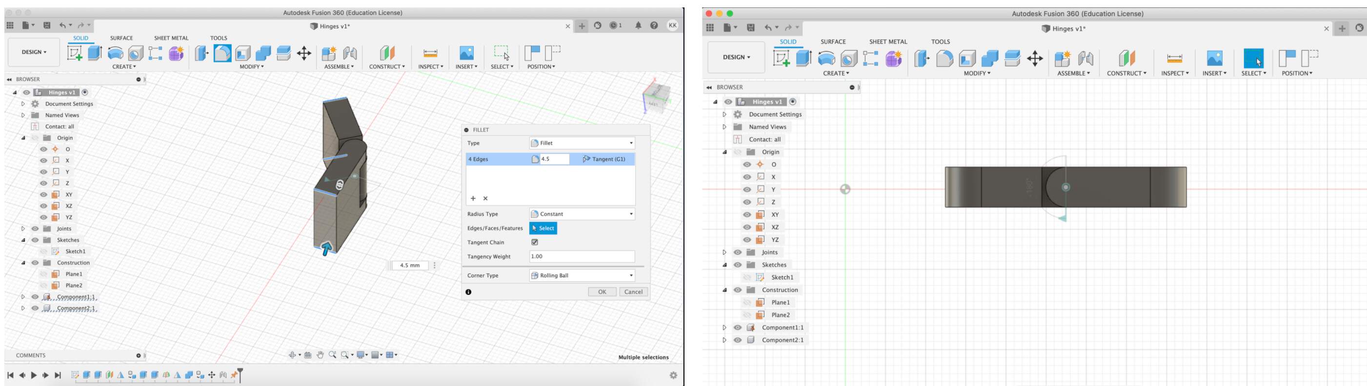
- Select corner edges, choose Modify - Fillet - Radius 4.5 mm. Align your static part to 180 deg.
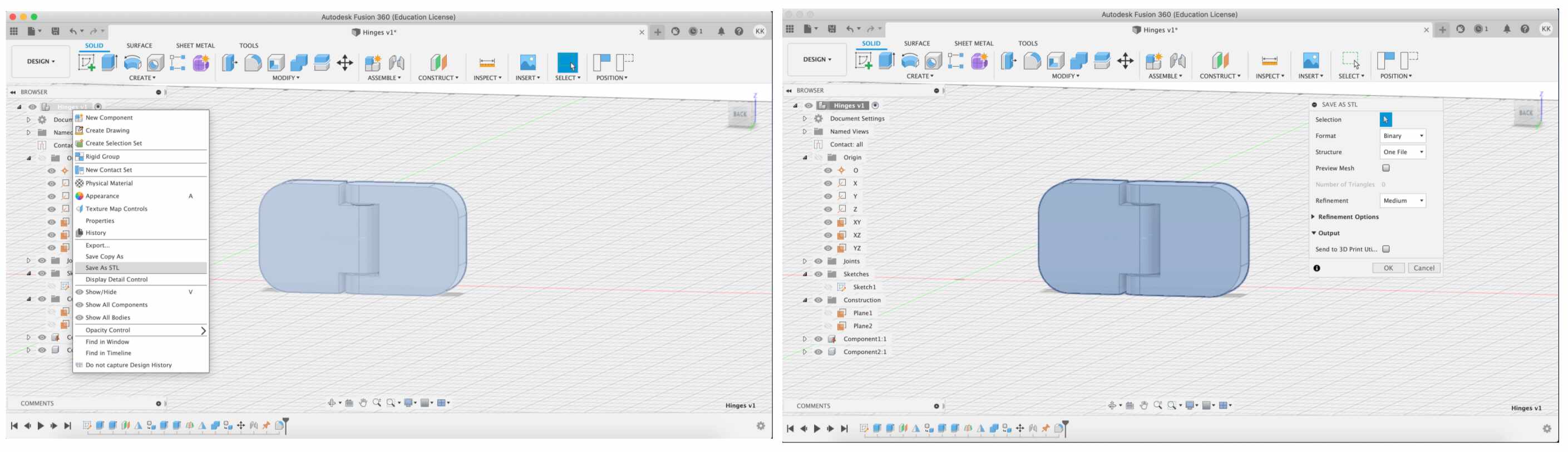
- CLick on the file in Browser section and choose Save as STL.
PROCESS & RESULT
PRINTING RESULT 1 : LULZBOT MINI
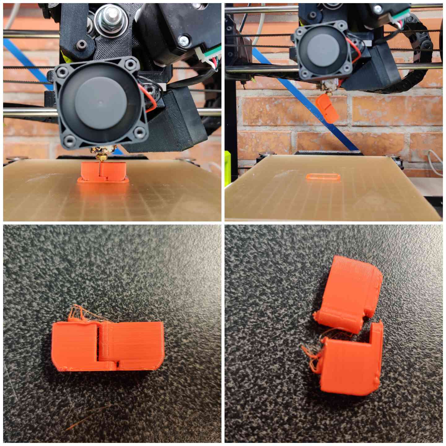
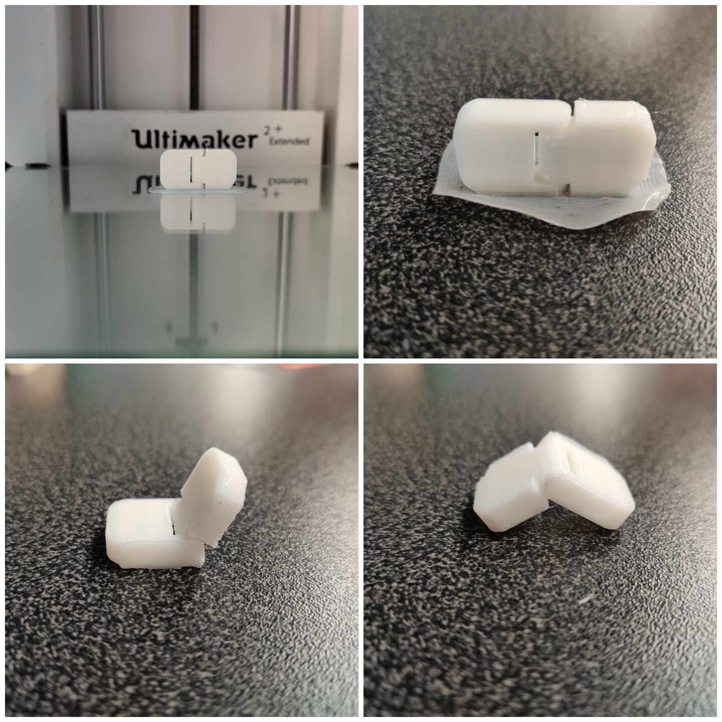
PRINTING RESULT 2 : ULTIMAKER 2+ EXTENDED
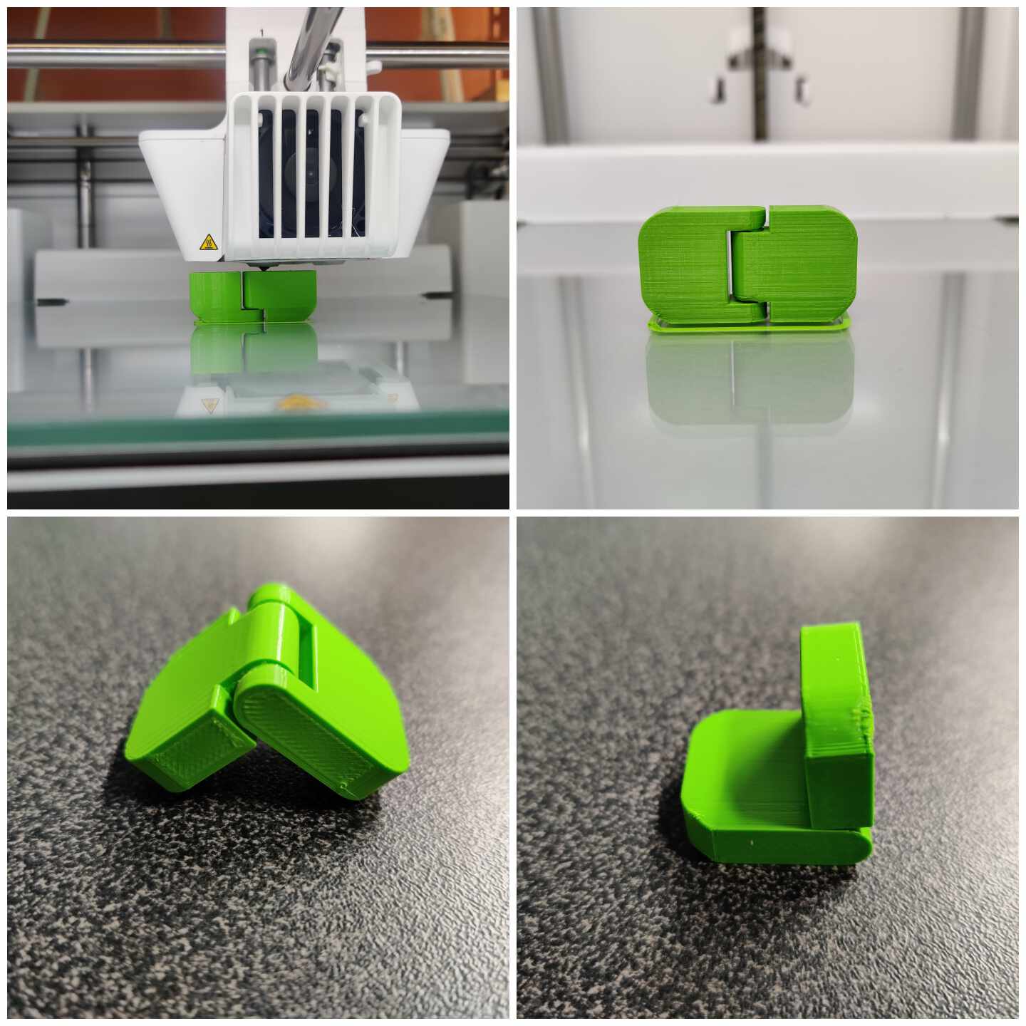
PRINTING RESULT 3 : ULTIMAKER S3
CONCLUSION
- For body printing 20% of infill is fine.
- In 3D printing process each changes affects time - if add a support that increases time, if work with double nozzle system and choose multiple color - again increases. Here we need to experiment between time management and quality. My revelation - with object's rotation can very good manage time, just need to find optimal position. I am not sure that I really understand physic - why in some position has a time increase, I just experiment with many position until I found optimal time result.
- Result of my effort modeling something related with my final project failed, but it was a good lesson to understand how important is start NOW work to final project!
- I am not so happy with Lulzbot result, but maybe my fault in that - in this case could be better if for build plate adhesion I chose Brim type. Anyway I think that result didn't work, because when I try rotate object it broke. Lulzbot not so precise, because when I comparing result from Ultimaker 2+ I saw that places which need to be separate in Lulzbot is connected.
- After Lulzbot failure for next experiment with Ultimaker 2+ I chose brim build plate type, but I think if I don't use that anyway result to be better. This printer is more precise than Lulzbot.
- The best hinges result I received from UltimakerS3 and I think it's because it is really precise printer with default settings.