Individual assignment:
Design, build, and connect wired or wireless node(s)
For the present practice of embedded networks and communications I have decided to use bluetooth wireless technology for communication between two nodes.
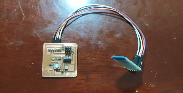
To focus clearly on the communication issue I have decided to use as nodes the boards made in the week of electronic design as Node # 1 and the training board designed in the week of input devices as Node # 2
The objective of this practice will be to connect the two nodes wirelessly through bluetooth technology and perform an action, in this case I will turn on some LEDs wirelessly.
What is Bluetooth?

Bluetooth is an industry specification for Wireless Personal Area Networks (WPAN) created by the Bluetooth Special Interest Group, Inc. that enables the transmission of voice and data between different devices using a radio frequency link in the 2.4 GHz ISM band.
Bluetooth is the communication protocol designed especially for low-power devices, which require a short transmission range and based on low-cost transceivers.
Devices that incorporate this protocol can communicate with each other when they are within range. Communications are carried out by radio frequency so that the devices do not have to be aligned and can even be in separate rooms if the transmission power is sufficient. These devices are classified as "Class 1", "Class 2", "Class 3" or "Class 4" in reference to their transmission power, with devices in a computer case being fully compatible.
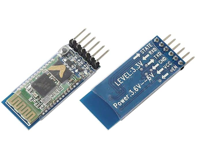
For this practical case, two Bluetooth HC-05 modules will be used

Development of the practice
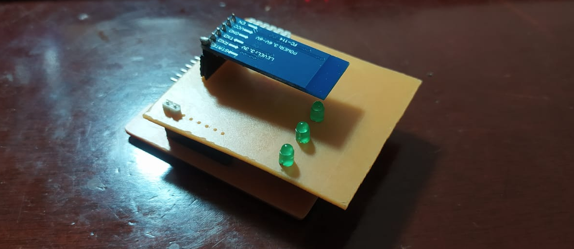
For this practice, first design in the EAGLE software a module compatible with the training board to connect the bluetooth module directly and additionally include three LEDs


Once the nodes are ready, we proceed with the configuration of the bluetooth modules, one as a master and the other as a slave.

Bluetooth modules configuration
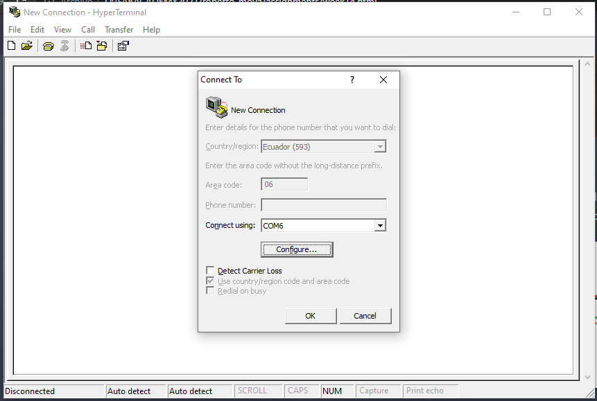
To configure the bluetooth modules, use use an FTDI cable and the Hyperterminal software which allows me to establish a serial communication with the HC-05 module to send AT switching commands.

Once the connection is made, we open the hyperterminal program, select the corresponding port and enter the following AT commands

MASTER

SLAVE

Node programming
Once the modules have been configured, the Nodes are programmed
NODE #1

#include <\SoftwareSerial.h\>

SoftwareSerial mySerial(2, 1); // RX, TX
int count;
int i;
void setup() {


  // set the data rate for the SoftwareSerial port
  mySerial.begin(9600);
  mySerial.println("Hello, world?");

  pinMode(0, INPUT);
  pinMode(3, OUTPUT);
}

void loop() { // run over and over

  int button = digitalRead(0);

  if (button == 1) {
    delay(300);
    i = 1;
    if (count <= 2) {

      count++;
    }
    else {

      count = 1;
    }

  }

  if (count == 0 && i == 1) {

    digitalWrite(3, 1);
    delay(300);
    digitalWrite(3, 0);
    delay(100);
    i = 0;
  }

  if (count == 1 && i == 1) {
    mySerial.println('x');
    digitalWrite(3, 1);
    delay(300);
    digitalWrite(3, 0);
    delay(100);
    i = 0;
  }

  if (count == 2 && i == 1) {
    mySerial.println('y');
    digitalWrite(3, 1);
    delay(300);
    digitalWrite(3, 0);
    delay(100);
    i = 0;
  }

  if (count == 3 && i == 1) {
    mySerial.println('z');
    digitalWrite(3, 1);
    delay(300);
    digitalWrite(3, 0);
    delay(100);
    i = 0;
  }

}
NODE #2

int i = 0;
int opcion = 0;
boolean iniciar = false;
int resultado;
void setup() {
  // put your setup code here, to run once:
  Serial.begin(9600);

  pinMode(2, OUTPUT);
  pinMode(3, OUTPUT);
  pinMode(4, OUTPUT);
}

void loop() {
  // put your main code here, to run repeatedly:


  if (Serial.available() > 0) {
    char letra = Serial.read();

    if (letra == 'x') {
      digitalWrite(2, 1);
      digitalWrite(3, 0);
      digitalWrite(4, 0);
      Serial.println("LED 1");
      delay(100);

    }

    if (letra == 'y') {
      digitalWrite(2, 0);
      digitalWrite(3, 1);
      digitalWrite(4, 0);
      Serial.println("LED 2");
      delay(100);

    }

    if (letra == 'z') {
      digitalWrite(2, 0);
      digitalWrite(3, 0);
      digitalWrite(4, 1);
      Serial.println("LED 3");

      delay(100);

    }


  }

}