Group assignment:
Measure the power consumption of an output device.
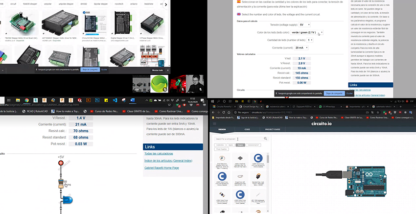
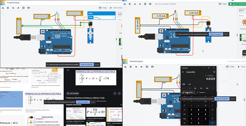
Practically we were searching up all about different devices that we can use for this practice. Power consumption measured in watt (usually in milliwatt, mW) is the correct term for low power applications but all too often the current consumption measured in ampere (usually milliamperes, mA) is used instead. As the power is just the operating voltage multiplied by the current, this is trivial for fixed voltage operations but becomes more tricky to estimate when using batteries that discharge and the voltage changes over time and loading conditions. It is usually the energy consumption measured in Joules (usually in micro joules, µJ) that determines how much energy is actually drained from the battery to complete a specific task. The energy consumption will be the integral of the power consumption over the time needed to perform the operation. Again, with static signals this would be a simple multiplication of power consumption and the time but with varying signals this will demand more complex analysis. link with more information
More details before the practice. I was checking information about displays because I would like to get some information about the input devices in this case flex sensors. The idea is to propose some kind of reading where I can represent degrees of flexibility in every single finger.
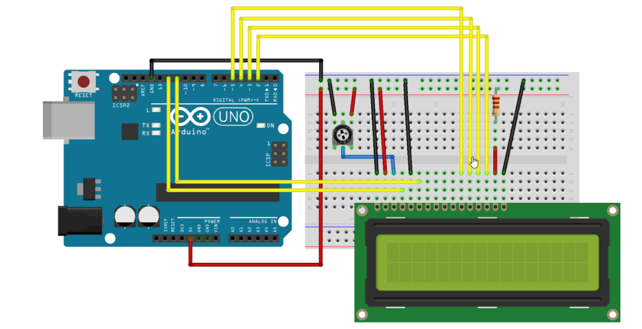
The LiquidCrystal library allows you to control LCD displays that are compatible with the Hitachi HD44780 driver. There are many of them out there, and you can usually tell them by the 16-pin interface. This example sketch prints "Hello World!" to the LCD and shows the time in seconds since the Arduino was reset. The LCDs have a parallel interface, meaning that the microcontroller has to manipulate several interface pins at once to control the display. The interface consists of the following pins: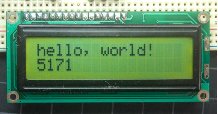
- A register select (RS) pin that controls where in the LCD's memory you're writing data to. You can select either the data register, which holds what goes on the screen, or an instruction register, which is where the LCD's controller looks for instructions on what to do next.
- A Read/Write (R/W) pin that selects reading mode or writing mode
- An Enable pin that enables writing to the registers
- 8 data pins (D0 -D7). The states of these pins (high or low) are the bits that you're writing to a register when you write, or the values you're reading when you read.
- There's also a display constrast pin (Vo), power supply pins (+5V and Gnd) and LED Backlight (Bklt+ and BKlt-) pins that you can use to power the LCD, control the display contrast, and turn on and off the LED backlight, respectively.
- The process of controlling the display involves putting the data that form the image of what you want to display into the data registers, then putting instructions in the instruction register. The LiquidCrystal Library simplifies this for you so you don't need to know the low-level instructions.
- The Hitachi-compatible LCDs can be controlled in two modes: 4-bit or 8-bit. The 4-bit mode requires seven I/O pins from the Arduino, while the 8-bit mode requires 11 pins. For displaying text on the screen, you can do most everything in 4-bit mode, so example shows how to control a 16x2 LCD in 4-bit mode.
link with more information
Then,
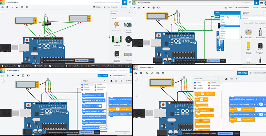
We started the practice with Tinkercad, but first .
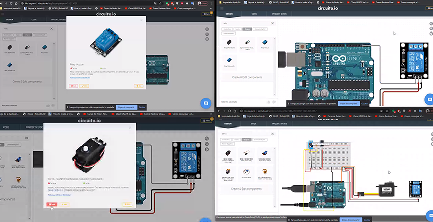
Preparing the elements.
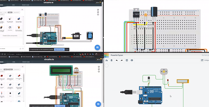
Working on Tinkercad
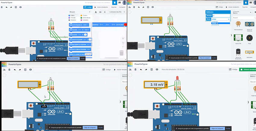
Connecting measurement tools.
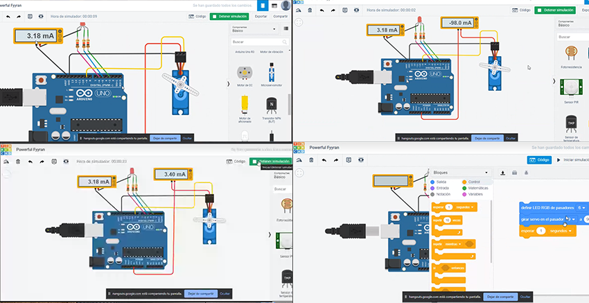
Having the results.
Individual Assigment
Add an output device to a microcontroller board you've designed, and program it to do something.
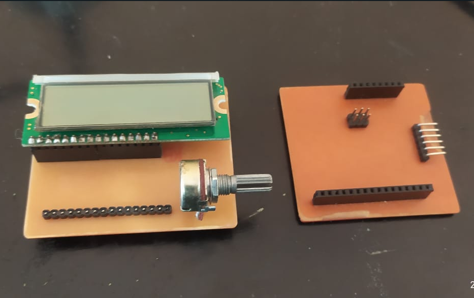
For the present practice I have decided to test the operation of a 16x2 LCD screen as an output device, for which I am going to use the training board that I manufactured in the week of INPUT DEVICES, for this I designed a PCB as a module which I Peritio connect the device directly to the training plate and test the operation.
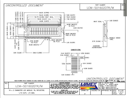
The LCD screen that I use is the LCM-S.1602DTR/M, for which initially check the configuration of its ports in its datasheet to make an adequate connection with the microcontroller
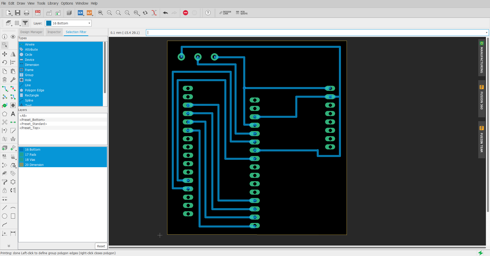
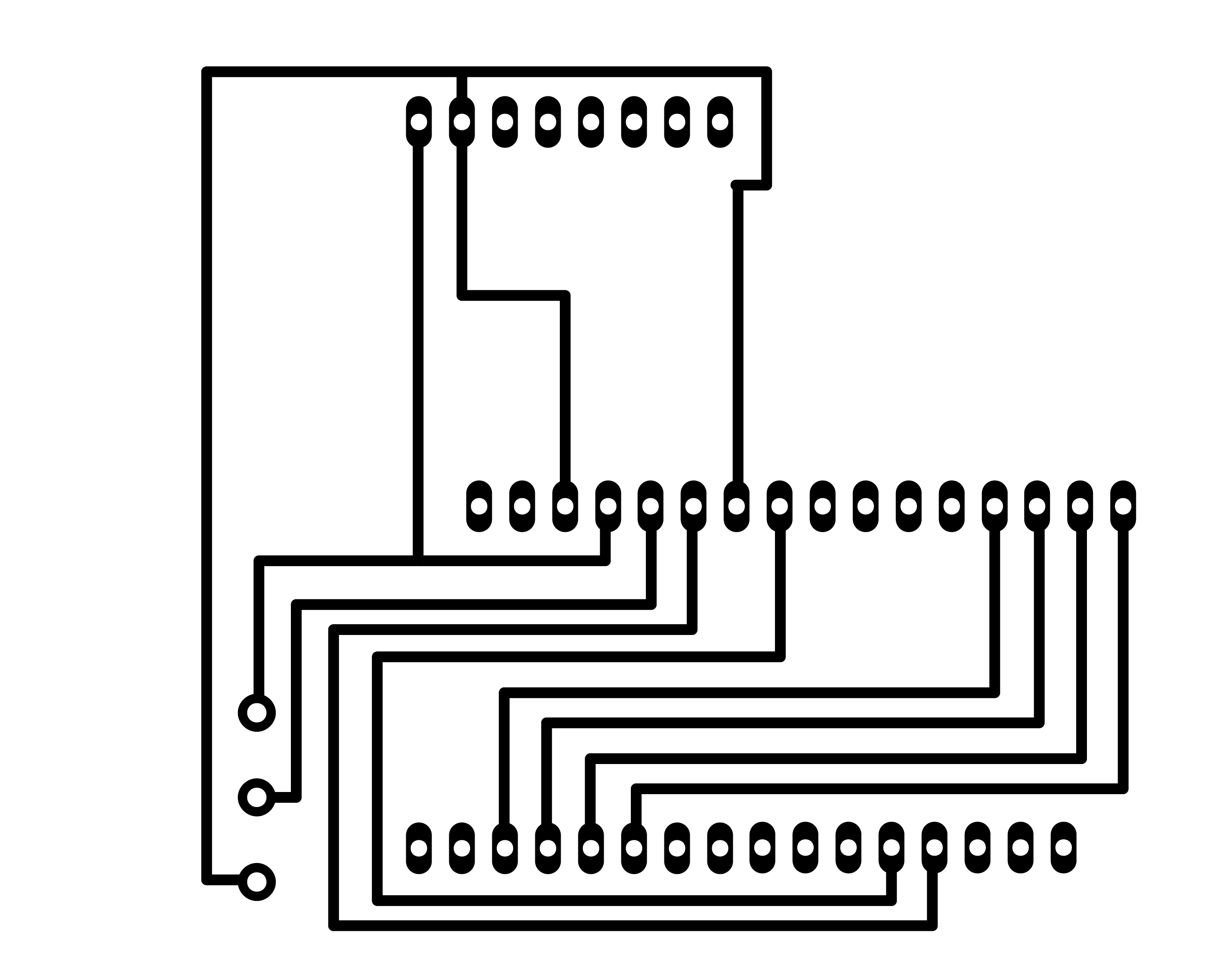
Once I was clear about the connection of the LCD screen, I proceeded to design the module using the eagle software.
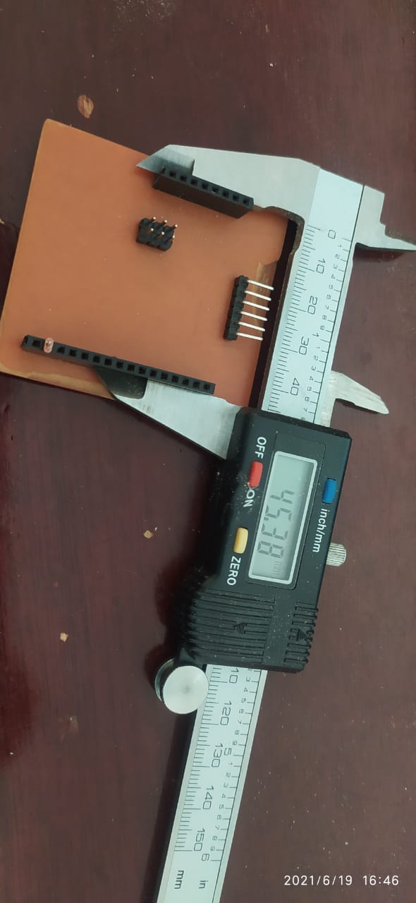
Before starting the design, I obtained the measurements of the training plate so that the module coincides without problems
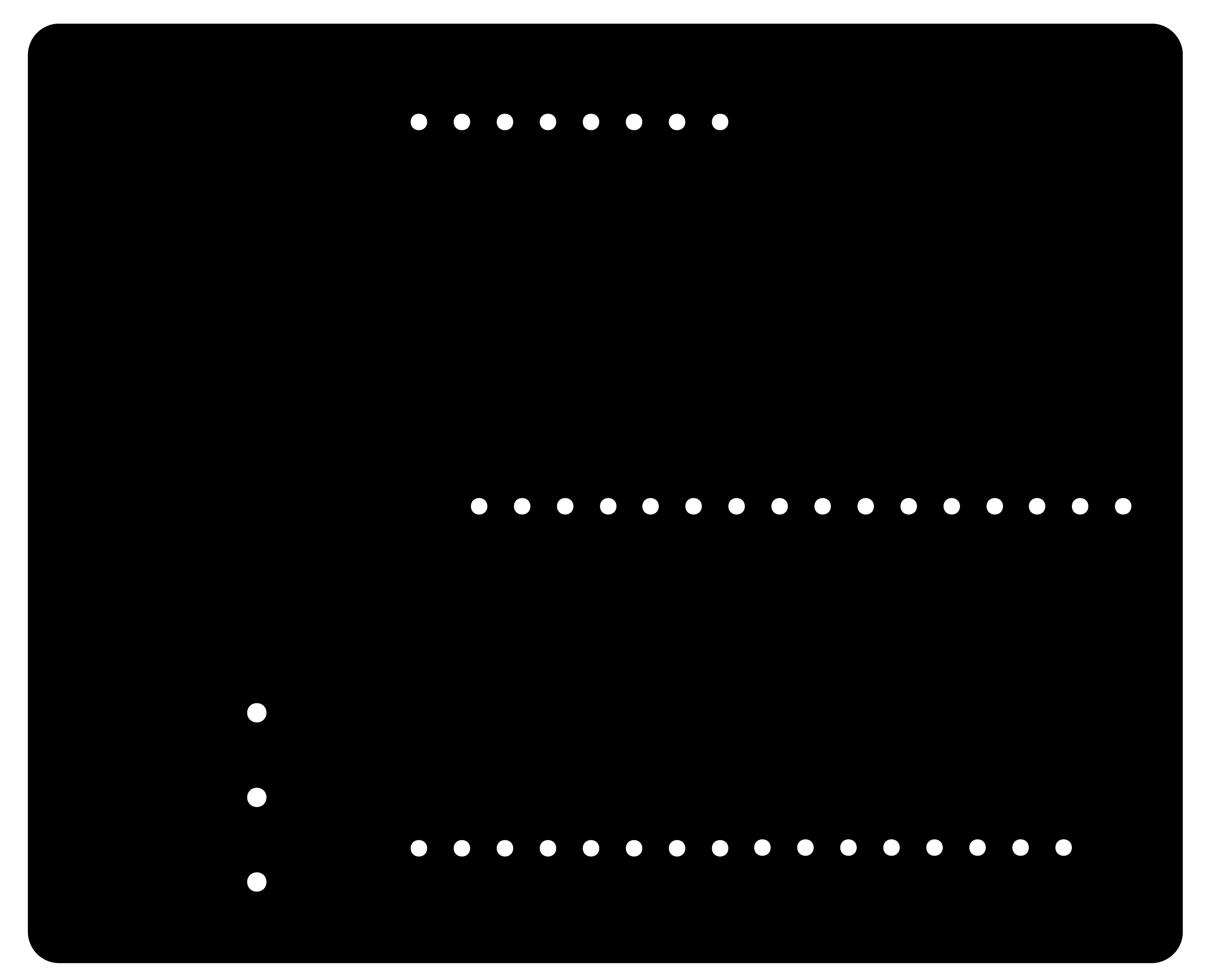
Module layout for LCD in EAGLE software
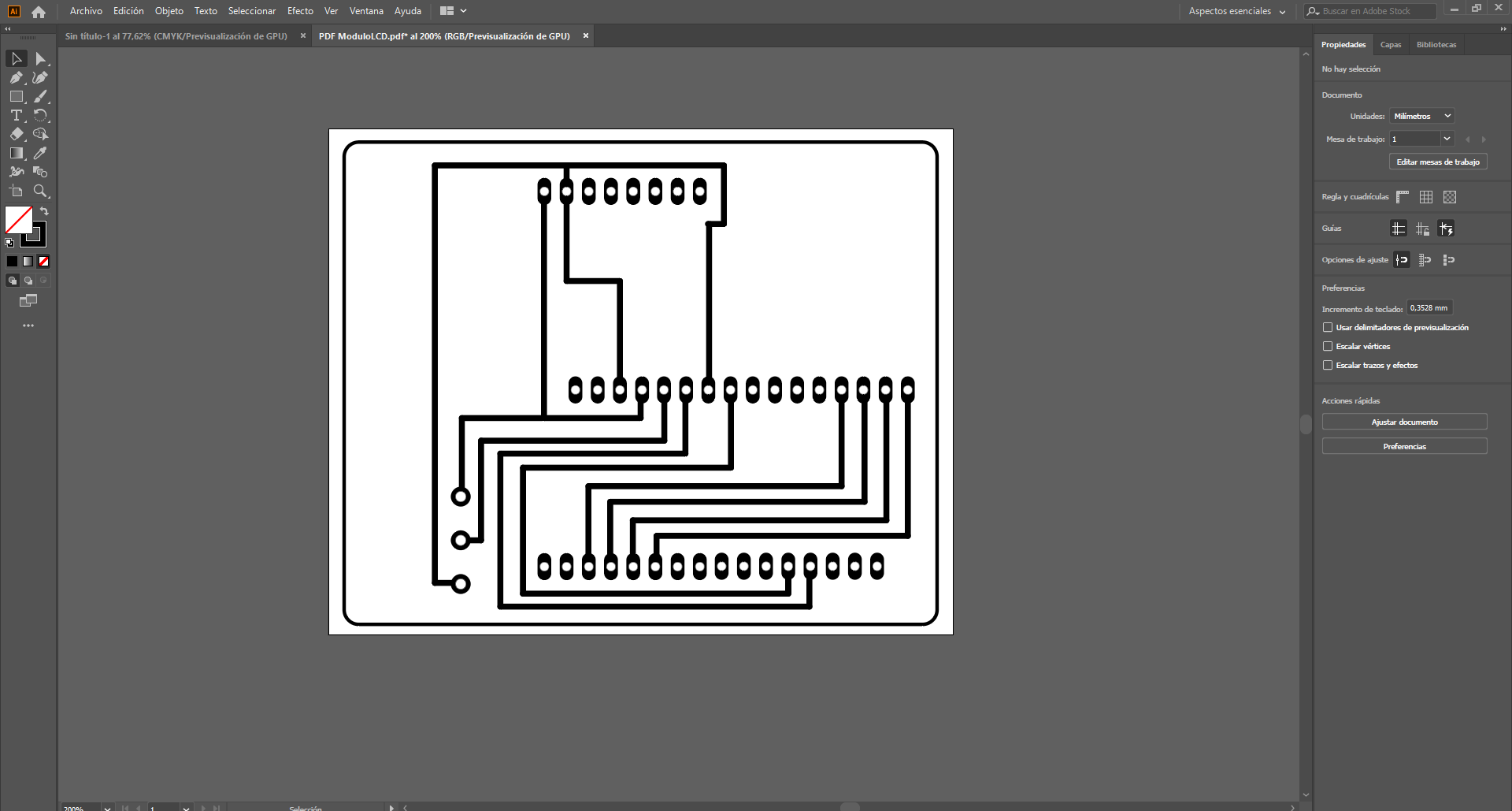
Once the design is ready, it is exported in PDF to be able to edit it and create the manufacturing files
Once the design is ready, it is exported in PDF to be able to edit it and create the manufacturing files. Use the Adobe Illustrator software to edit the file and improve the resolution, also create the different cut, drill and raster files and save them in PNG format with a resolution of 1000 PPP.
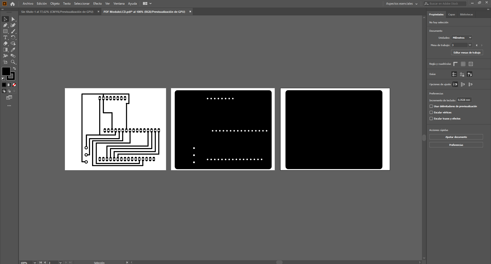
Then the raster, cut and perforation files were generated using the fabmodules tool.
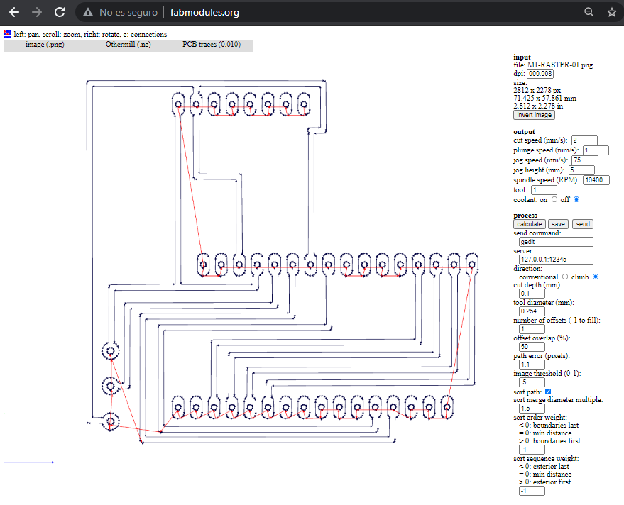
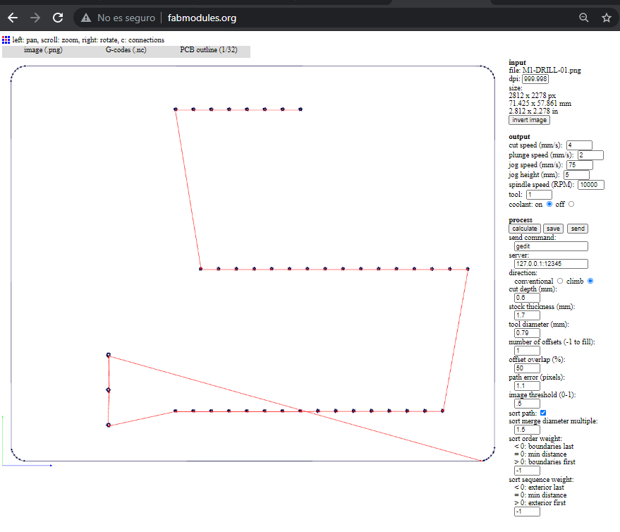
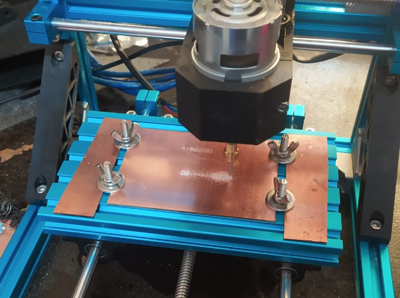
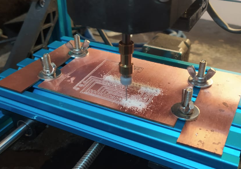
With the fabmodules tool we create the files in G code, to be used in the 1610 CNC milling machine. The software used to control the machine is GRBL.
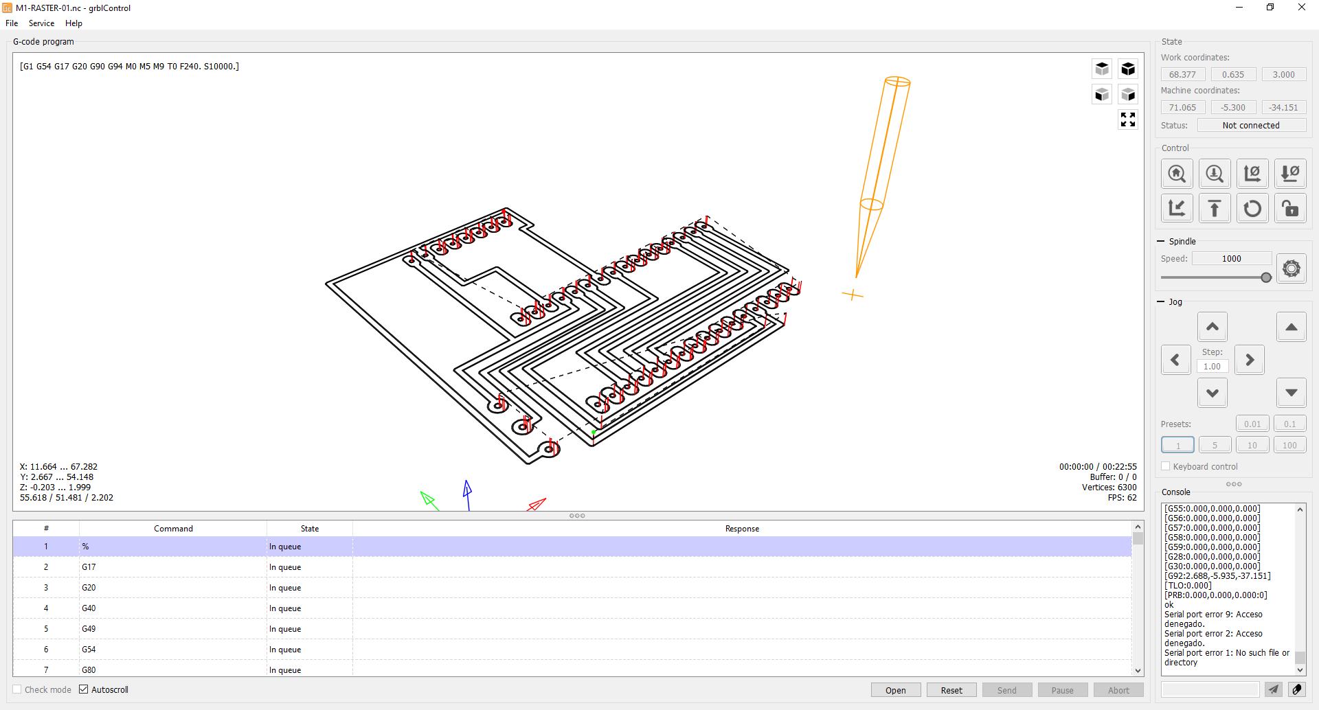
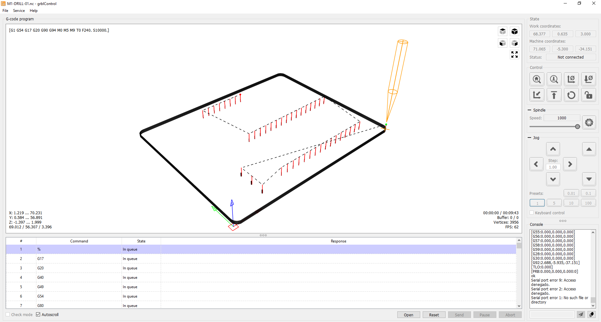
Machining process
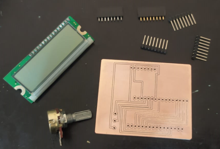
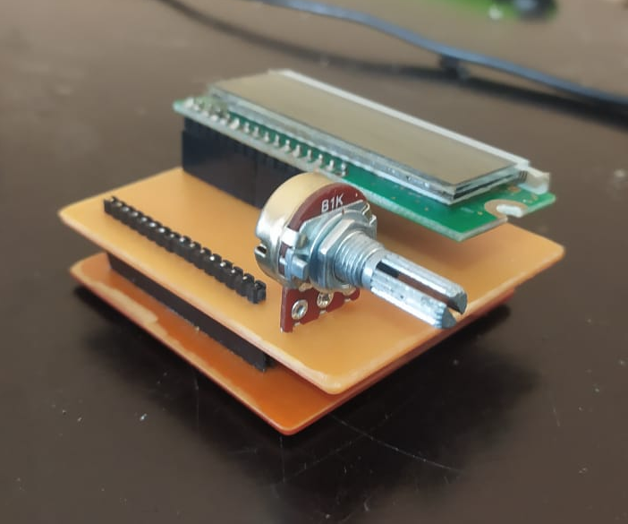
Component soldering process
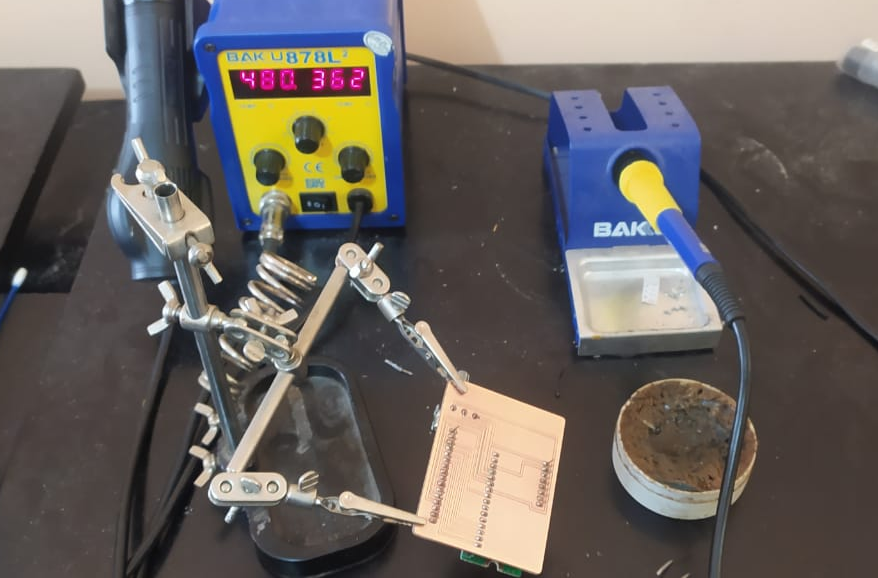
Once the soldering process of the components was finished, the module board was connected to our training board.
Programming
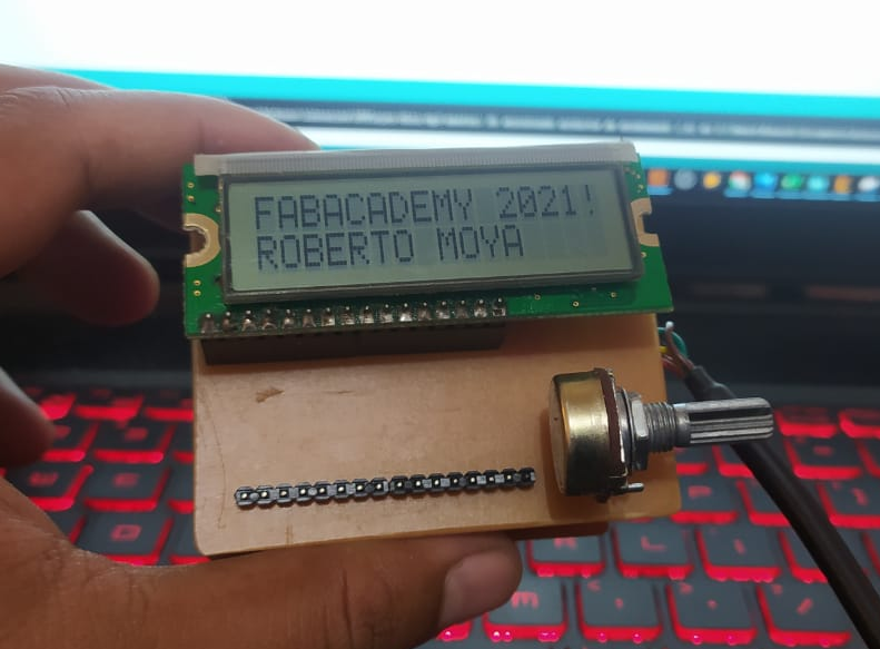
// incluir librería del LCD: #include// inicializar la librería con los números de los pines de interfaz LiquidCrystal lcd(12, 11, 2, 3, 4, 5); void setup() { // configurar el número de columnas y filas de la pantalla LCD: lcd.begin(16, 2); // Imprimir un mensaje en la pantalla LCD. lcd.print("FABACADEMY 2021!"); lcd.setCursor(0, 1); lcd.print("ROBERTO MOYA"); } void loop() { // coloca el cursor en la columna 0, línea 1 // (nota: la línea 1 es la segunda fila, ya que el conteo comienza con 0): } Test run
Conclusion
- Verify the electronic elements before starting with any design, you can have the same problem I got.
- Everything goes better if you have a plan before, I didn´t plan anything before this assignment, so I can say I was lucky.
- Work with Eagle it´s still complicated for me and any kind of design takes me hours, so the recommendation here is be patient.
- The best way I found actually is work first with the virtual tools befores start working with the real electronic elements.
Files