8. Computer controlled machining
This group assignment consisted in testing runout, alignment, speeds, feeds, and toolpaths for our machine and documenting our work.
To do this assignment we designed a part that we can cut two times in a row and assemble with itself. To test different toolpaths we designed a special kind of joint that needs 3D milling, the rest of the part being cuttable with 2D milling. As Neil made it very clear that this week was no time to break a milling tool or worst, burn the CNC or the FABLAB by setting foolish cutting speeds, we decided to reasonably test the speeds and feeds just by looking at the literature and making the adequate calculus regarding the datasheet of the cutting tools. For the runout test we just measured the part and compared the measurement with the expected length. For the alignment test, we assembled the parts together and looked if their joints were correctly aligned.
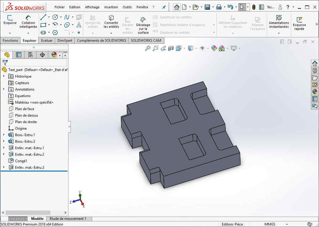
The part is first designed in Solidwordks, including features such as chamfers or fillets.
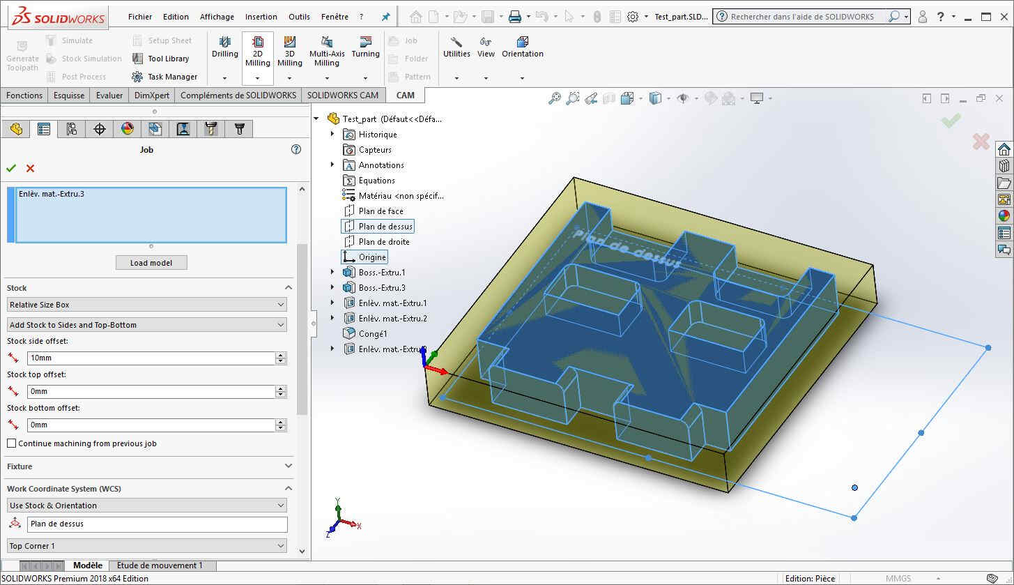
Then, a new CC job is created:
Computing the machining speed for a CNC is a bit more involved than other tools. We can make an analogy with the laser cutter by comparing the laser power rate to the tool’s RPM. However, the laser’s power deposition is a more linear phenomenon than tearing chips from the wood, and there are more variables here.
The parameters of the CNC bit are first checked on the website:
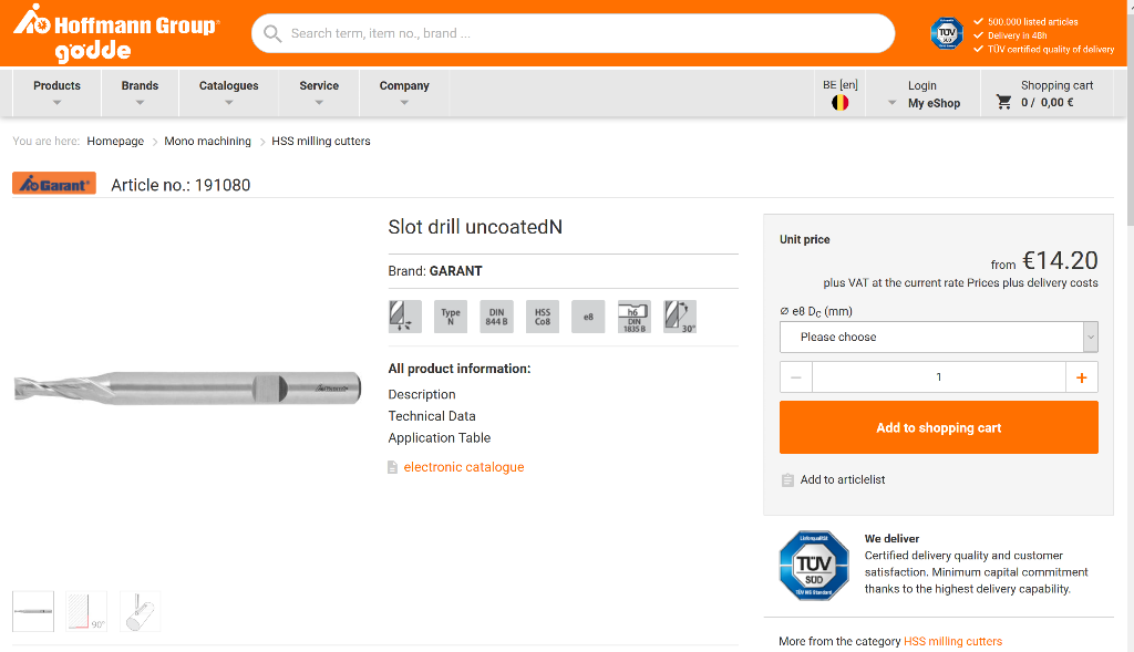
In our case, we end up with:
- diameter: D=6mm
- teeth: N=2
- maximal stepdown: 2mm
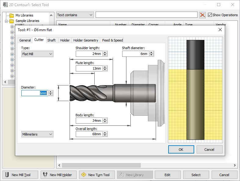
The geometry of the bit is encoded into Solidworks:
The diameter us compute the cutting speed V_c, defined as the contact speed of the bit against the material as a function of \Omega (RPM), (source: https://www.ns-tools.com):
To compute the feed per tooth F_t, we have the following:
Where V is the feed rate, the XY motion speed of the machine. The feed per tooth is a good indicator of the chip size, and is quite often the most critical parameter to select.
For both MDF and plywood, we found online that F_t = 0.3mm was a good value. We can pick the RPM freely, so we choose one of the highest values available for us, \Omega=9000 rpm. From this we deduce:
The software already performs this calculations for us, based on the fixed parameters:
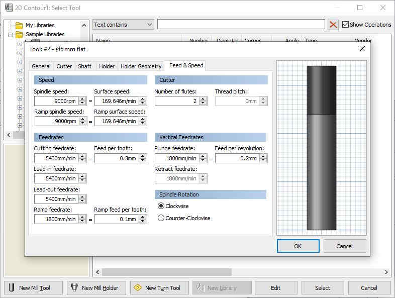
The stepdown can be picked freely, as long as it is below the maximal allowed value. A smaller stepdown increases the number of steps, so we choose a value of 1.5mm.
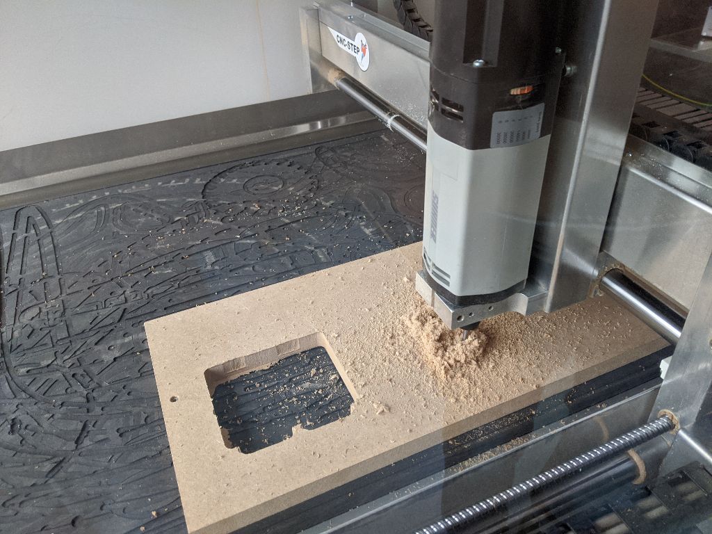
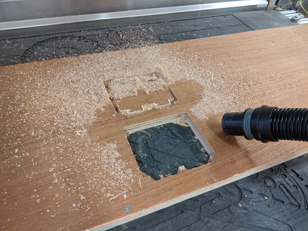
Cutting
Cutting was pretty fast, lasting only a few minutes. We found that the stepdown we picked was a bit too high. This resulted in audible chatter, but no visible errors the finished part.
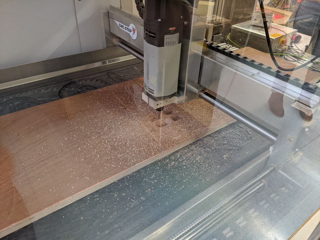
We performed the same gcode on plywood. For this tougher material, the stepdown should be even smaller, but the job completed without issue.
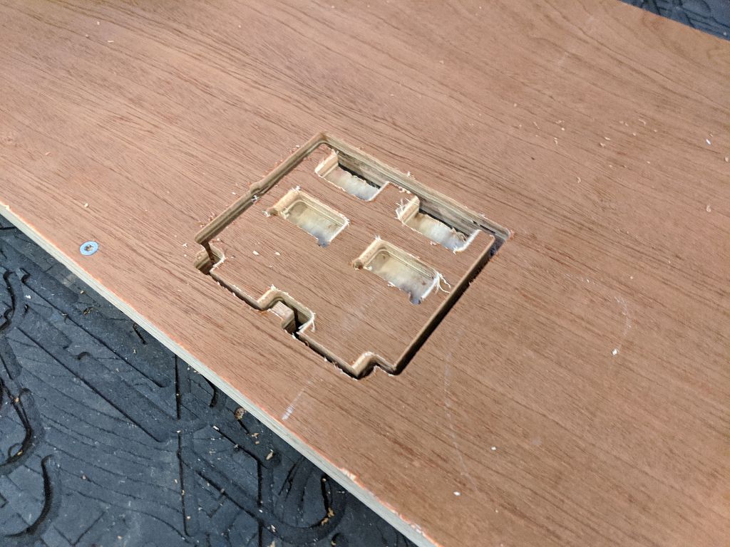
We cut a second copy to test the fitting. Notice that small tabs allow the part to remain attached to the stock during the last few cuts.
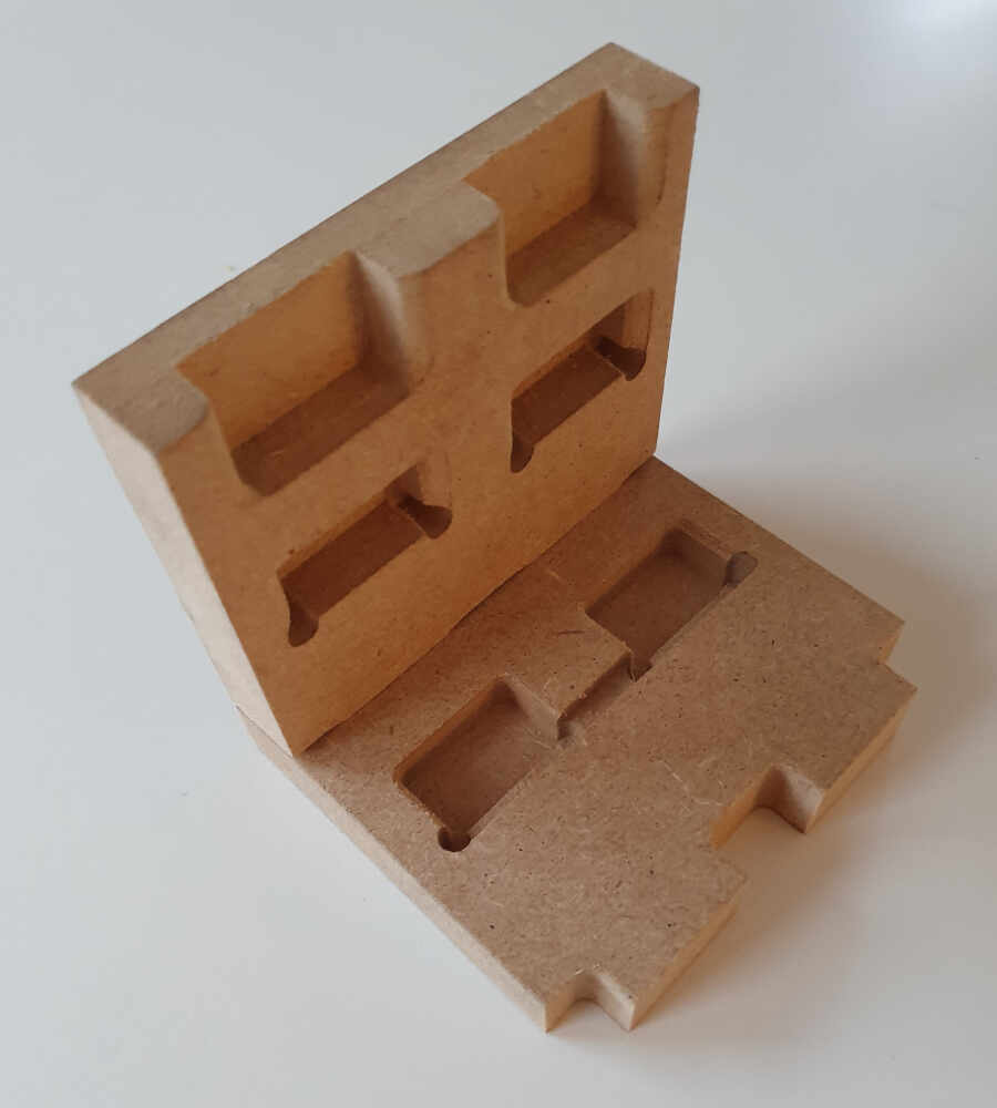
As planned, the fitting was pretty tight, as we did not include any offset in the design. For both types of wood, pressing the parts together is enough to get a strong bond.
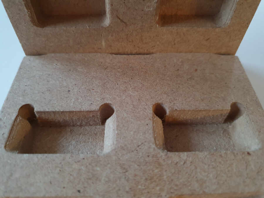
Notice that the part at the bottom has a defect due to an error in the gcode: an unwanted line was traced when drilling the holes on the corners.
A view from the back shows the fitting to be successful.
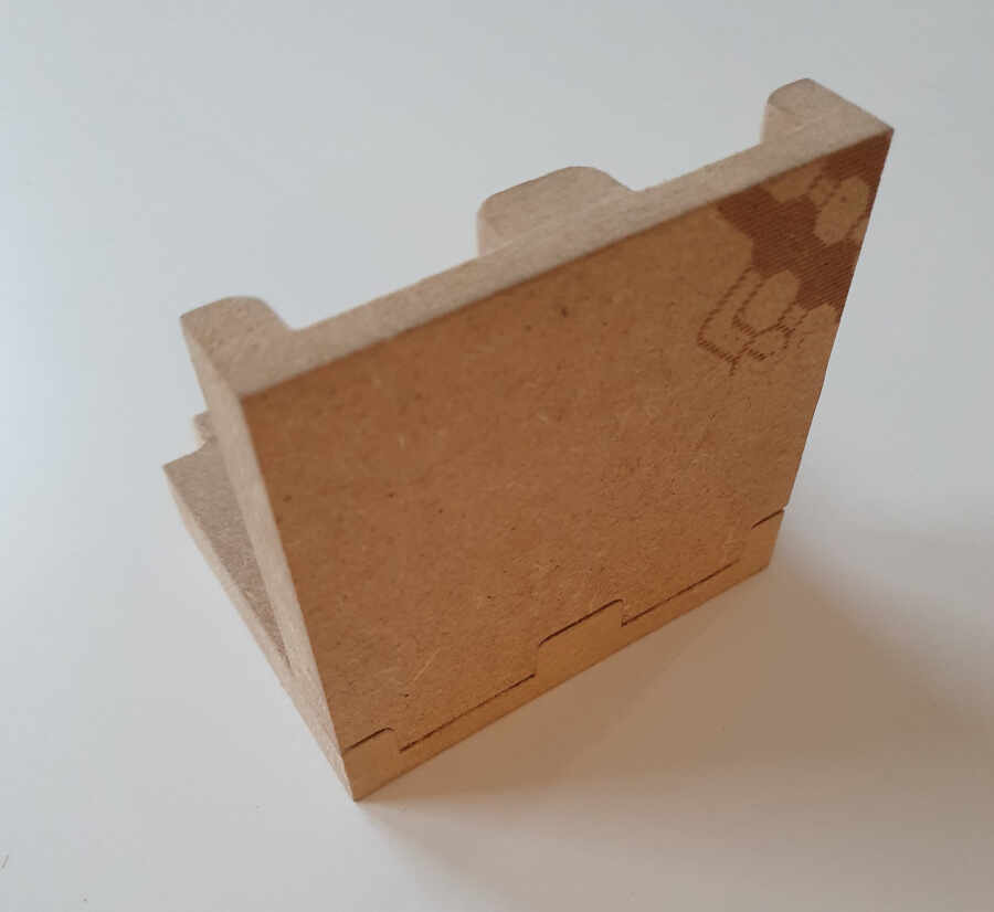
Regarding the runout, we estimated that the bit was deviated from about 0.2mm, resulting in slightly oversized parts. This can most likely be reduced with a more reasonable stepdown, as signlificantly less lateral force would be applied on the tool. In any case, it is a good practice to include 0.2-0.4mm of play in the designed parts.