Week 09:Input Devices
Assignments:Individual assignment:
* Measure something: add a sensor to a microcontroller board that you have designed and read it
Group assignment:
* Probe an input device's analog levels and digital signals
Google drive with all files
Invidual Assignment
DHT11 Temperature and Humidity Sensor
As a input device for my board I decided to make a simple weather station. It will cointaint one sensor ,DHT11 digital sensor, it measures the humidity and temperature in the air. Unfortunately Tinkercad Circuts does not support that exact sensor so I will have to test everything on real model.First thing will be checking the data sheet of the sensor: DHT11 Sensor Datasheet
On the 5th page we can find there a "Typical Application" chapter with figure.

This gives us many valuable information about how to connect the sensor properly to the board.
Now lets look at the real sensor.
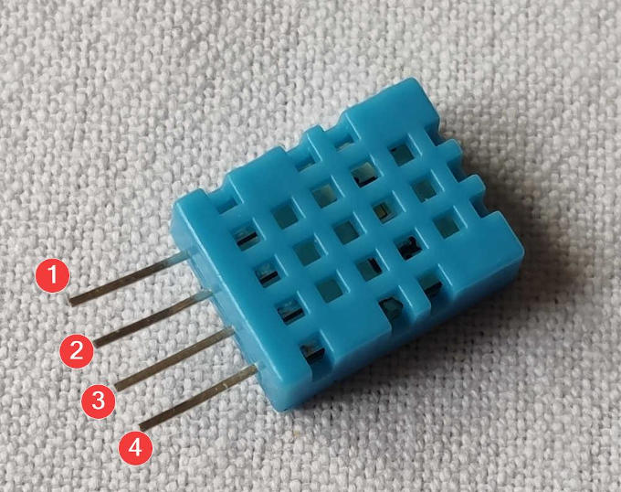
From the data sheet I know that:
Pin 1 is VCC
Pin 2 is DATA
Pin 3 is NC(Not Connected)
Pin 4 is GND
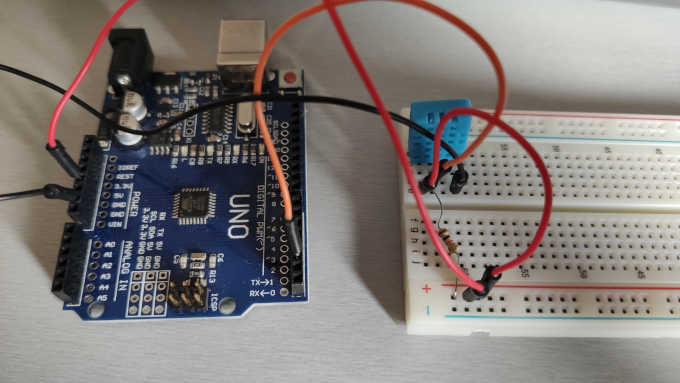
With this knowladge I can connnect the sensor to the board with jumper wires.
After few seconds the board looks like this:
I have also learned that to operate the sensor fully I need to download new library for the Arduino IDE and include it into the code sketch. After a brief look into the web I found quite simple library for the sensor:Mark Ruys DHT Sensor Library
To make sure I will write my code correctly I have to read the library 1st, there I will find all necessary information as well as all necessary commands to read data from the sensor.
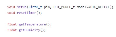
Here we can see few valuable information that we can read from the Library.
void setup(uint8_t pin, DHT_MODEL_t model=AUTO_DETECT);Is a code that tells us how to define the sensore into our main code.
float getTemperature();float getHumidity();Tells us what are the commands to make a readout from the sensor and know what is the temperature and humidity.
So after this prep I can finally start writing the code.
#include "DHT.h" //Including the sensor library
#define DHT11_PIN 2 // defining the physical sensor - telling the board on which PIN the sensor data in supplied
DHT dht; // declaration needed for DHT library

void setup() //setup void in which we state things that we want to declare once for whole code operation like pins etc.
{
  Serial.begin(9600); // declaration of badurate need to communicate with board on serial monitor
  dht.setup(DHT11_PIN); // declaration of type of the sensor applied for library purpose
}

void loop() // loop void is a section that is repeated continuously
{
  int humm = dht.getHumidity(); // using command supplied by library to read value of humidity and signing it into a int valuable
  Serial.print(humm); //printing the value on serial monitor
  Serial.print("%RH | "); // adding information about the value

  int temp = dht.getTemperature(); // using command supplied by library to read value of temperature and signing it into a int valuable
  Serial.print(temp); //printing the value on serial monitor
  Serial.println("*C"); // adding information about the value

  delay(5000); //delay between next readout
}
After a while code looks like this and after sucesfull uploading to the board gives us following result: Since the DHT11 sensor was quite fun I decided to test more sensors.
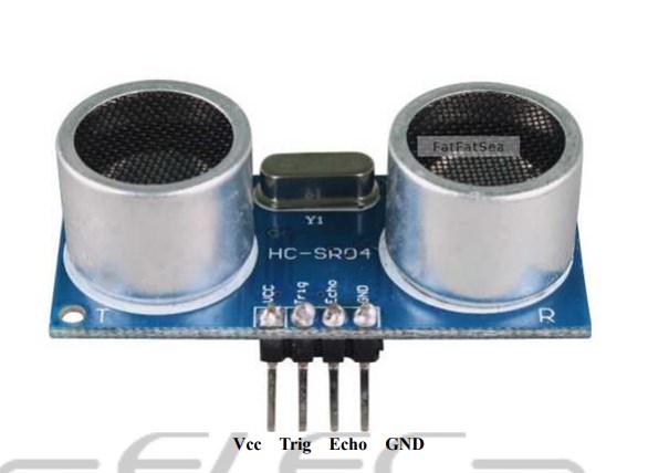
Ultrasonic Distance Sensor HC-SR04
Next will be a Ultrasonic Distance Sensor HC-SR04, it works in distance of 2-200 cm.But how it works?
It emits ultrasound at 40000 Hz which travels in the air and as soon the ultrasound hits any object it bounce back to the reciever module. By knowing the speed of sound and travel time of the signal we can calculate the distance of the object.
Before doing anything lets starts with datasheet!
Ultrasonic Ranging Module HC - SR04 Datasheet
This datasheet gives us some technical information about the part and as well a Pinout of the PCB board. The Pinout it also clearly marked on the real part.
Firstly I have designed the wirering in Tinkercad Circuts.
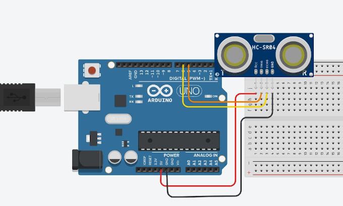
Next step was to make a real life circut.
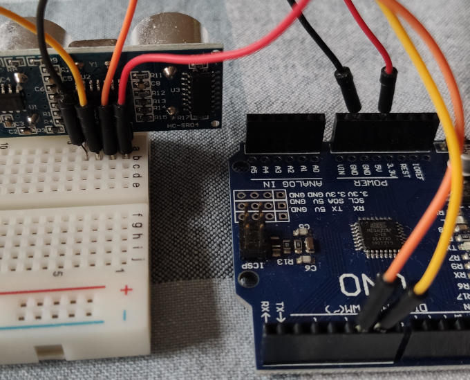
While to circut is ready now it is time to write the code, so let open Arduino IDE and start coding.
After few minutes of coding and tinkering, this is the output:
const int triger = 5; // seting the pinouts
const int echo = 6; // seting the pinouts
long dur; // seting the variable for duration of the wave travel used to calculate the distance
int dist; // seting the variable for distance
void setup() {
pinMode(triger, OUTPUT); // Sets the triger pin as an Output
pinMode(echo, INPUT); // Sets the echo pin as an Input
Serial.begin(9600); //Command for the serial communication
}
void loop() {
digitalWrite(triger, LOW); // At the beginning of "measurement loop" I have to make sure that the triger is clear (on low state)
delayMicroseconds(2);
digitalWrite(triger, HIGH); // Now I can start measurements with setting the sending probe into high = sending the signal
delayMicroseconds(10); // time for singal sending
digitalWrite(triger, LOW); // Turning off the signal sending probe
dur = pulseIn(echo, HIGH); // Reading the value from echo reciver
dist = dur*0.034/2; // Calculating the distance, formula taken from the datasheet
Serial.print("Distance: "); // Printing "Distance:" on the serial monitor
Serial.println(dist); // Printing the value of distance in the same line as above
}
Now I need to send it to the Arduino UNO board. After uploading I need to open serial monitor to see if the board works.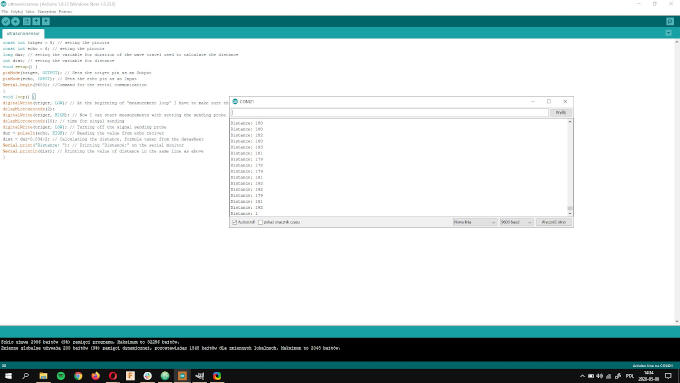

Operation of the sensor on video:
Making the PCB Board
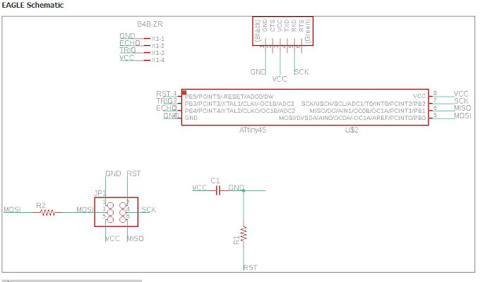
I made the design of the board in Eagle.The board will operate on ATtiny44 and will use the Ultrasonic Distance Sensor HC-SR04 as the example above.
Eagle scheme:
Eagle board:
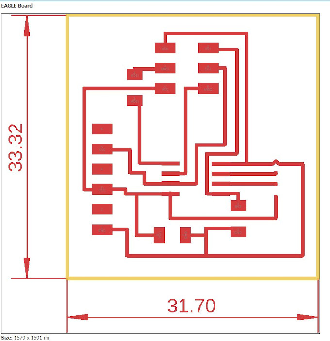
After designing the board I export all necessary files like traces and outer frame of the board to mill it.