Week 07:Computer-controlled Machining
Individual Assignment:
* Make something big (on a CNC machine).
Group Assignment:
* Test runout, alignment, speeds, feeds, and toolpaths for your machine.
Group Assignment
Use the test equipment in your lab to observe the operation of a microcontroller circuit board.Link for group assigment on Maciej Naskręt Page: Week 07 Group Assigment
Individual Assigment
Desiging phase
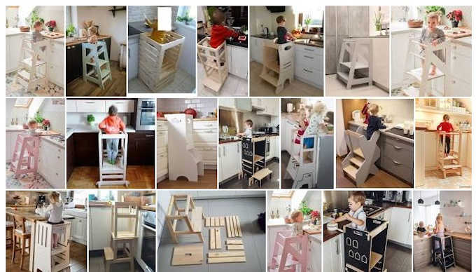
I decided to take this opportunity and finally make a "kitchen helper" for my son, that my wife asked me for many many many months ago.
I begined with look on the Google images for inspiration.
Right after that I can start designing. I used Fusion 360 since it is the software that I know the most and I can directly use it to create the gcode for the CNC milling machine.
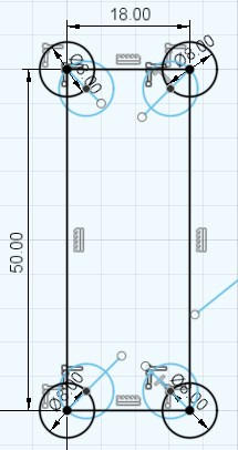
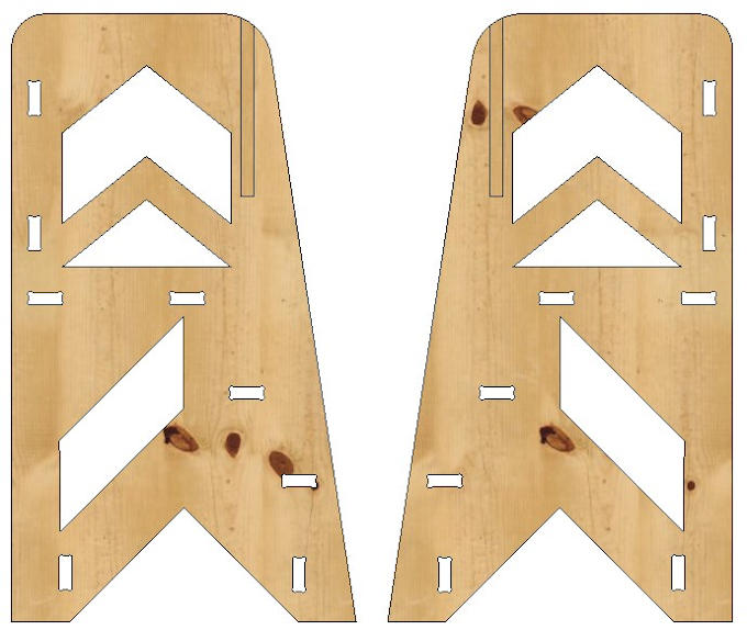
I started with one side. Added some geometrical shapes and dogbones for press fit connection and one pocket for slide-able back panel.
Dogbone design. Dogbones have 8 mm radius.
Left side shows the sketch and right side shows the part extruded for 18 mm.

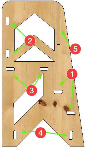
1 - steps
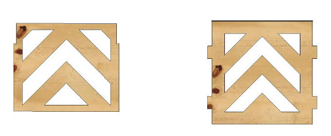
2 - front panel
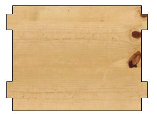
3 - standing platform
4 - vertical bars
5 - slide-in back panel
The previously made side will be mirrored at the end.
Next, I made steps so Miłosz (my son) can climb to the top of the helper. To make designing process easier and faster I used the design of steps as a vertical bars that make the construction stiffer.
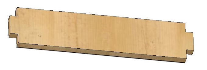
Next I made the front panel and the back panel.
And the standing platform.
Last thing in designing phase is to mirror the 1st side to get the 2nd one with low effort.
Now everything is ready for manufacturing.
Toolpath generation phase
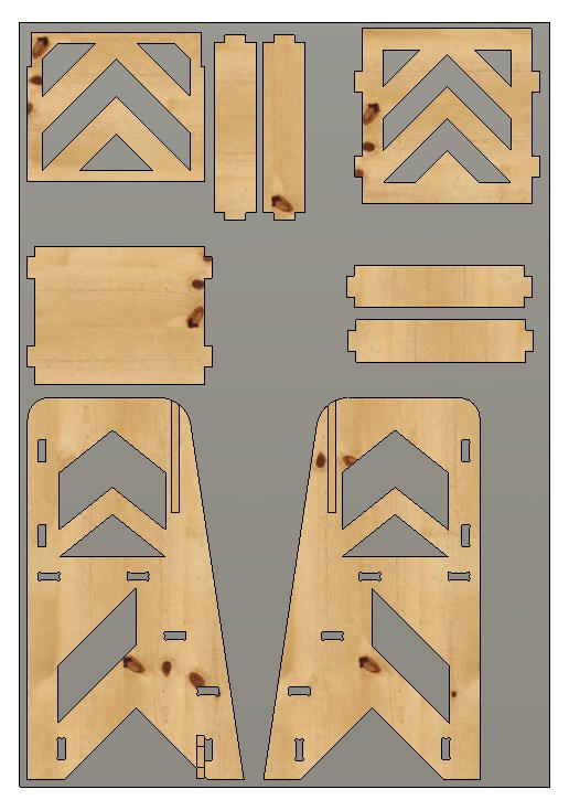
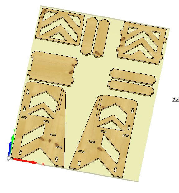
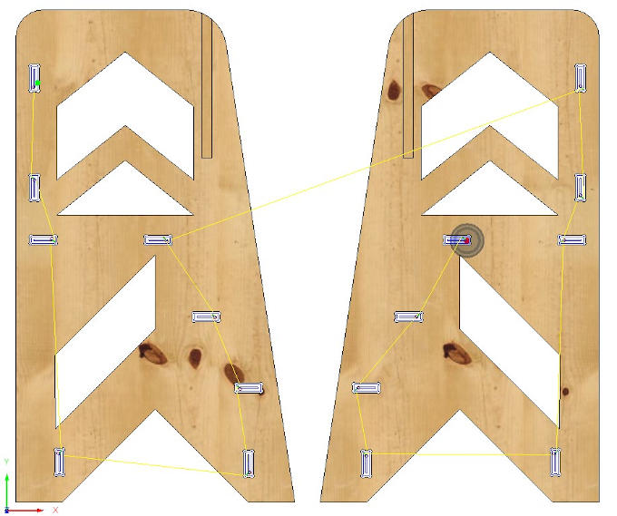
I will create the code for CNC milling machine also inside the Fusion 360 software. Good thing to start with is to make a object that will be in the exact dimensions as the piece of material that I will cut to get the pieces of the designed project. On the following picture we can see the designed parts placed on the gray rectangle, which represents the material for milling.
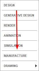
Now I can change from "Design" workspace to "Manufacture".
In this workspace I set all the CNC milling process parameters, like used tools, speeds and feeds or stock size and paths of the tools.
Lets start with the stock.
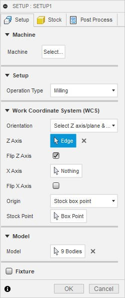
To set the stock I need to use "Setup" fuction
 .
.1st thing to do there is to set the coordination system correctly. As I am using our big CNC milling machine I want to have my Y axis on the longer side and X on the shorter side of the design (and Z as height of course).
To achive that easily I can use features from "Setup" menu.
Next I change the tab to "Stock". There I set the "Stock" which is basically the virtual representation of the material that I will work on to cut out the design.
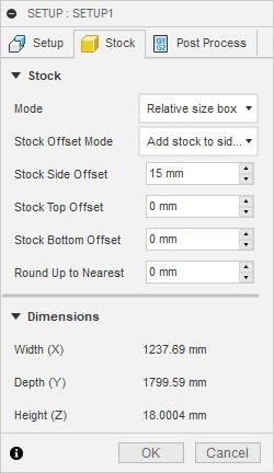
To make sure that tool will be able to move everywhere and all the shapes will be cut properly I had to add a "Stock Side Offset". This value adds additional mm to the sides of the automatically generated "material".
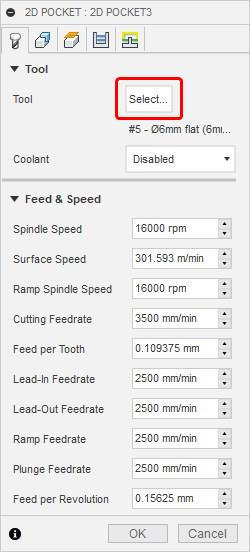
1st operation that I will apply will be 2D pocket for slide-in back panel.
But before I do it I have to add new tool 1st. I can do that after choosing "2D Pocket" from "2D" operations and "Select" button in new window.
Then "Add tool".
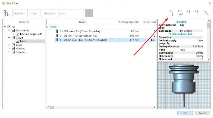
And I have to put all the tool parameters. To get them I have to 1st physically measure the tool with use of caliper.
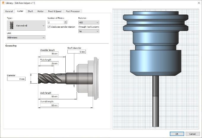
Now I accept the changes and select the tool for this opperation.
After coming back to the 2D pocket menu I change the tab to 2nd one which is "Geometry", have I select the places where the fuction will be applied.

Next tab that I made changes in is "Passes". Here we can ,for example, set what is the maximal step which is basically a maximal value how deep the tool can go at once or the direction of cutting.
I will set the "Maximal Roughing Stepdown" to 5 mm as I was advised by our CNC Milling expert. So the tab looks as following:

After this I accept all settings by pressing "OK" and the software will take few moments to calculate the path of tool for this opperation.

Next step was to make path for all dogbones, as advised I used also 2D contur for those. Using this method for those small parts, insted of 2D contour, is to prevent small leftover parts from damaging the machine. Since they could be ripped away. 2D Pocket will mill everything inside the dogbone leaving nothing inside. I will use the same tool and the same settings as the operation before. Only difference is that I will chose dogbones instead of designed slots.
Result:
Blue lines inside the dogbones are the paths for the tool while it is milling and yellow ones are the travel path while the tools is not milling the material.
Next up is 2D Contour for the inside elements. This time also I will use 6 mm bit that I used for previous operations. In this operation I will just choose the contours of the parts that are inside. The most important trick is to remember to choose the contours that are on the bottom side of the design.
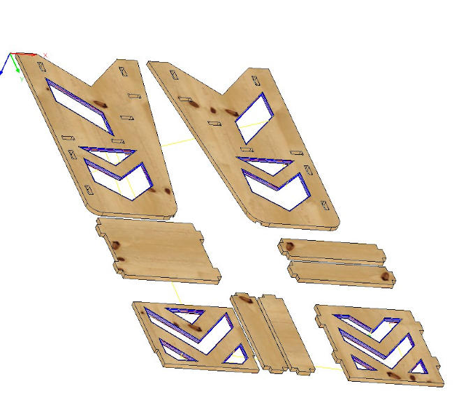
View from the bottom of the project.
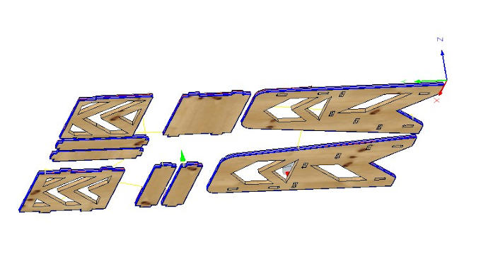
Now I have to do the same operation but for the outer contours.
Now when all paths are ready all is left is to save the NC file and go to the machine.
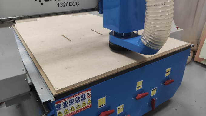
Milling phase
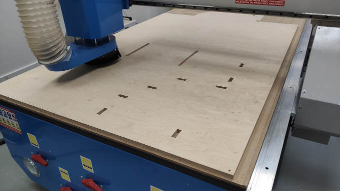
Now when necessary file is on the machine I have to bring the material and place it on the machine's working area. To make sure it will not move during the milling operation it have to be secured will wood screws to the working bed. After placing and securing the material, the machine can be turned ON. Before running the file with tool path I have to position the miling tool. The place have to be the same as I set in the software since all path are caluclated with the refferance to this point. If this is set I can run the milling.
Right away the machine start to mill the pockets as programed.
And dogbones:
Inner contours:

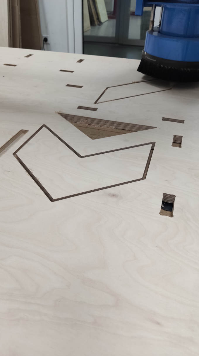
And finally outer contours:
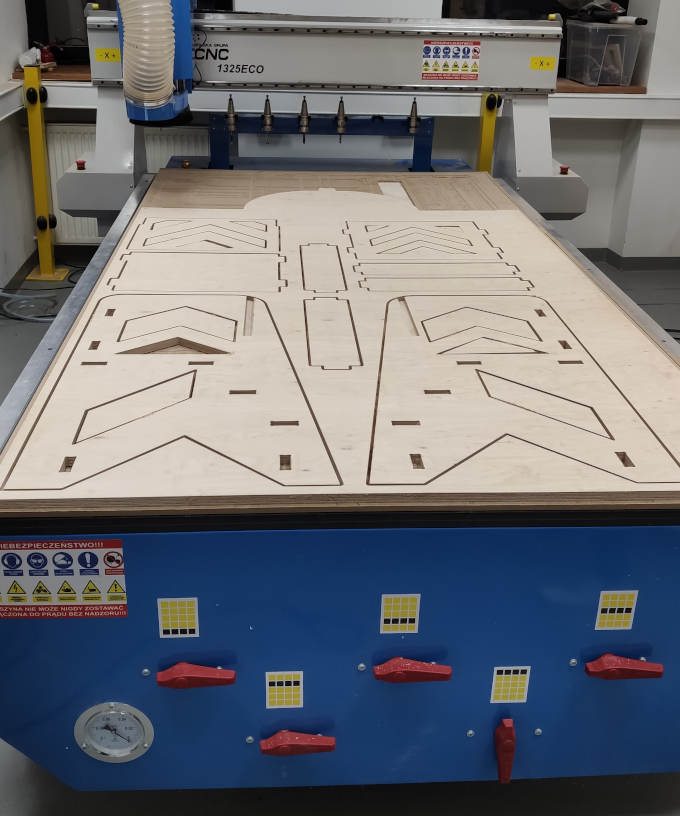
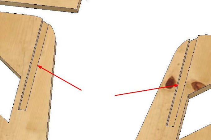
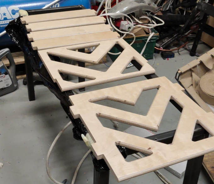
Now when the design is milled it can be taken out and tested if everything fits.
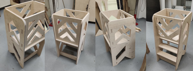
Fits like a glove!
Now wood needs to be processed to make it safe for kids.
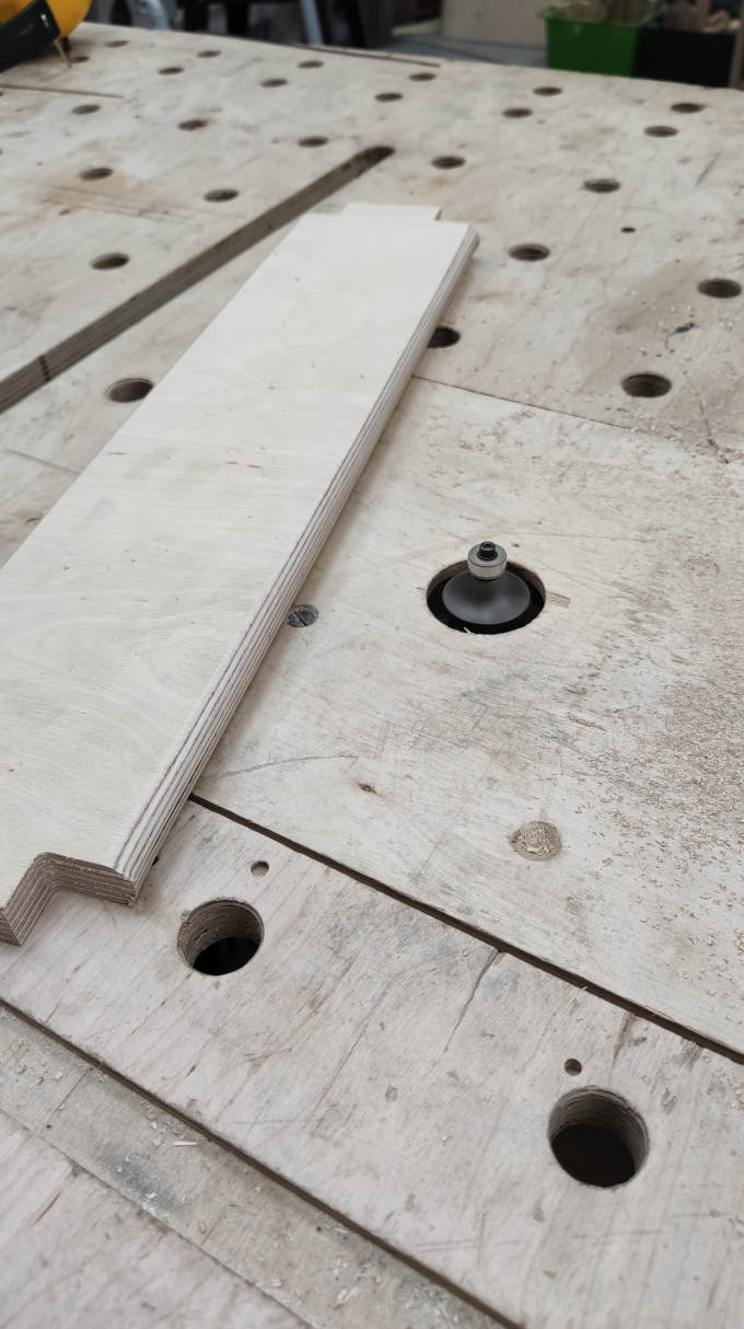
1st thing is to filet all the eadges to make them nice and round. At this point I finally learned by hearth that the piece should be moved against the rottary movement of the rottor with fileting bit.
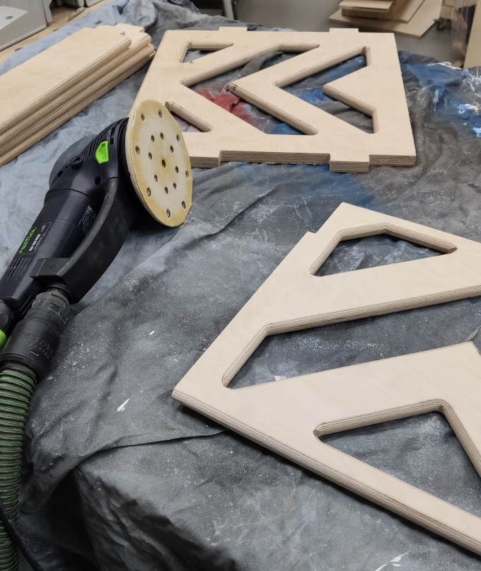
Now sanding, to make the wood soft and to get rid of all possibe splinters.
After proper sanding it is time to laquer the pieces to protect them from dirt and damages.
I will put 3 layers of laquer, after each layer is dry I have to sand the surface gently to get rid of raised wood fibers. When the whole process is done the parts are ready to be assambled and used :)

Go back to front page Go back to Week 06 To Week 08