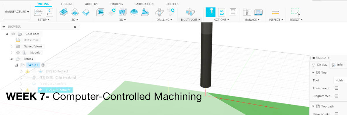
Week_7 - Computer-Controlled Machining
Assigment
- group assignment:
- test runout,
- alignment,
- speeds, feeds, and toolpaths for your machine
- individual assignment:
- make (design+mill+assemble) something big
Group Assignment
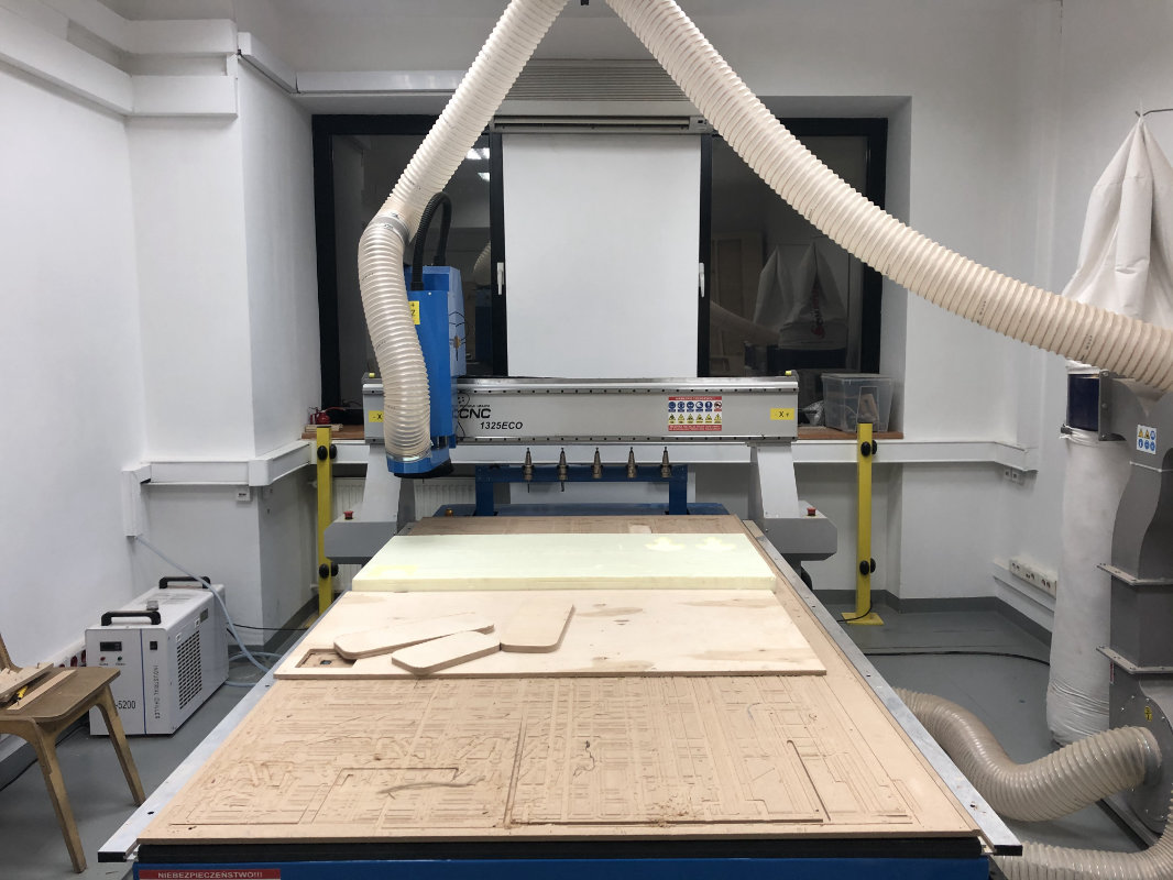
A few words about our milling machine:
the tool wall at our cnc workshop is very useful for organizing tools
Preparation of tools in Fusion 360
Preparation of the tool makes it very easy to get the data sheets of the cutter from the distributor, or to check the auction or basic data in the online store.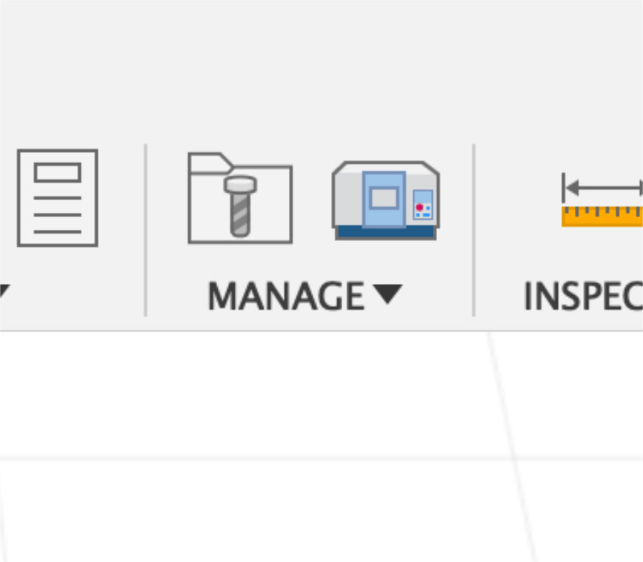
As a program to create files for milling I use Fusion 360 CAM module. First it adds new tools to my accounts by entering the CAM TOOL LIBERARY icon.
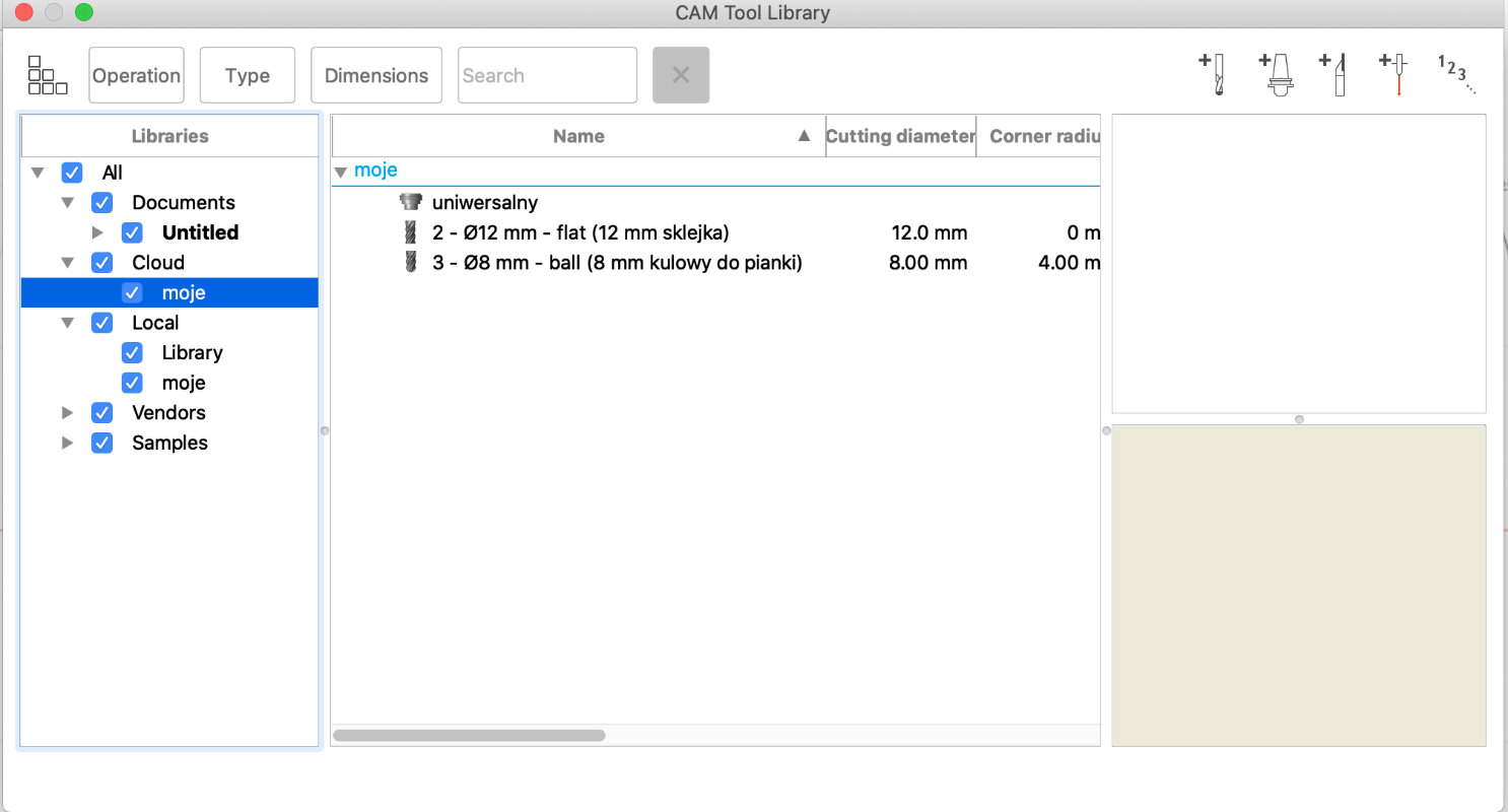
In cloud TAB we add a new folder for our tools which will be available from any computer.
On the right side we click add milling
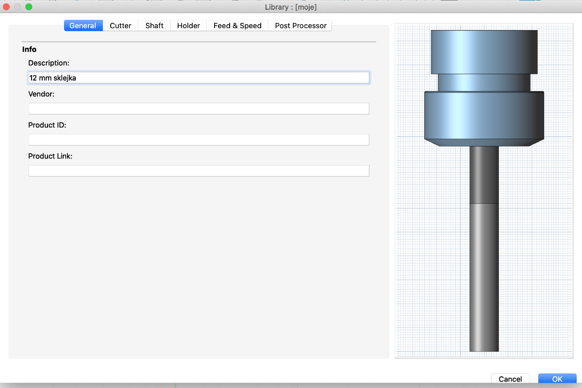
We name the cutter
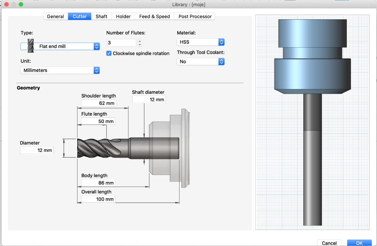
We provide basic data
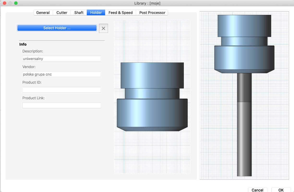
its good to preper a holder before we start to add tools
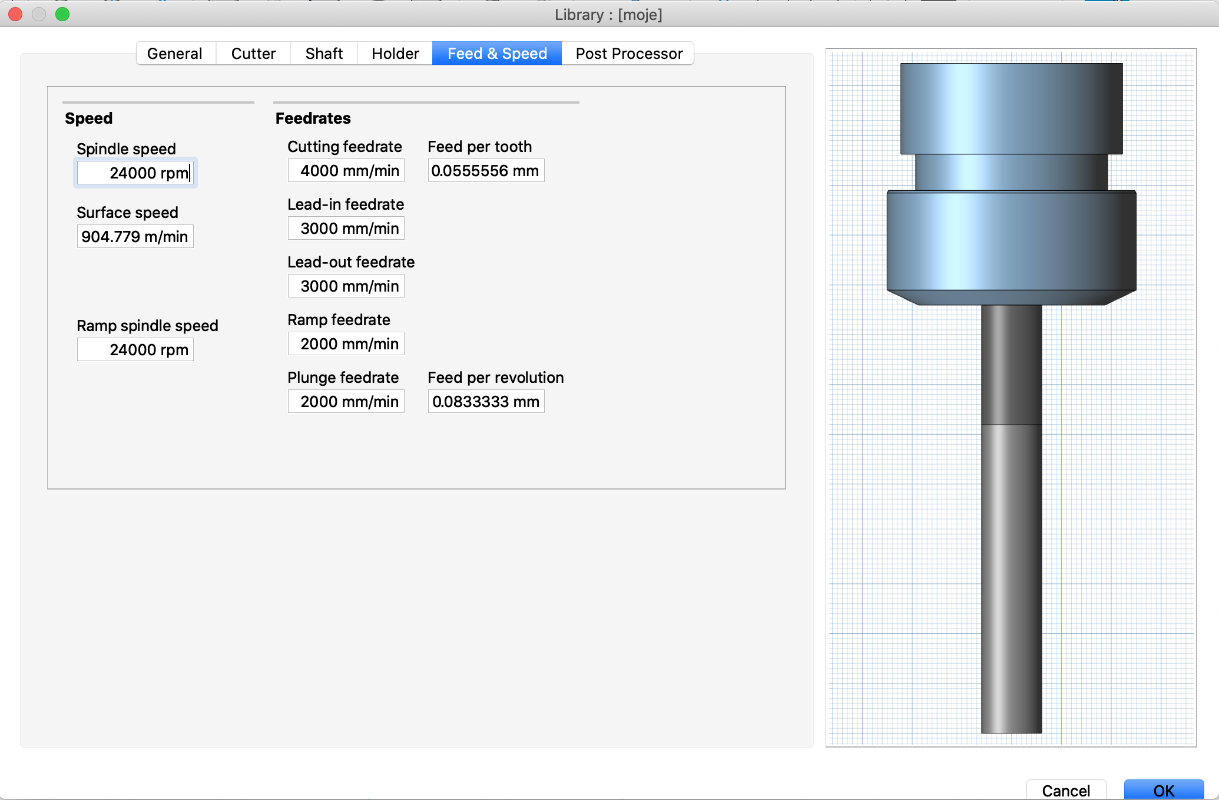
feed&speed
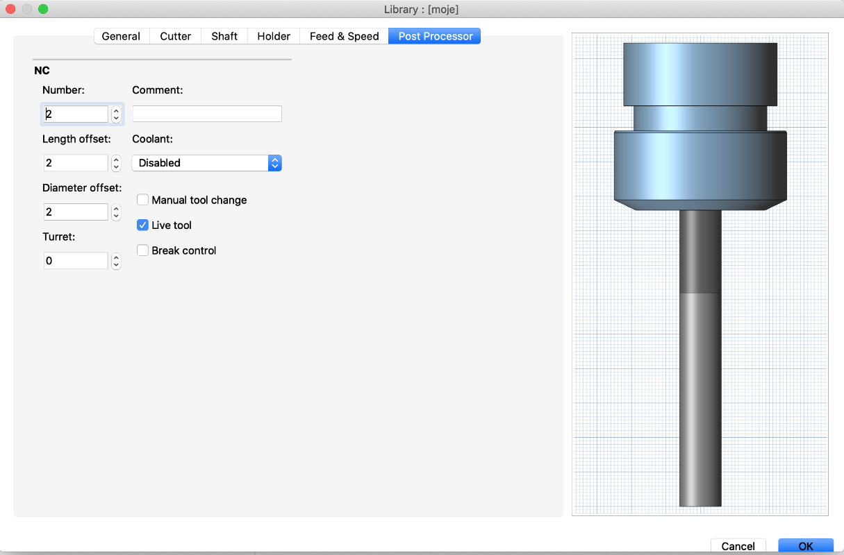
Then we have to add the number of the tool we are using on cnc machine and whether we will use cooling and if so, what kind.
individual assignment:
Modeling for cnc milling
I have to write here that I like to design for a cnc
milling machine because at the end product is usually
large and almost immediately ready for use.
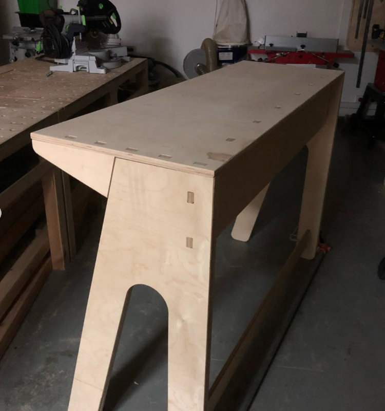
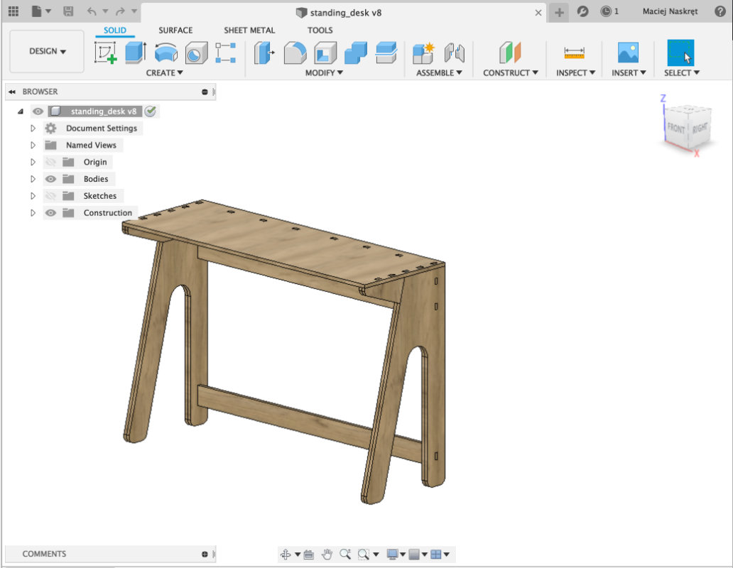
Below is one of the last projects I have done,
a standing desk inspired by the furnitures that
are in fablab.
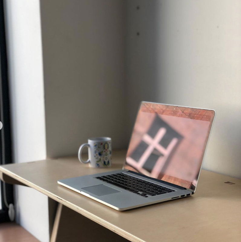
Standing desk became very much needed when fablab
suddenly had a lot of people working on 3d printers,
sometimes bumping into it for literally 10 minutes
to prepare and start printing. I checked the
anthropometric boards for the height and started
designing. The result below.
Designing 3d model in Fusion 360
I always start the design process by collecting information on a given topic, collecting information on similar products, searching through the pinterest to find something new to apply in my project.
Also very useful are anthropometric tables and drawings showing the most ergonomic position of a person at a given device.
I determined the height of the table and the appearance of the project based on the collected information. I was thinking about adding shelves under the table top and a holder for the extension cord at the back but on the other hand I thought it would be better to keep it simple.
Below is the design process in fusion 360.
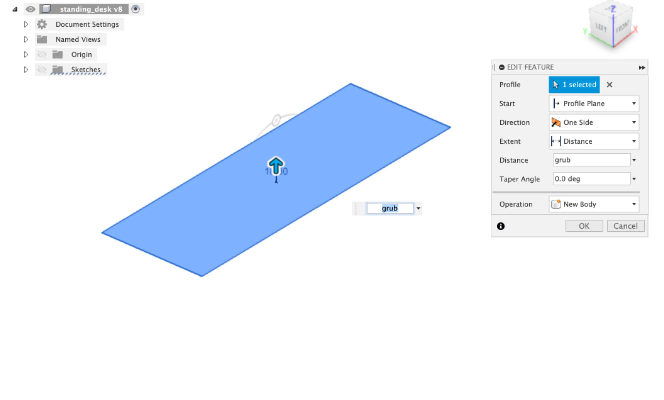
extruding the table top form rectencular sketch
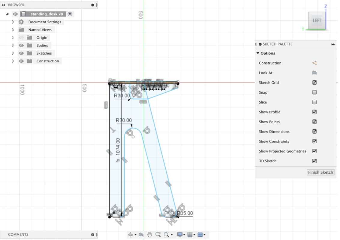
sketching table legs using lines, polilines and filets
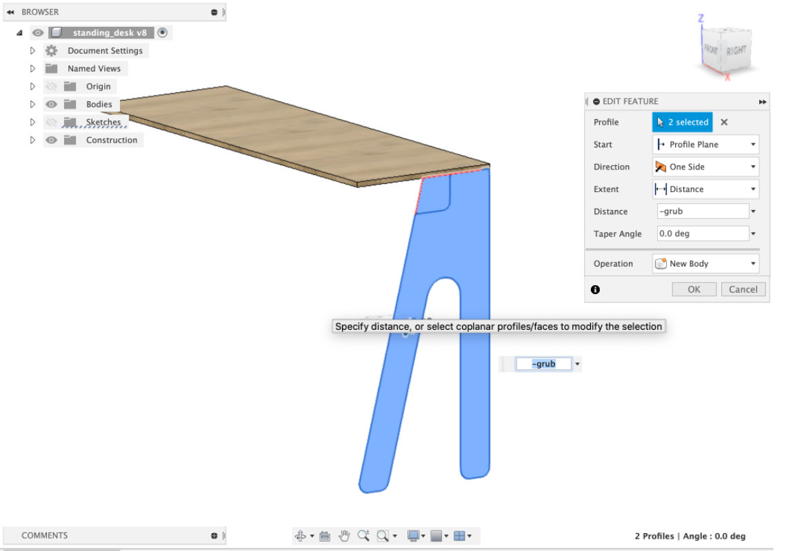
extruding table legs form sketch
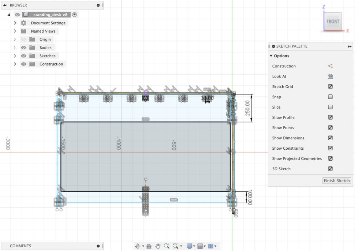
sketching apron and stratcher for making the structure more solid
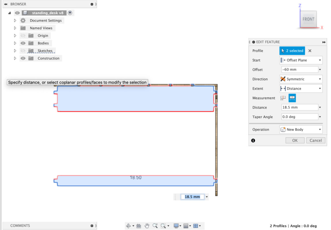
extruding apron and stratcher symetricly
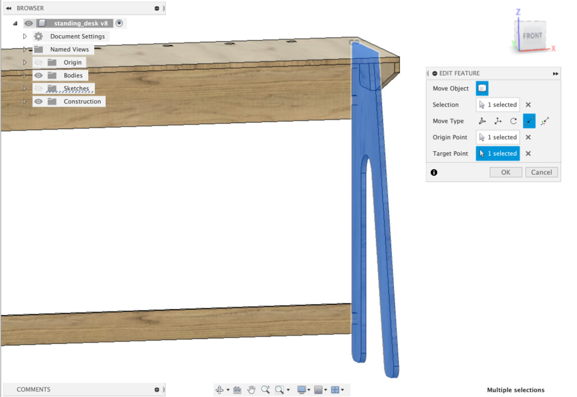
adding one thikness by adding one more leg for a site
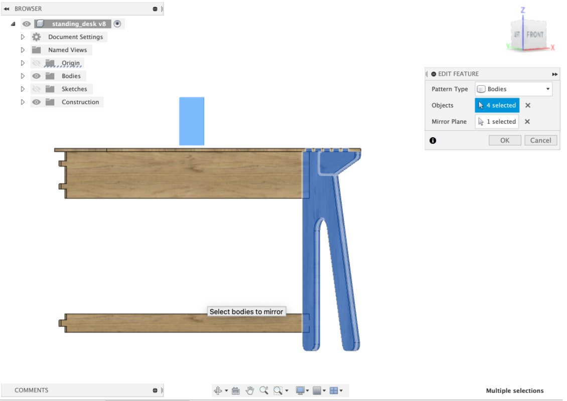
mirroring legs for the other site
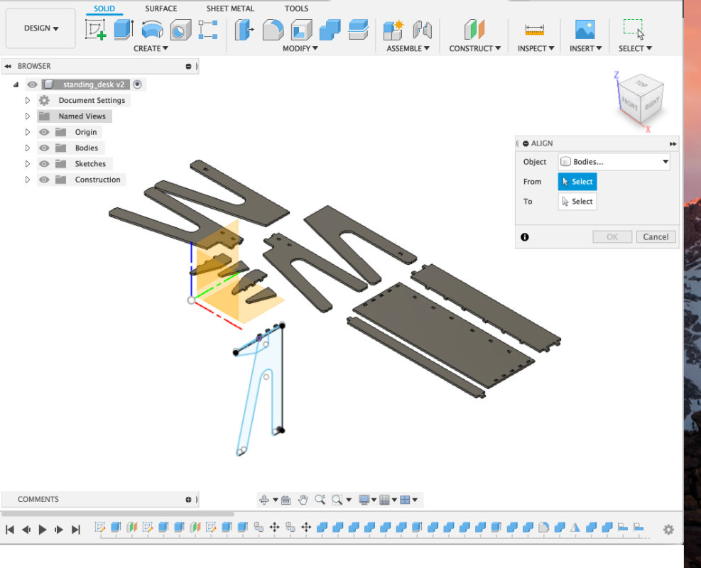
Remeber always to use align before going to Manufacture in fusion 360.
I always save the version before that and name it xxx_before_align.
File Preperation for milling
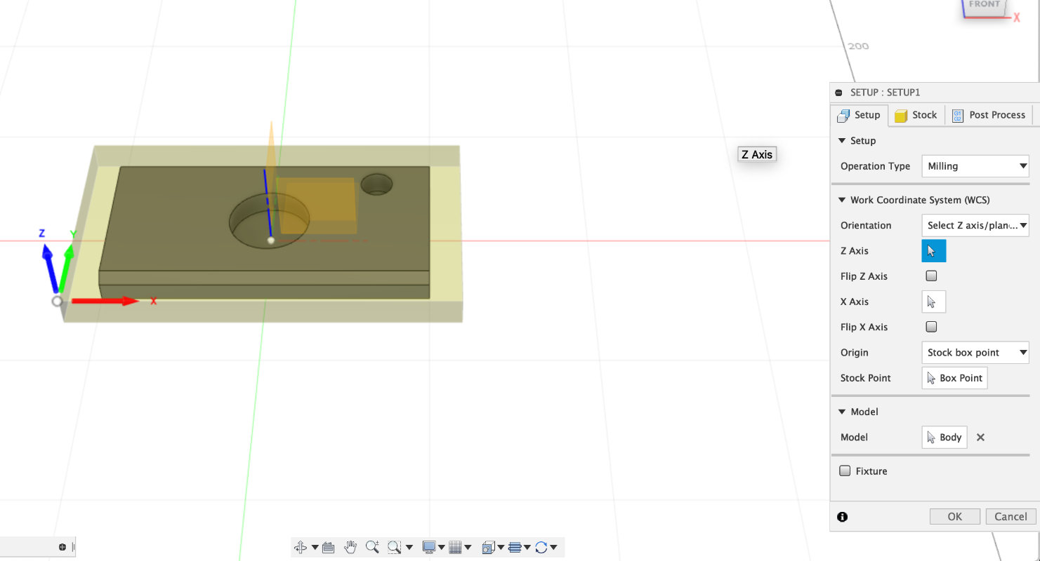
It is always a good idea to start setting up a file by preparing the workspace and setting up the setup.With WCS (work coordinate system) we can choose several options I usually use two with the use of the Model object or without selecting objects, simply all the objects in the project. Sometimes I also create a body which is the size of the material I will use for milling. Then using Orientation =>Select With axis... I set up the axes and with the stock point it indicates the top point of the material.
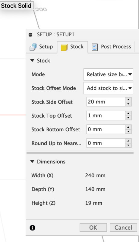
 In stock tab I set relative size box and give offset
(in case when in the first tab I didn't choose previously
prepared body in model)
In stock tab I set relative size box and give offset
(in case when in the first tab I didn't choose previously
prepared body in model)
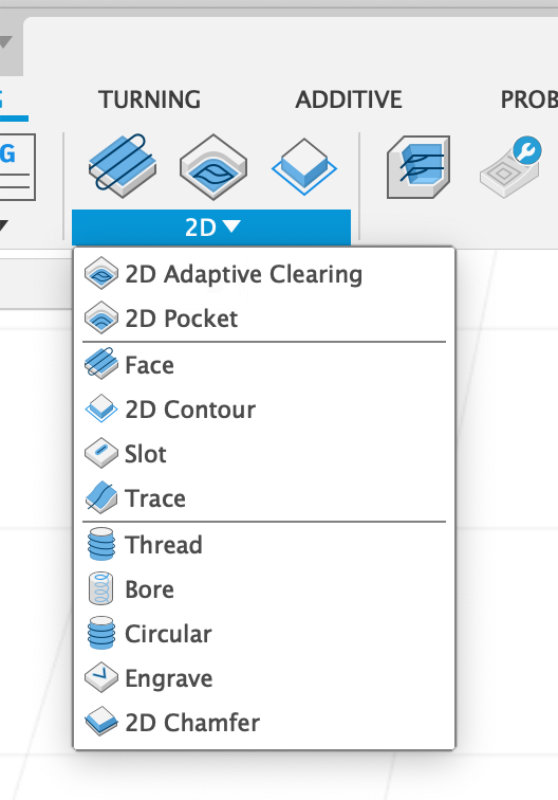 All fusion basics cam machining tools can be found in the Milling 2D tab.
Among the many options we will first take care of the 2d pocket. This is a tool that allows you to cut the selected pocket with the bit.
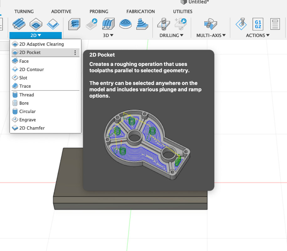
All fusion basics cam machining tools can be found in the Milling 2D tab.
Among the many options we will first take care of the 2d pocket. This is a tool that allows you to cut the selected pocket with the bit.
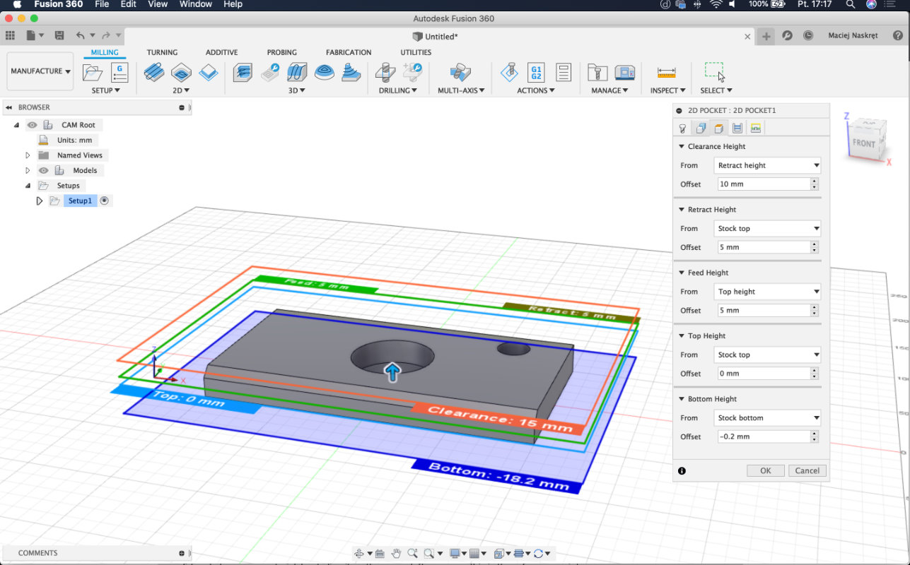
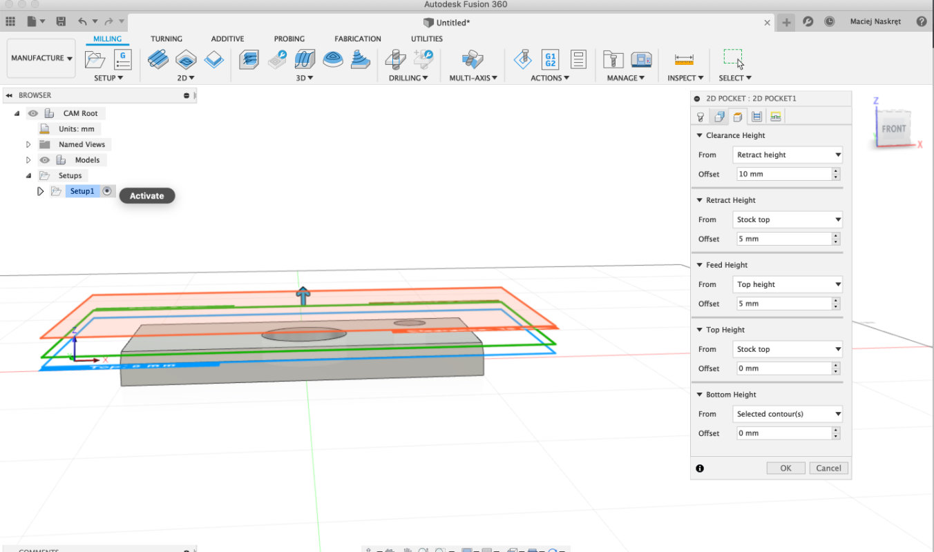 A new 2d pocket panel appears, in which we set all parameters
 I set:
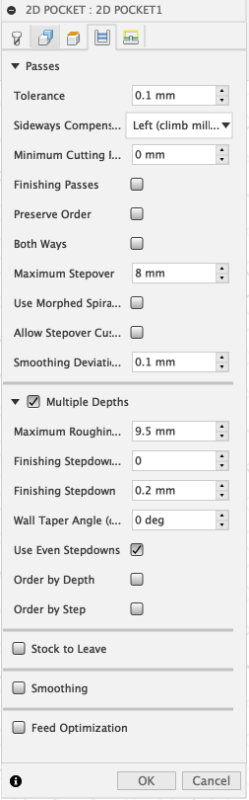 Passes
In this section, the important laws are:
Passes
In this section, the important laws are:
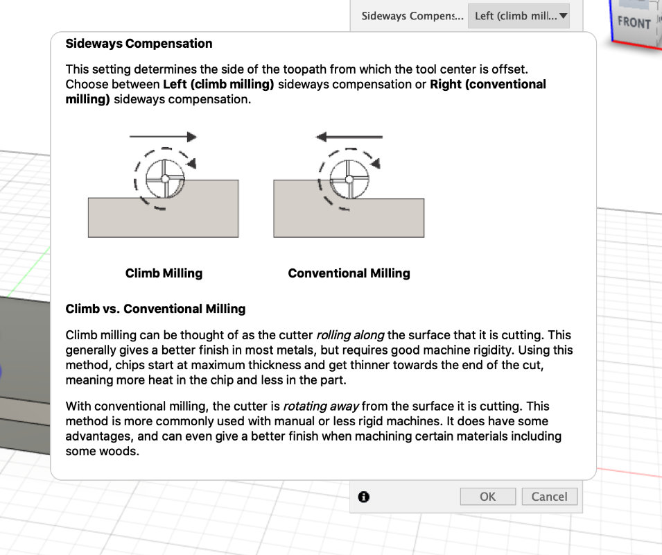 We can also set whether we're going to mill the climb or conventional. (depends on the bit)
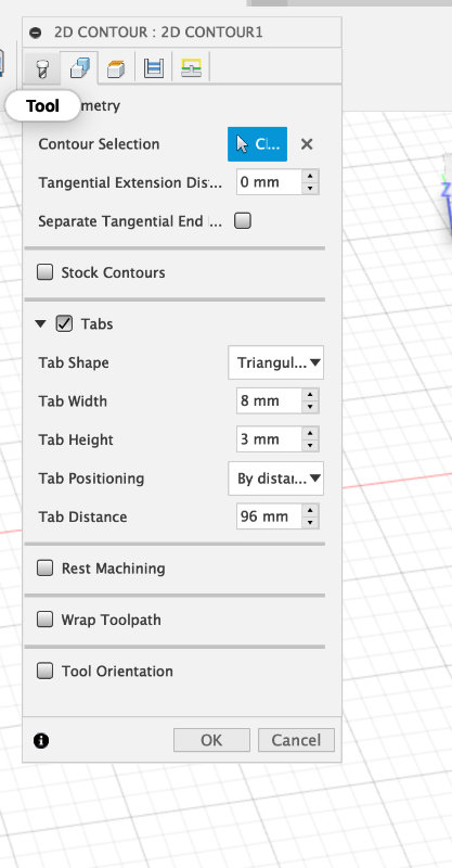 The next funk is the 2d Contur, which allows us to cut out the line.
We choose contour. We can also set Tabs, which are places where
the program will design bridges so that the cut out element will
be still connected to the whole board. This allows us to repeatedly
avoid the problem with flying parts:)
The next funk is the 2d Contur, which allows us to cut out the line.
We choose contour. We can also set Tabs, which are places where
the program will design bridges so that the cut out element will
be still connected to the whole board. This allows us to repeatedly
avoid the problem with flying parts:)
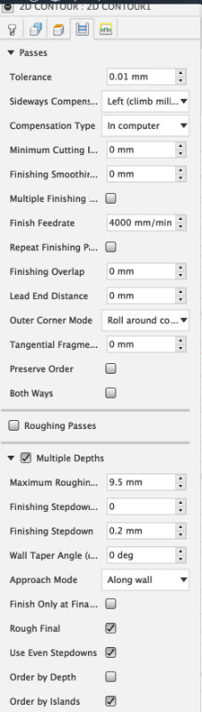
pass settings for cutting through for plywood
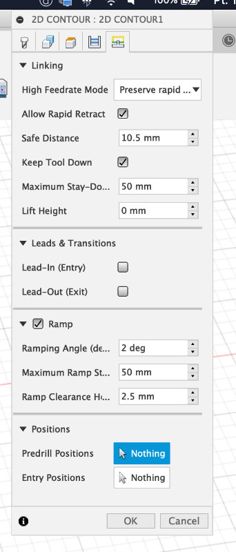 Linking - allows us to set basic milling rules
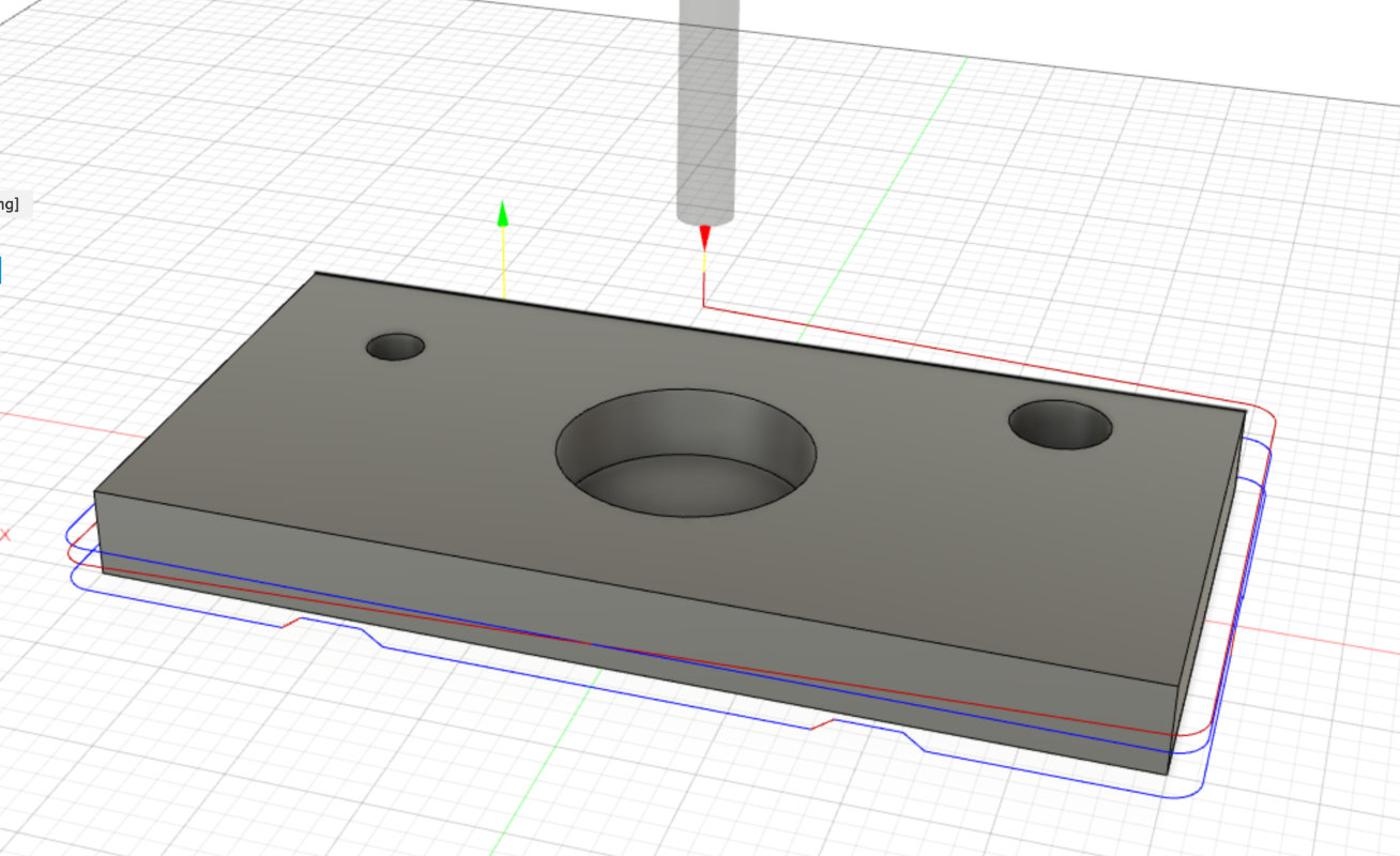 Here you can see the path we i generated for contour cutting.
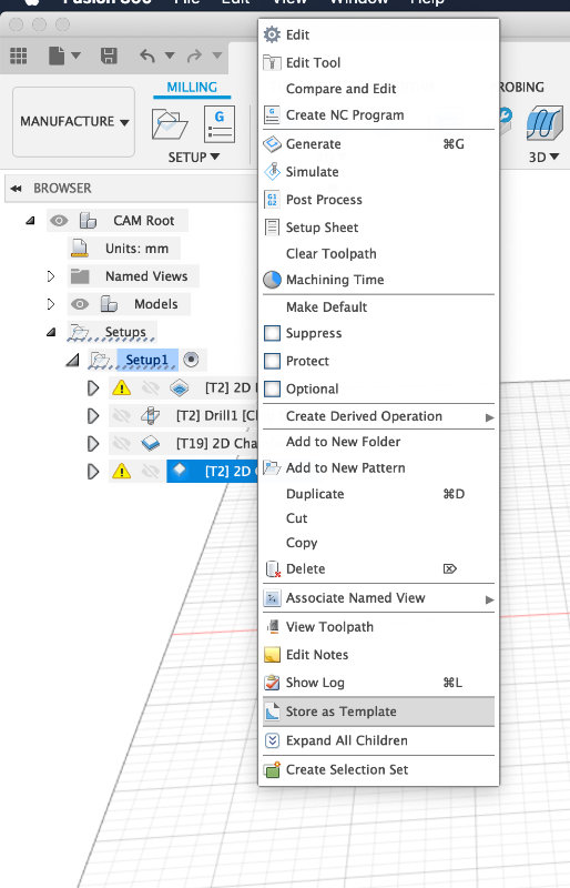 Each executed function can be saved and store in Template which will
allow us to speed up work on the next similar task.
Each executed function can be saved and store in Template which will
allow us to speed up work on the next similar task.
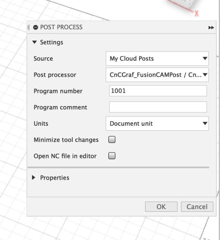
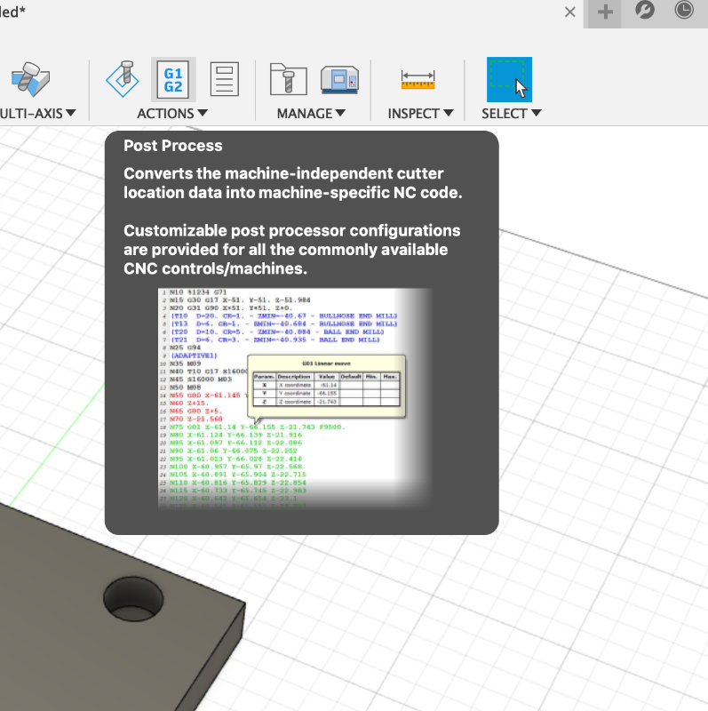 In the Action section we have a Post process where we can add
our own postprocessor or use a ready-made one available on the Internet.
In the Action section we have a Post process where we can add
our own postprocessor or use a ready-made one available on the Internet.
Below is a video of a video showing milling emulation.
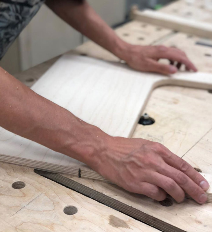
Woodworking!
Finaly i get all the parts milled. And now its time to assemble and i have to be honest it was so easy because every thing assmebled so easy and smooth that i was suprise. I did all the carpentery work with less than an 1h. + a day for painting with few layers.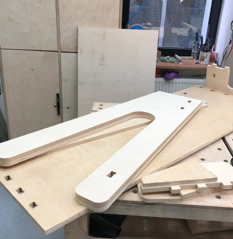
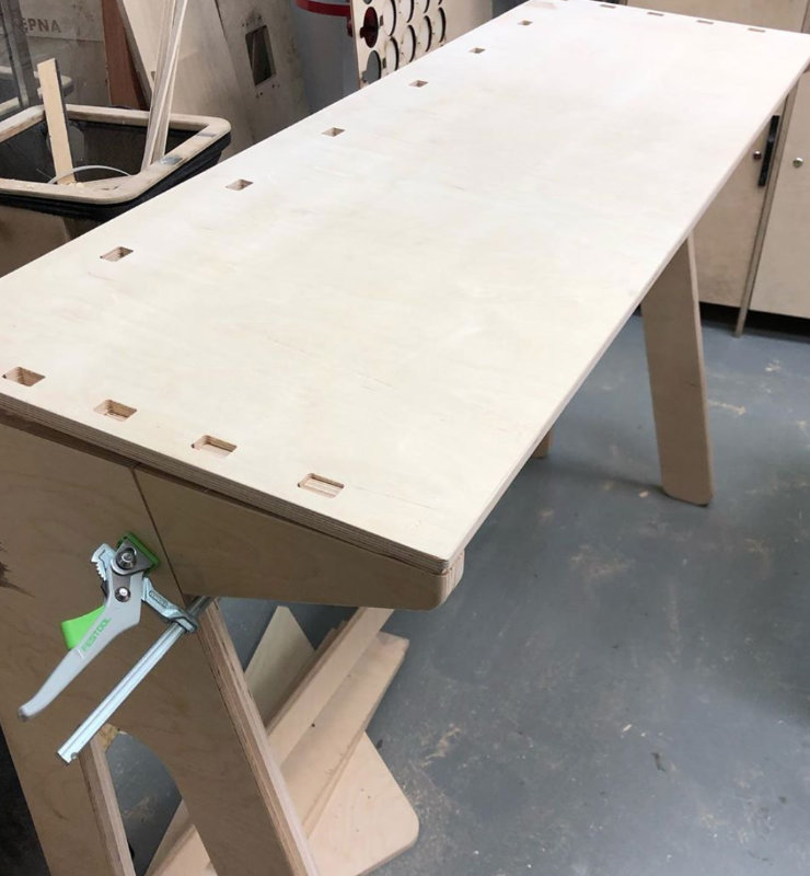
Finaly done!
Now anyone who comes to the Fablab can use this table at 3d printers zone:) Enjoy!