ELECTRONICS DESIGN
This week I worked on redesigning an echo hello-world board, and then added a button and LED; This week I had difficulties completing it due to the context of the covid-19, so the work I do is only digital.
INDIVIDUAL PROJECT
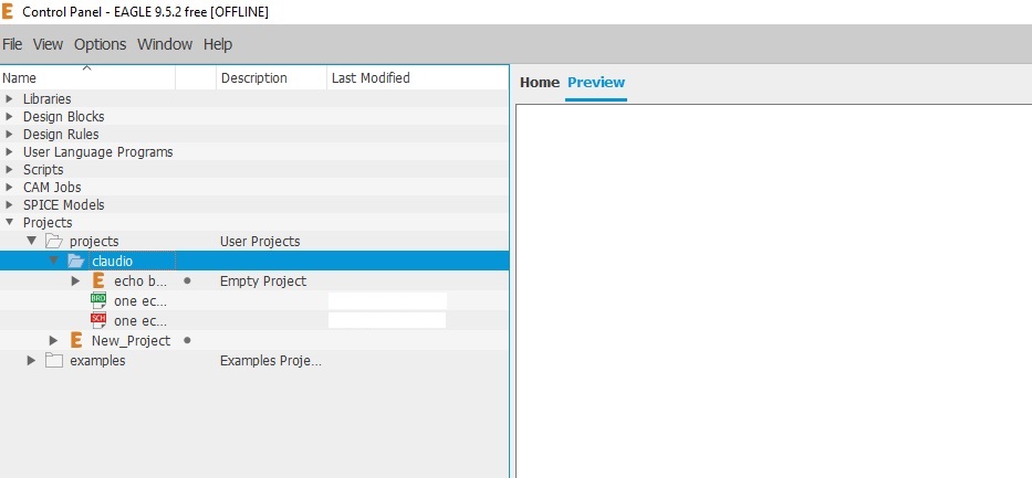
The software I used is EAGLE, where I created my folder and a new file
To carry out the activity, it is necessary to download the library provided by the fab academy, the eagle_lab library, where we will have access to the components most used in the laboratory.
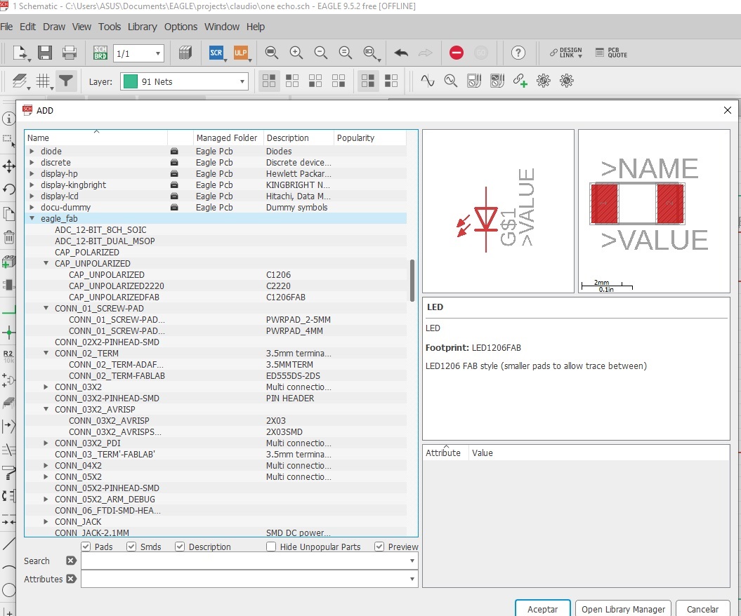
In this working space, we need to select the components for our echo board, using the first image as a guide, so the components are:
ATtiny 44, Resistor 10k, Capacitor 1uF, Resonator 20Mhz, 6x1 FTDI, 2x3 ISP.
And the components to add for the assignment:
Resistor 1k, 1 LED, 1 Button.
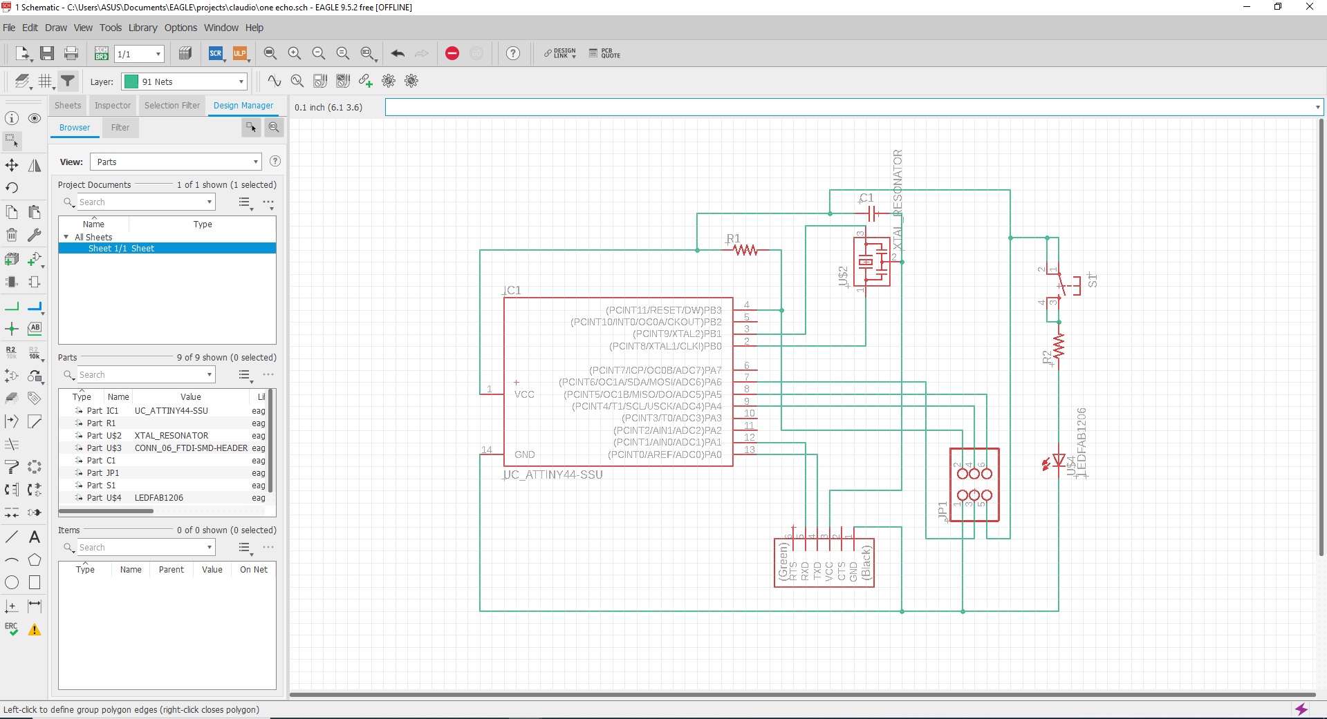
To redraw I chose an echo board based on the ATtiny44.

After performing the redesign, I proceeded to add a button and LED, also taken from the library.
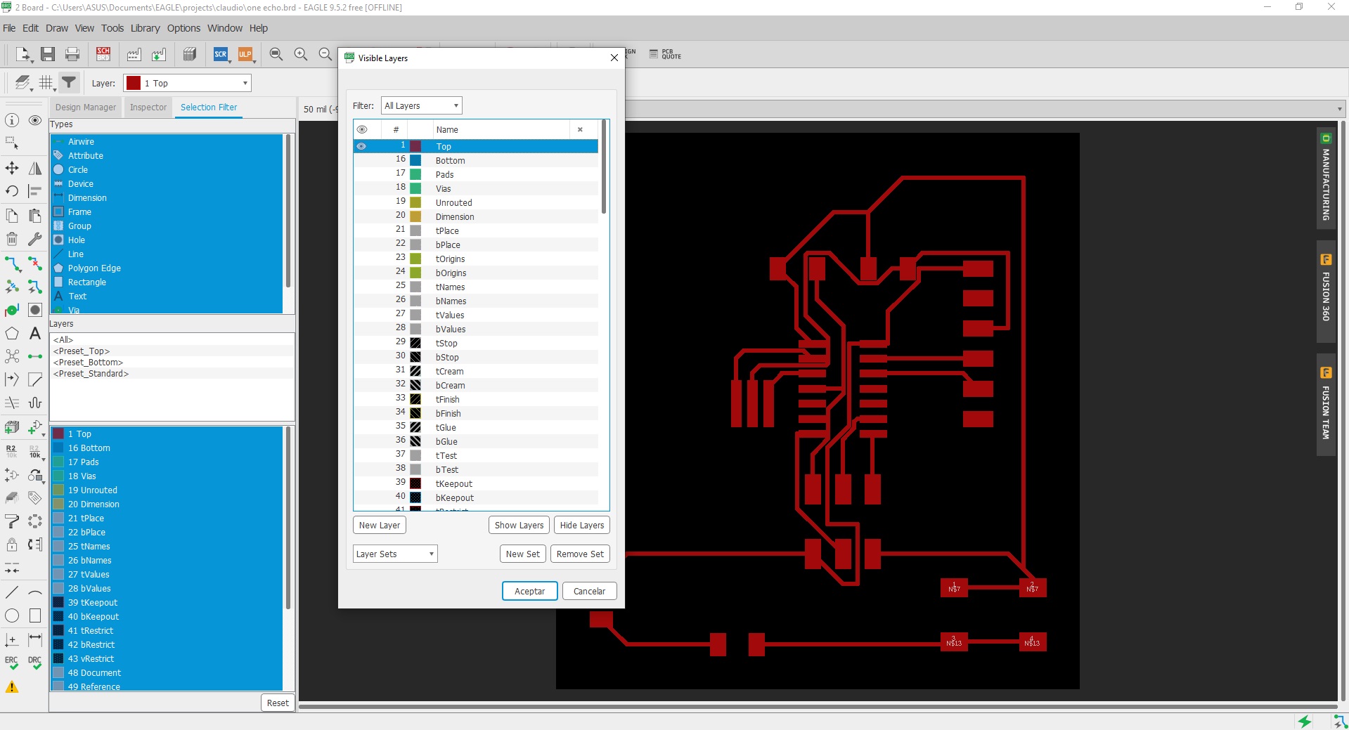
In the PCB view, I used the Route Airwire button to make the traces. To draw the trace wider I modify the parameter from 6 to 12.

Before I can export the circuit to an image format, I need to select the layers I want to be displayed, selecting the top layer, showing the red layer.
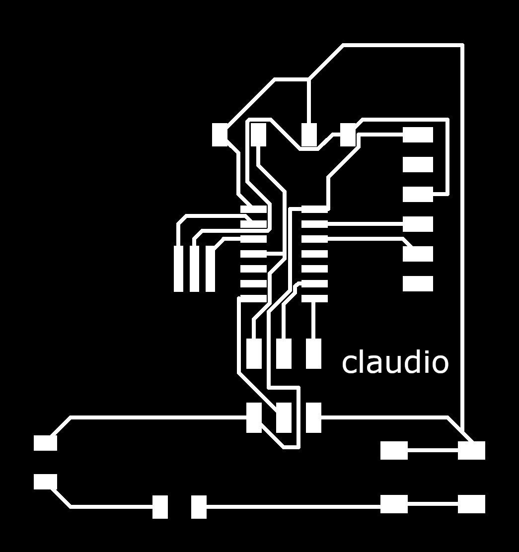
In order to mill, I drew a boot-shaped path and put it on a different layer to differentiate it from the circuit, in addition to exporting the files with the monochrome setting. and a resolution of 600pp.

Then I used the GIMP software to look at the image, where I can make some modifications if I want.
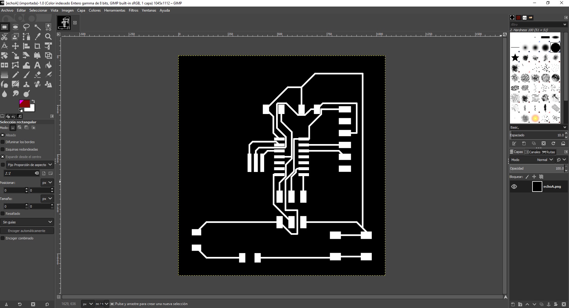
The final .png files look like this
|

|