4. Computer controlled cutting
Files used:
SVG Parametric construction kit - first test
SVG Parametric construction kit
In this week we have a group assignment and individual assignments, and I will start with the first one:
Group assignments:
Laser cutting machine:
Objectives: characterize your laser cutter’s focus, power, speed, rate, kerf, and joint clearance
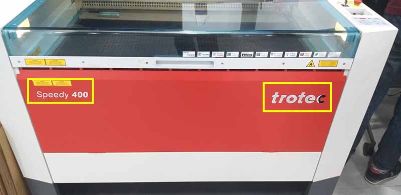
Machine used: Trotec Speedy Laser Engravers; Speedy 400.
Data sheet: Speedy 400.
Laser Software: Jobcontrol.
Before using any machine in general you should read the data sheet before operating, as well as read the safety sings for your protection and others.
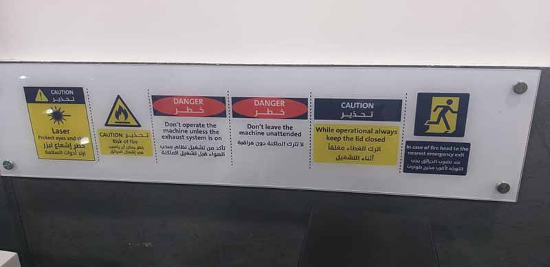
Safety rules and warnings: - Protect eyes and skin by wearing the proper safety glasses. - Risk of fire. - Don’t operate the machine unless the exhaust system is on. - Don’t leave the machine unattended. - While operational always keep the lid closed. - In case of fire, head to the nearest emergency exit.
Turning On the machine:
When turning on the machine, it will start calibrate to its zero offsets, the first one id done automatically to the bed until it reaches the maximum bottom.
After that, we press the two buttons UP and DOWN simultaneously for two seconds, the Laser head will move to the top right corner to calibrate X axis and Y axis.
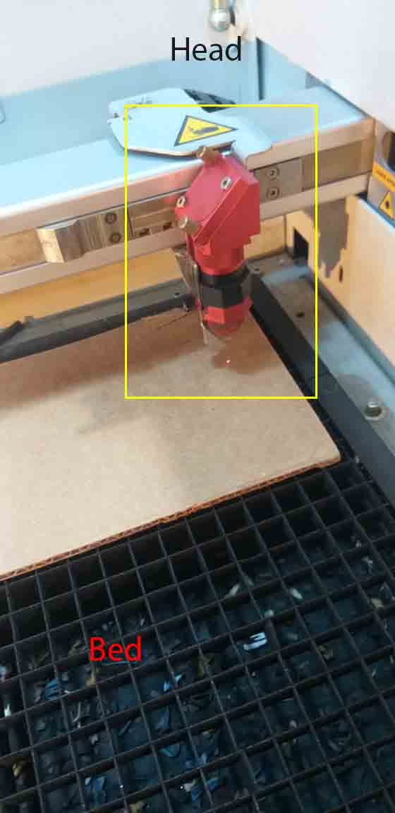
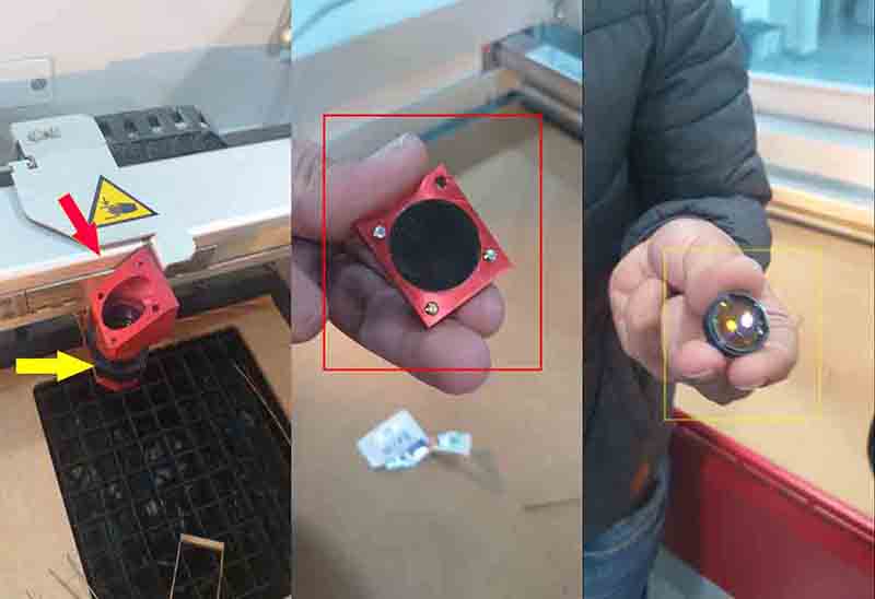
Maintain Laser head:
We check on the laser head, where the laser hits a mirror inside the head and reflect it to the lens, and make sure they are clean.
Red for mirror, and yellow for lens.
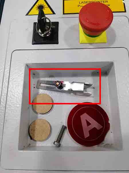
Adjust the Laser head:
After putting the piece that we want to cut, we adjust the head height by attaching the Focus Tool to the laser head in the working area, then press down until the Focus Tool hit the surface or barely detached from the laser head.
2D design and Cutting:
Kerf test:
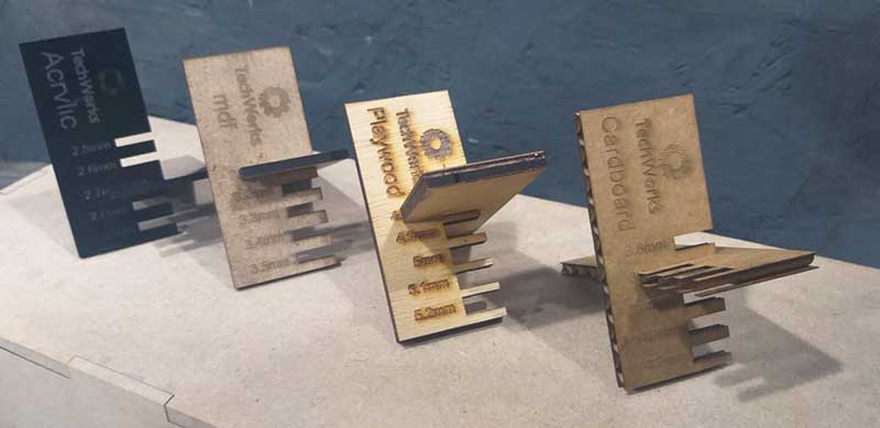
For the kerf test we used this design and cut it twice to see which one holds nicely, by making a press-fit joints with ±0.1mm step from the thickness of the material.
Where in this laser machine red RGB (255,0,0) is for cut, and black (0,0,0) is for engrave.
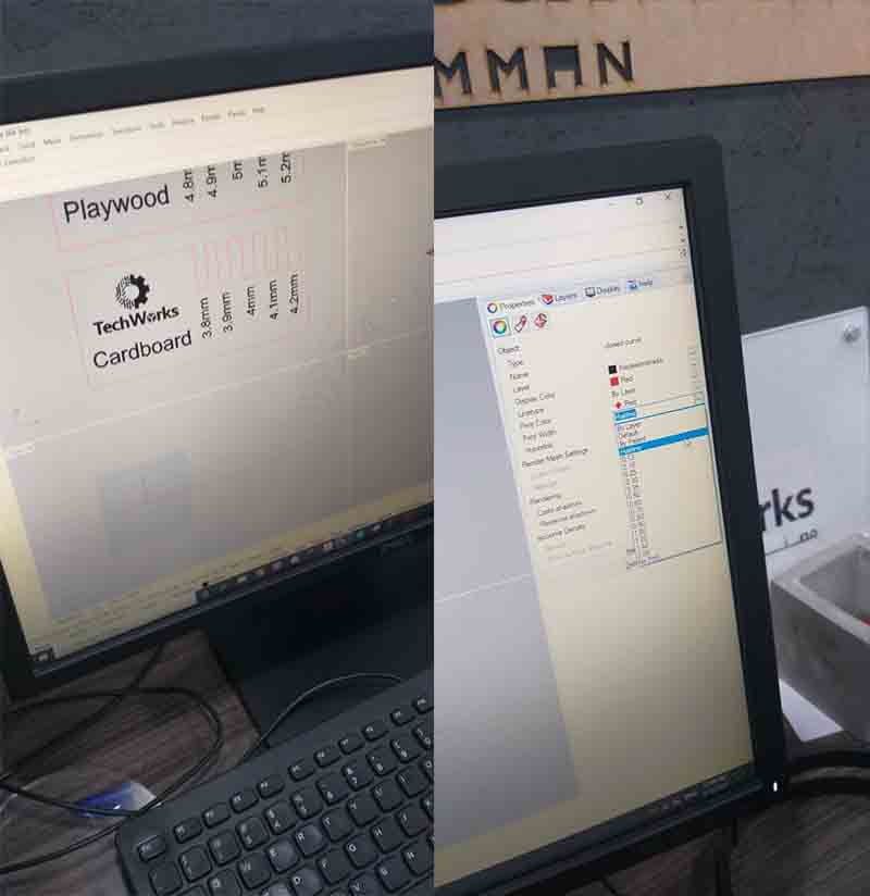
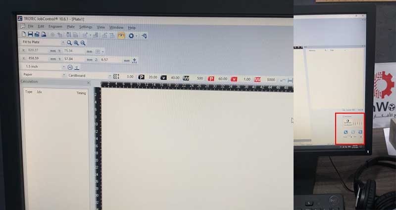
By selecting the wanted test cut, we select the print like a normal printer, but when we click on properties, it will prompt a window to the machine’s program Jobcontrol.
We select from the material settings for example:
Paper

Carboard
and the process options keep it standard, then hit the Jobcontrol’s logo to export it to Jobcontrol software.
Then we move the kerf test cut to snap to laser’s head location, which gets updated in the program.
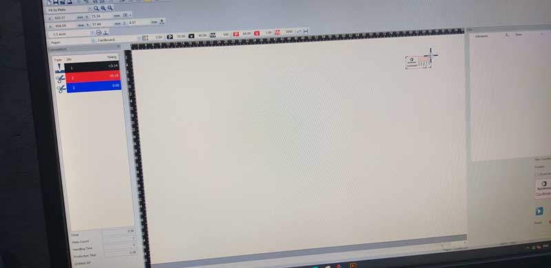
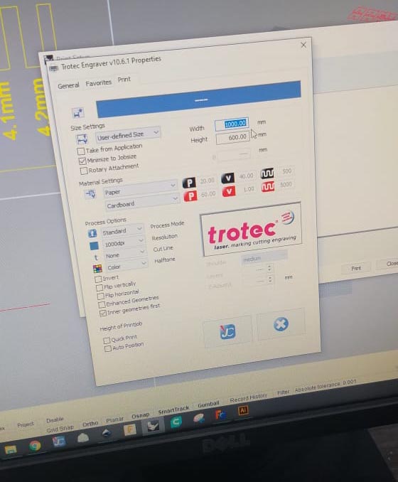
We used the default settings to cut the Kerf test board, and the setting was for the machine:
Engrave:
Power: 20%, Speed: 40%, and frequency: 500

Cut:
Power: 60%, Speed: 01%, and frequency: 5000
But we change the Engrave settings to:
power: 20% to 40%
And the output was for the next materials
Carboard: thickness 4mm, kerf : 3.9mm

MDF: thickness 3.3mm, kerf : 3.0mm

Acrylic: thickness 2.7mm, kerf : 2.7mm

Plywood: thickness 5mm, kerf : 4.8mm
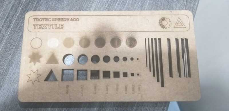
Engraving test:
We used this template to test out the engraving and cutting and linear engraving.
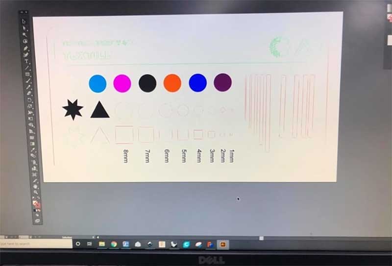
And the following was manually inputted to the program, where Green for linear engraving and it was similar to the cutting setting but with more speed, where the circles from left to right have incremental percentage in power for rastering/ engraving, and red is for cutting.
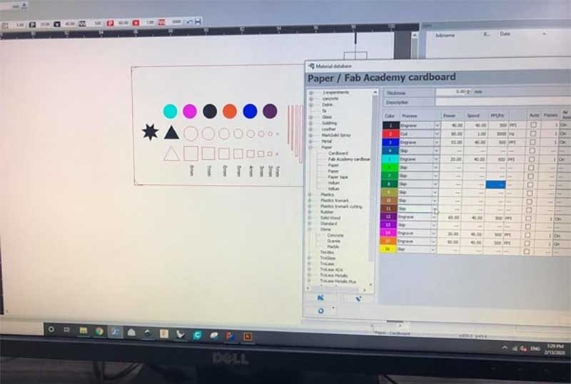
From left to right:
20%, 30%, 40%, 50%, 55%, 60%
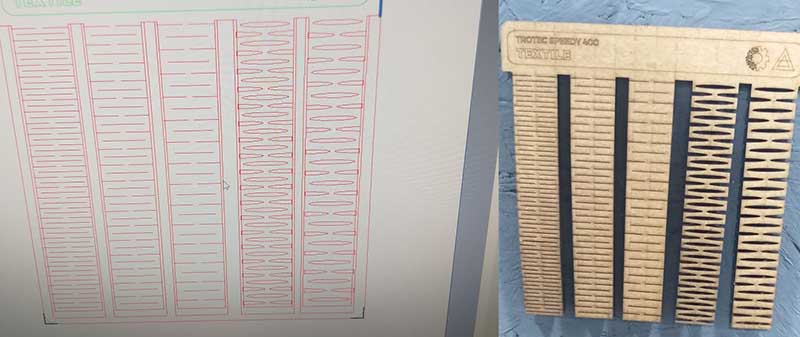
Extra Press-fitting test and living hinges:
We also did a press fitting to test it with Carboard, from Inkscape we selected the 2d models and make sure the color was set to RGB Red, then resize the page to exactly fit the Models, then follow the same procedure to print it/ export it to Jobcontrol software.
The same was done to the living hinges.
Individual assignments:
Vinyl Cutter:
This week we worked on CAMM-1 GS-24 Desktop Cutter CAMM-1 GS-24 Desktop Cutter, where we learn about the main parts:
- The cutter head, it is mount to a linear rail which is driven by a Digital control servo motor to control the X-axis and holds the knife/ pen.
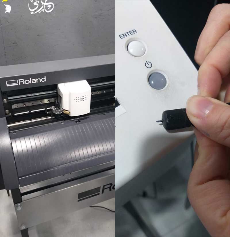
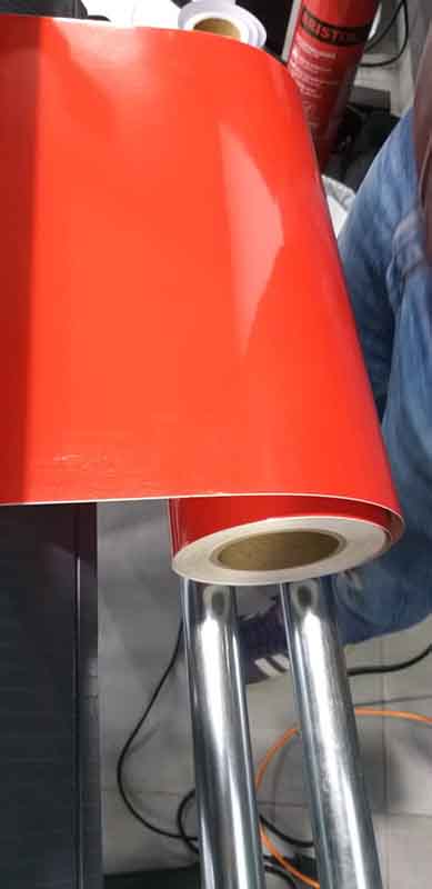
- The wheels are to control the Y-axis of the roll/ paper, and they are adjustable to change their locations, Then the roll is inserted in the back then clamp it by moving the lever (green).
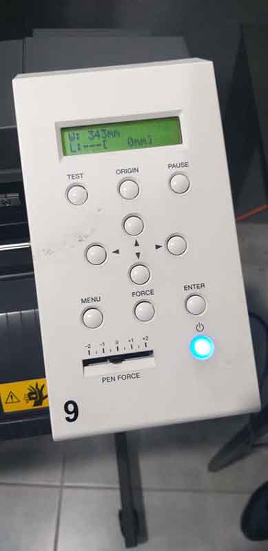
- Control panel, which you can store the machine defaults parameters on it, and connected to a computer, move the roll/ paper forward and backward, set the origin of the head, and adjust the pen force, and also do a test run to see the output to check if there are irregularities.
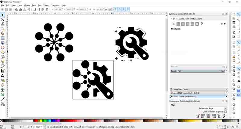
Vinyl logo cut:
I used this site to download two pictures in SVG format, then edited them on Inkscape.
Then I loaded the file into Cutstudio, then adjusted the height and width with the aspect ratio of the file, then I printed with the machine settings.
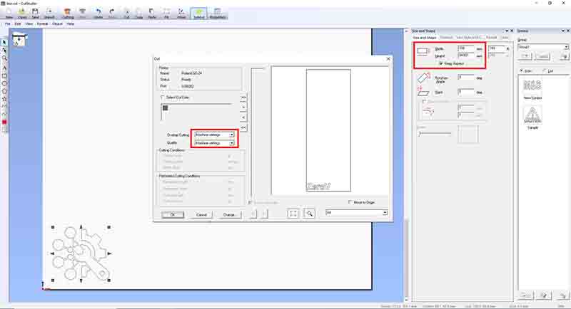
The output cut on red vinyl.
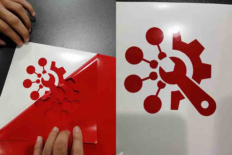
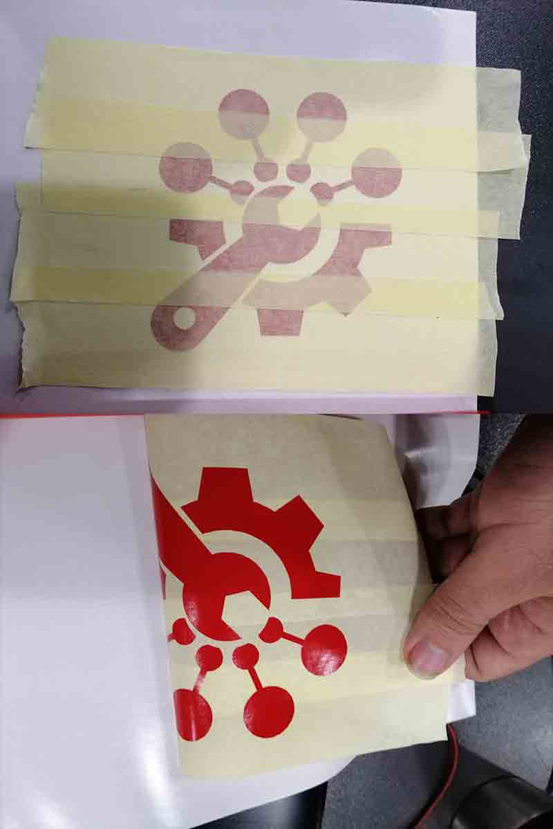
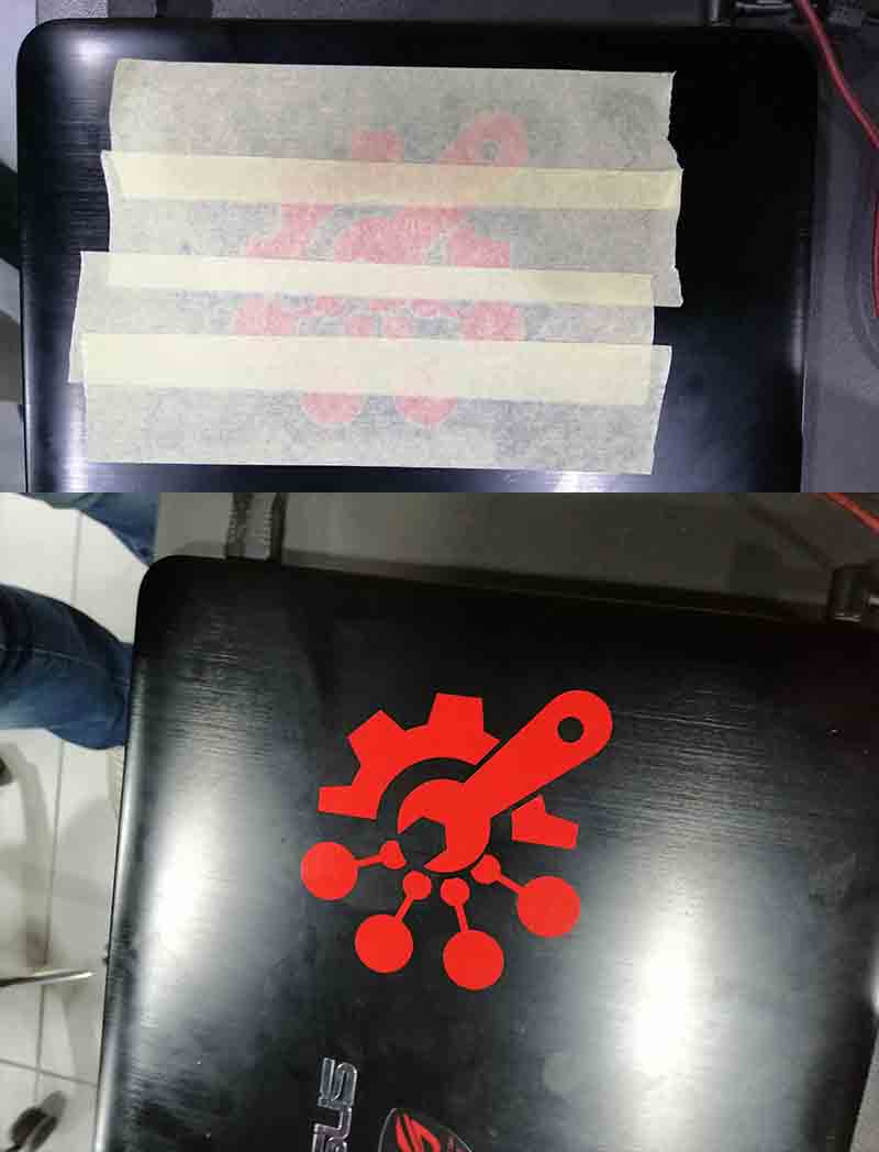
Then I out a paper tape to stick it on the back of my laptop, then peal it out, as shown the the next pictures.
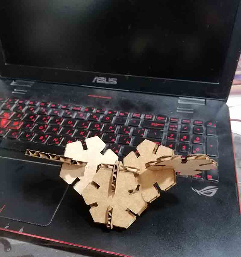
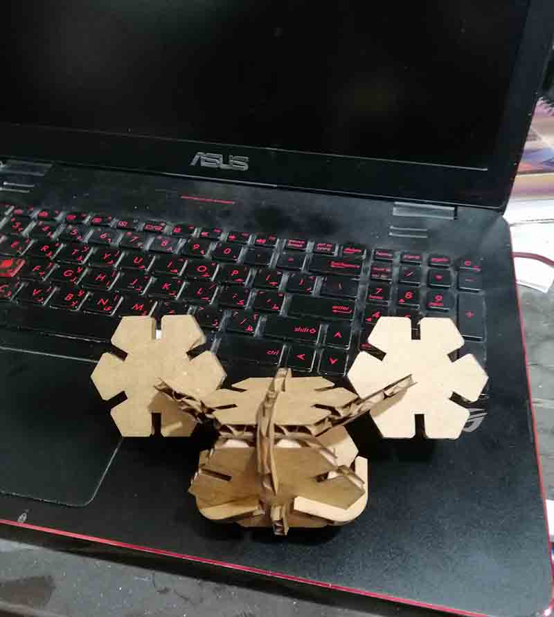
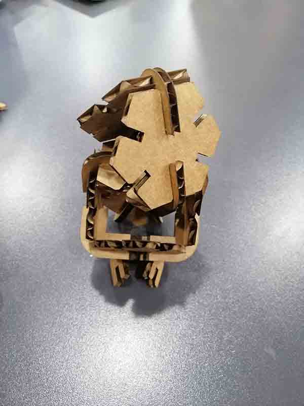
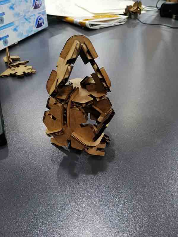
Hero shoot:
Parametric construction kit:
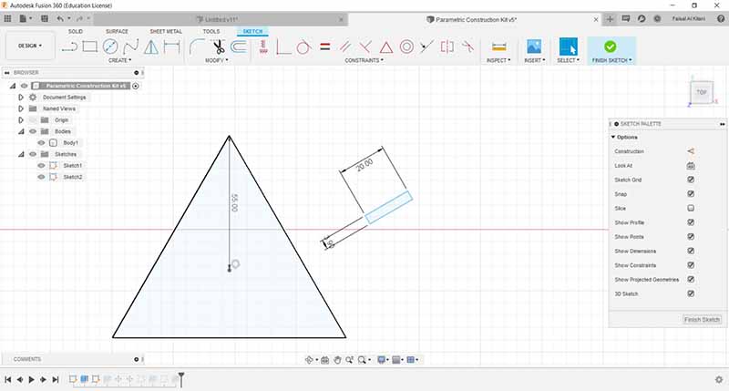
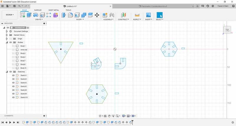
This week I used Fusion360 to make the kit.
First I made a polygon with three sides, and I made a rectangle with width of 3.9mm and 20mm length, and rotate it to match the one of the side of the triangle.
Then I constrain the rectangle midpoint of its width to the side of the triangle, then I made circular rotation to the rectangle with mid point of the surface of the triangle tp each side.
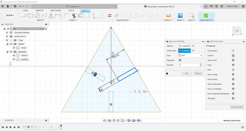
Note that when I change the height of the rectangle the other changed as well.
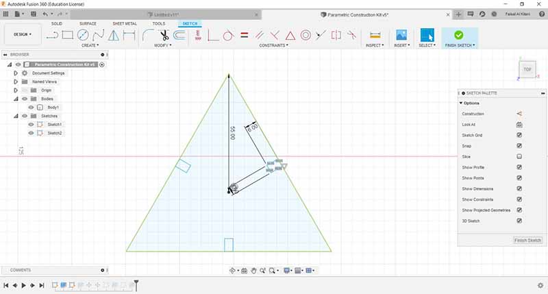
Then repeat the same operations to the other models.
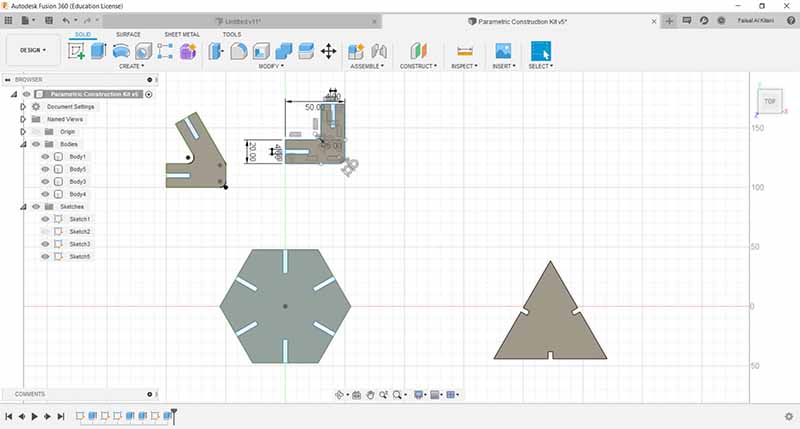
Then I made chamfer to all the edges of the gaps in the models, then I exported it as DXF (where I had many problems with export).
Update explanation:
Constrained method:
All of the rectangular are constrained to the same width and length, changing the value of one of them will change the others, by using the Equal constrain.
Width: 3.9mm, Length 8.0mm
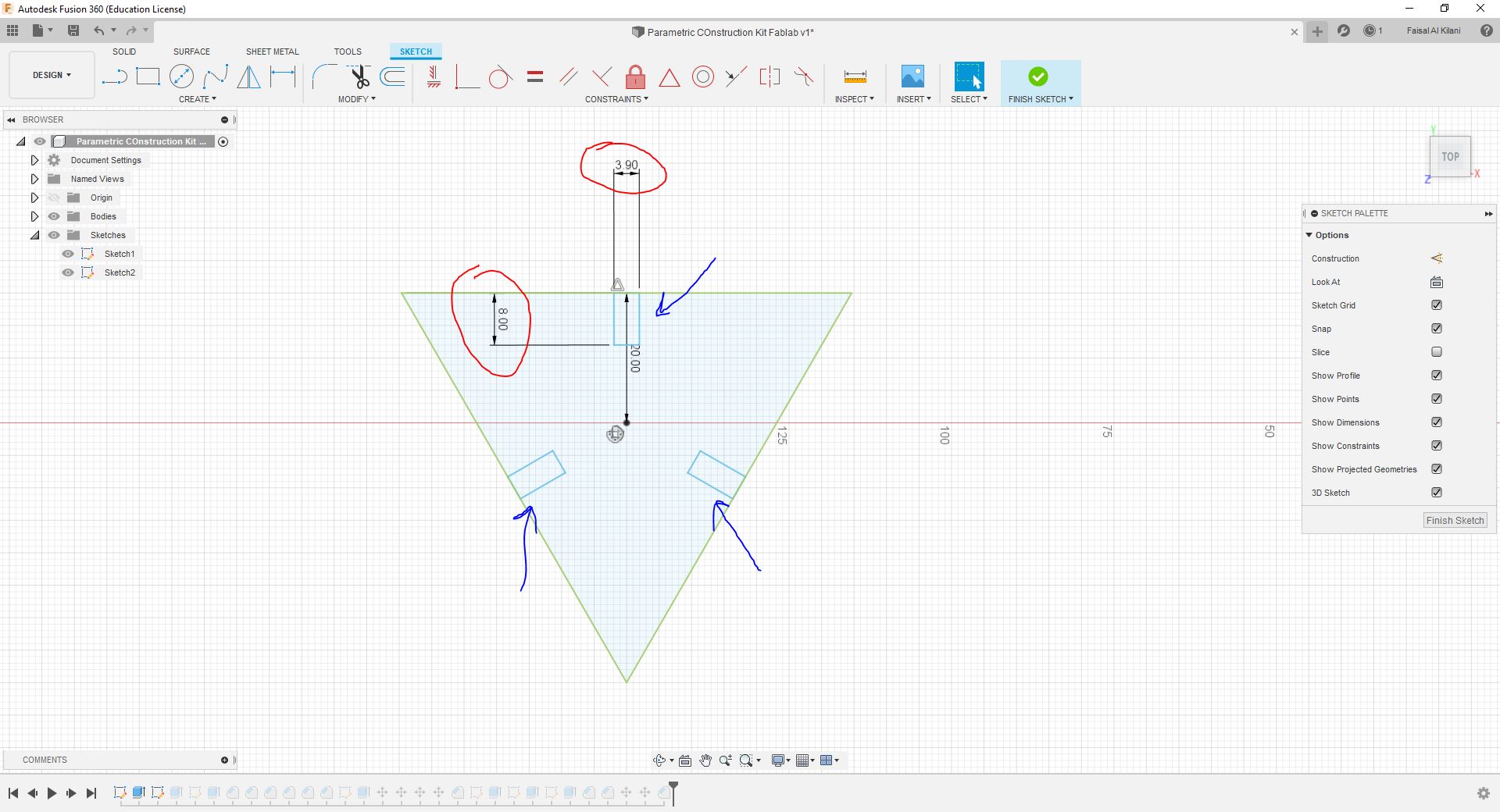
Here I change to the following values:
Width: 6.0mm, Length 12.5mm.
And you can see that, the shapes are changed accordingly.
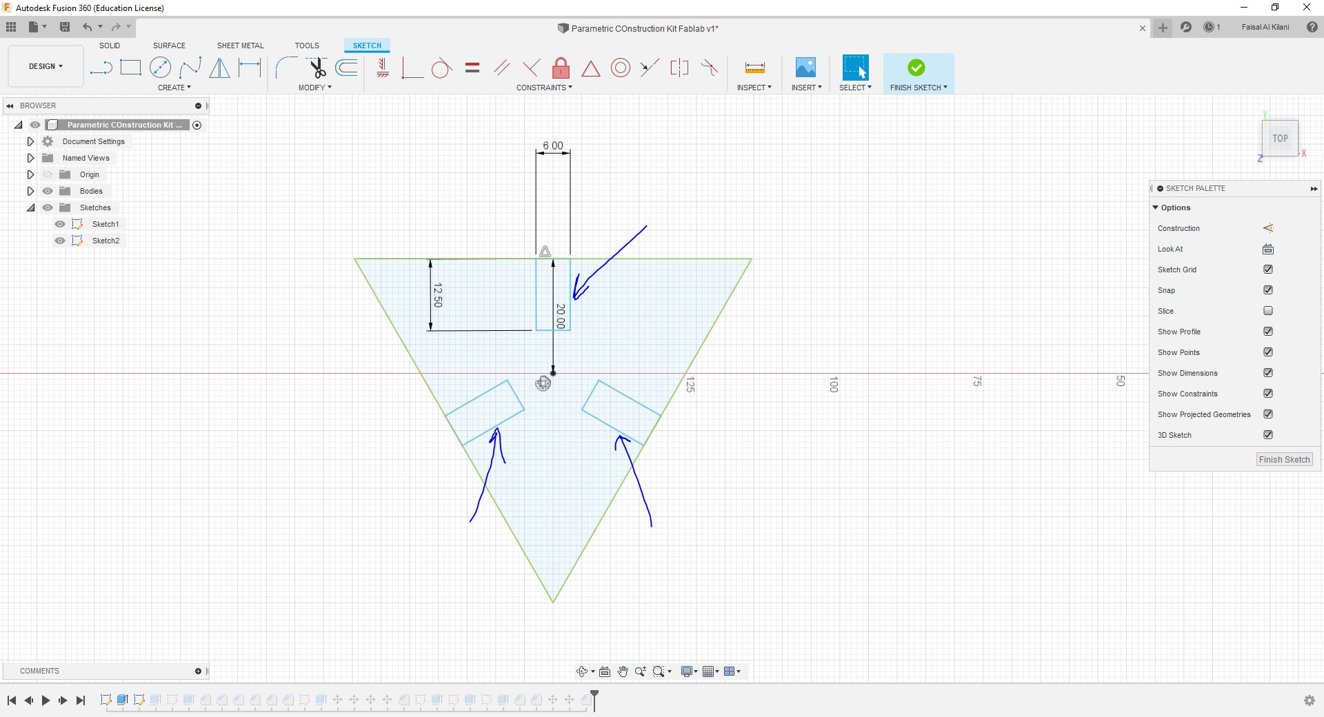
But this is not the right way to do this.
Changing parameters:
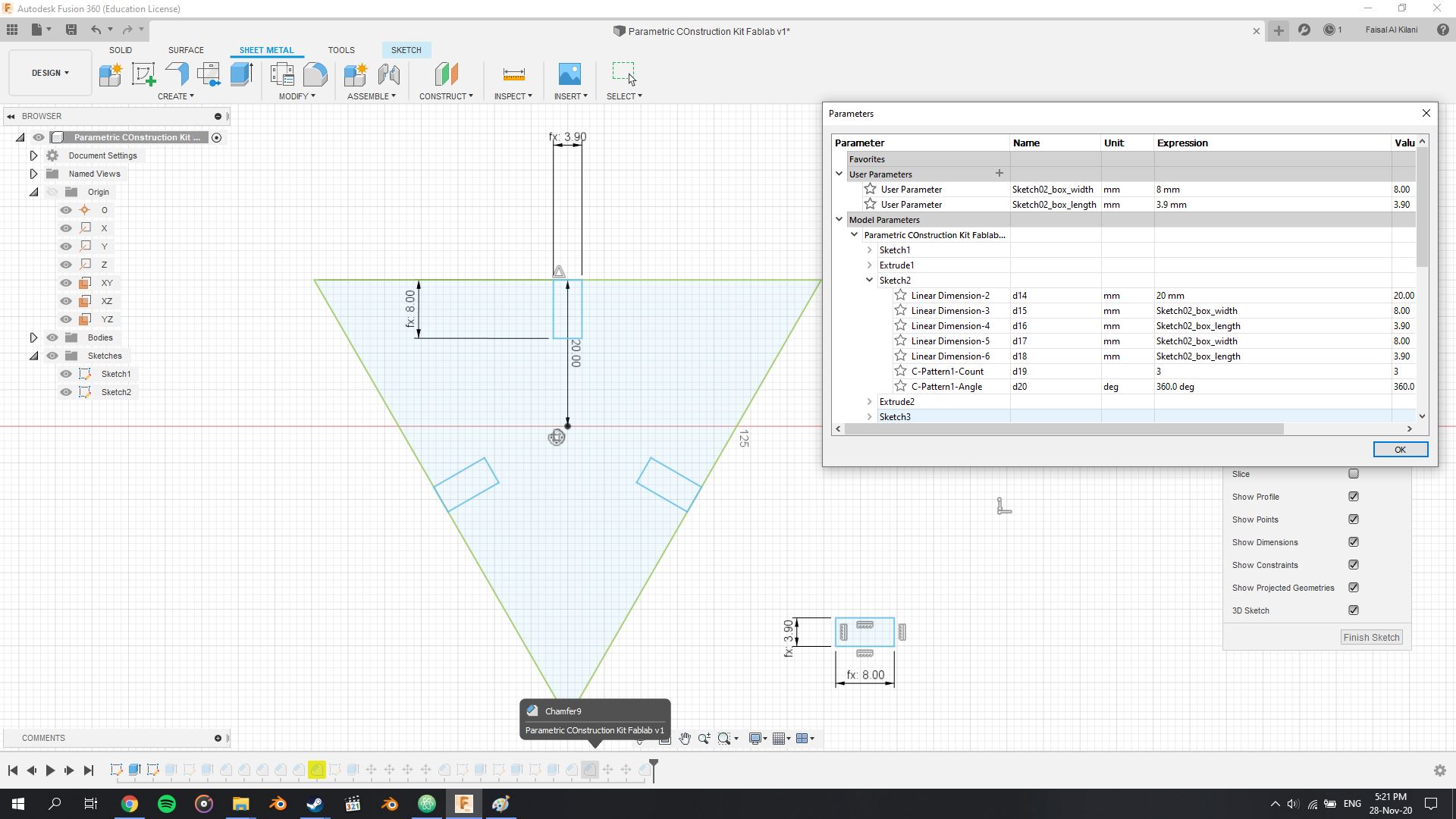
Using the Change parameters and it open a dialog window.
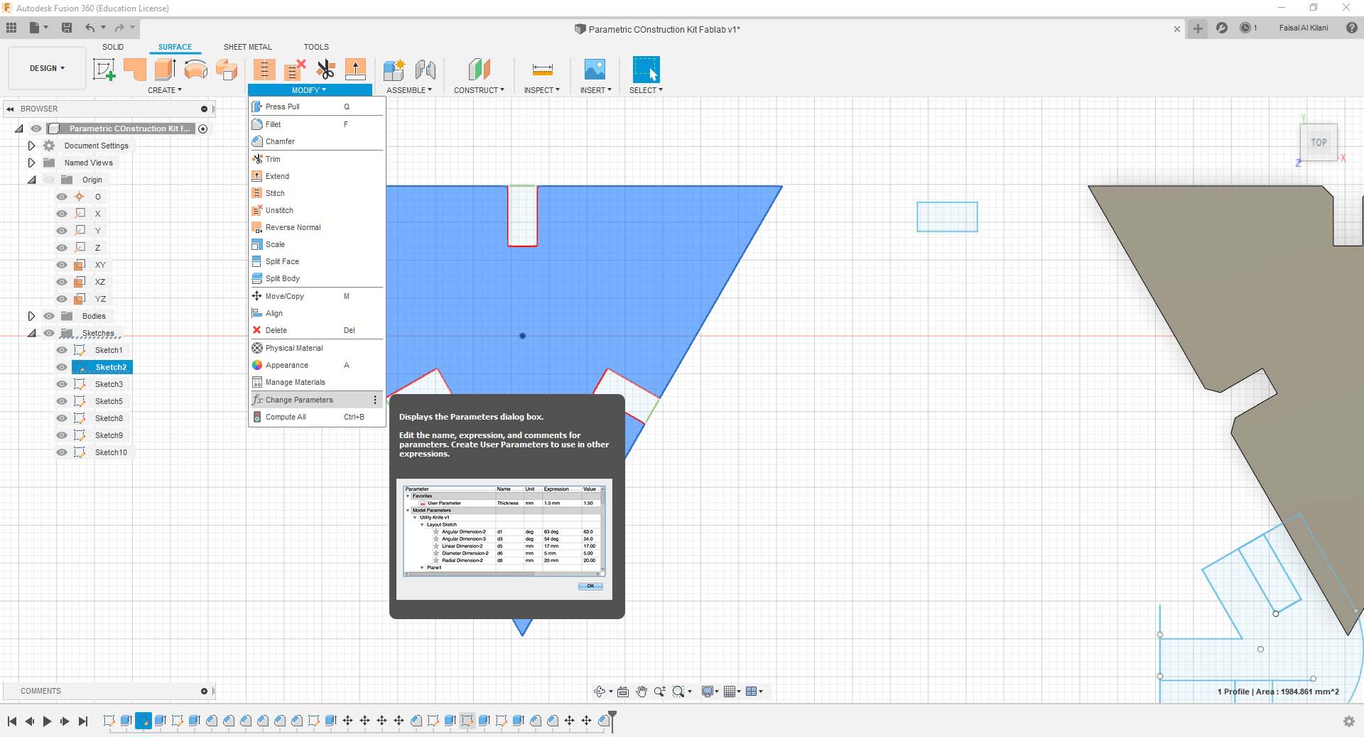
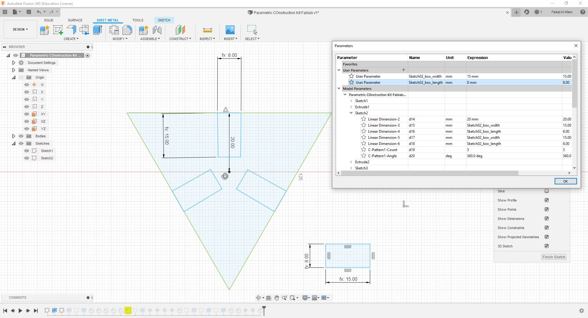
Adding a User Parameter, and a named them Sketch02_box_width and Sketch02_box_length, then put the value under the Expression column by the name of the user parameter as their values.
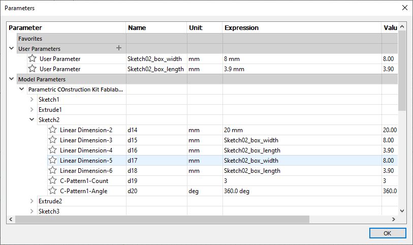
Width: 3.9mm, Length 8.0mm
Width: 8.0mm, Length 15.0mm
I had problems exporting using DXF:
The scale was always wrong, and the vectors were not connected; just lines not a complete shape.
Cutting parameters:
Cut:
Power: 60%, Speed: 01%, and frequency: 5000
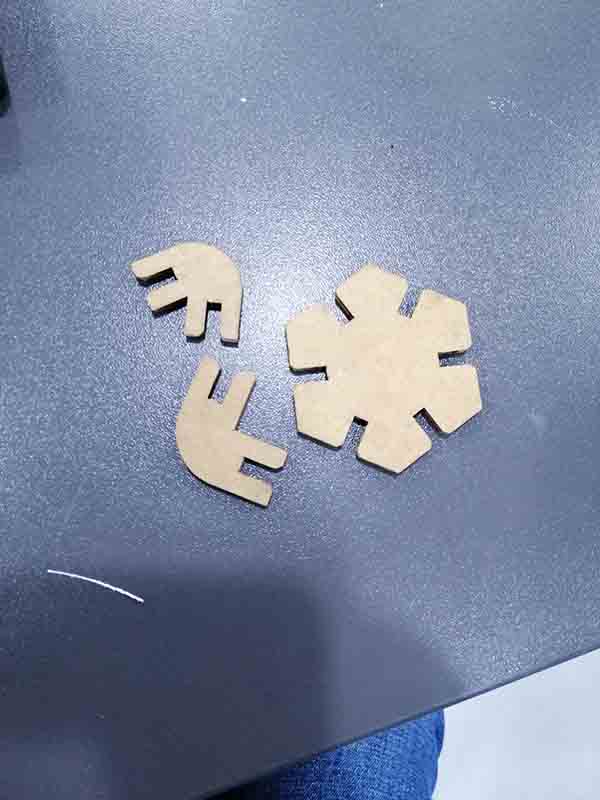
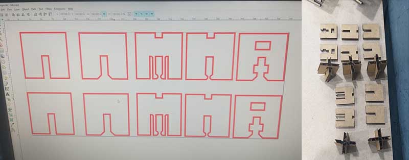
First test for the parametric construction kit:
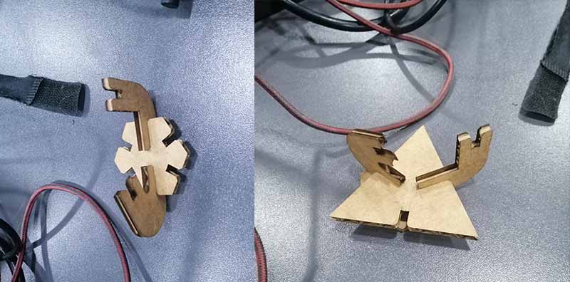
Results: The joints were bulky and needed to be smaller and have a deeper fittings, and the other shapes were not in the right size.
Redesign based the results:
I redesign and make it with two better joints with 60 degrees and 90 degrees angles and a hex polygon with chamfer fittings, and I did not use the triangle shape.
Cutting parameters:
Same as before:
Cut:
Power: 60%, Speed: 01%, and frequency: 5000
Hero shoot: