W19-Machine Week
What to do?
in this week, I will work with my team to build a vending machine with 2 products, each team member will work on specific part, check Norah,Sarah,Doaa pages to see their part of this week
my part is this week is to design the electronic circuit and design the pcb and test ti with aduino code and work with the team to give them the neecded parts to add for theier design of the physical parts of the vending machine
let's start with the first part, thing of the components that will be used int the machien, we came with a machine that has 2 products , the products will move out of the pay by a servo motor
the suer will need to insert a coin in the machine (if condition), then the machine will respond , and the user can press on one of 2 pushbuttons to pick between the right product and the left one
once he picked one, the the servo motor(360 dgree) of the picked product will rotate for a spacefic degrees untill the pruduct full out of the shelf, the the user can pick it up
some ledsss will be added to hsow the user the step of using the machine , so it can show wich step the user will ned to start with of which step to go to.....(this will be desicrbed in this page)
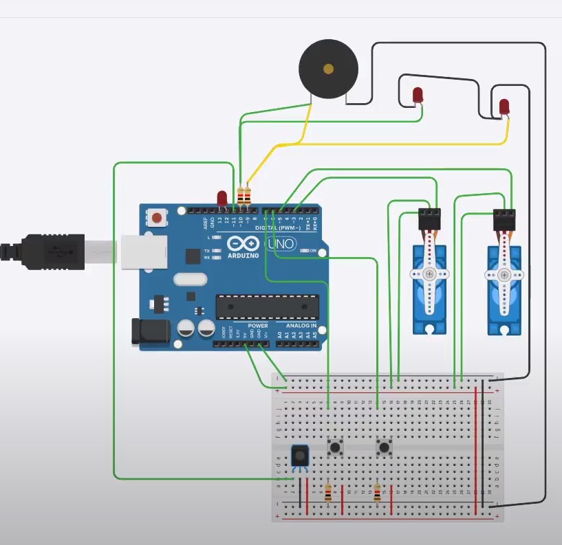
after knowing the needed parts for the machine, let's write the code for ot and test it in arduino :
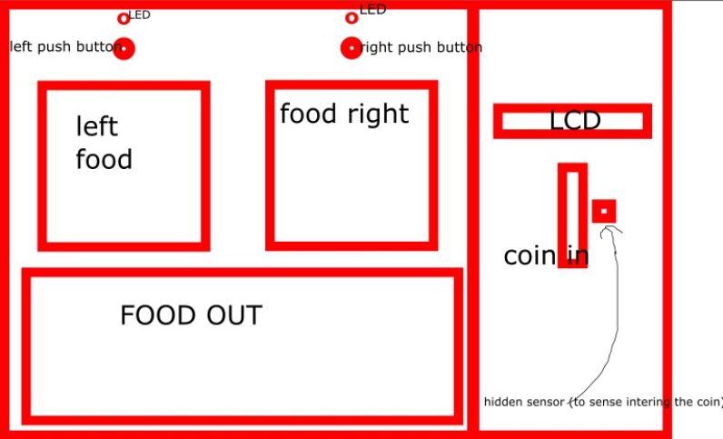
and this is the main look of the machine as first draft, "lcd may not be included":
and here is a simpel video to show how it works
and the arduino code is here:
#include Servo.h>

Servo myservoL;
Servo myservoR;

const int sens = 4;     // the number of the pushbutton pin
const int buttonPin = 2;     // the number of the pushbutton pin
const int sens2 = 8;     // the number of the pushbutton pin

const int ledPin =  13;      // the number of the LED pin
const int ledPinred =  12;

// variables will change:
int buttonState = 0;         // variable for reading the pushbutton status
int sensState = 0;         // variable for reading the pushbutton status
int sens2State = 0;         // variable for reading the pushbutton status

void setup() {
  // initialize the LED pin as an output:
  pinMode(ledPin, OUTPUT);
    pinMode(ledPinred, OUTPUT);

  // initialize the pushbutton pin as an input:
  pinMode(buttonPin, INPUT);
    pinMode(sens, INPUT);
pinMode(sens2, INPUT);


myservoL.attach(6);
  myservoL.writeMicroseconds(1500);  // set servo to mid-point
   myservoR.attach(5);
  myservoR.writeMicroseconds(1500);  // set servo to mid-point

}

void loop() {
  // read the state of the pushbutton value:
  sens2State = digitalRead(sens2);
  sensState = digitalRead(sens);
  buttonState = digitalRead(buttonPin);

  // check if the pushbutton is pressed. If it is, the buttonState is HIGH:

      if (sensState == LOW){
        goto buy;


        buy:
        if (buttonState== HIGH){

          digitalWrite(ledPin, HIGH);
          myservoL.writeMicroseconds(2000);
          delay(2000);
          digitalWrite(ledPin, LOW);

        }

     else if (sens2State== LOW){
        digitalWrite(ledPinred, HIGH);
        myservoR.writeMicroseconds(2000);
        delay(2000);
        digitalWrite(ledPinred, LOW);

      }}

   else {
    // turn LED off:
    digitalWrite(ledPin, LOW);
            myservoR.writeMicroseconds(1500);
        myservoL.writeMicroseconds(1500);
        delay(2000);

  }
}
nowl let's talk about pcb and eagle,fist I designde the pcb suing atmega328p becouse it ahs many pins for the lcd screen to support, HERE is the design:
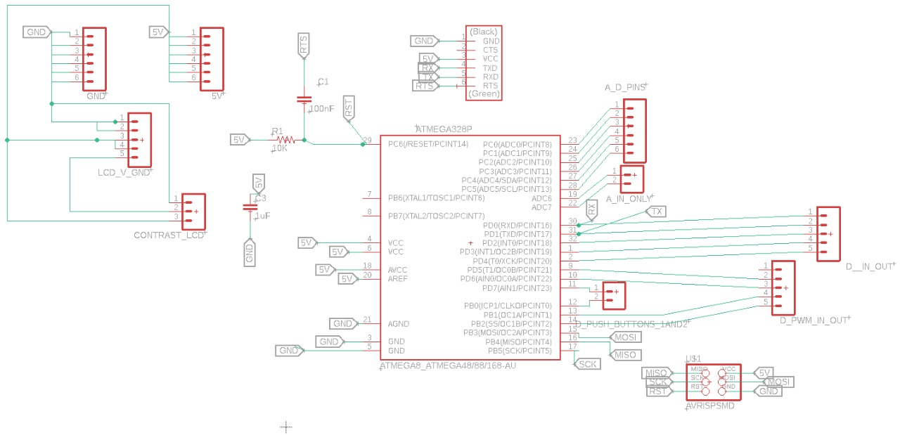

unfurtunatly and after many many trys, me and the members of the team could not work with atmega328p, it always burn....... we have tryes many times, and UNTIL NOW, nothing worked....
and for that, I will work using my beloved attiny44 and I will not use the lcd screen, buld leds to show the user the next step for him to use the machine
and with that, let's take alook at the design for attiny44:
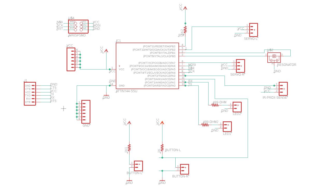
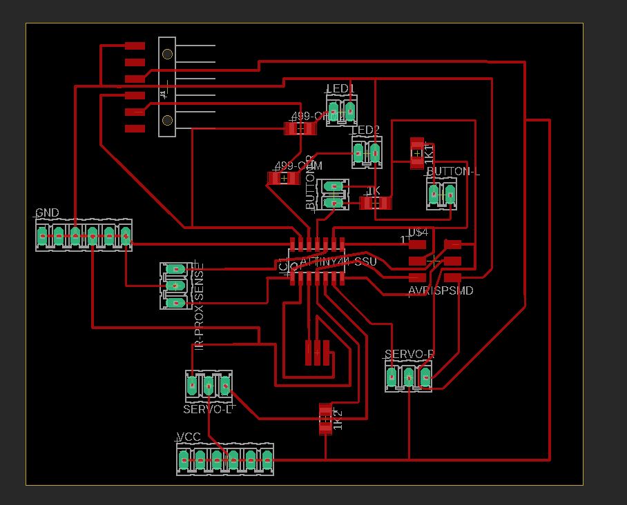
check eagele files for attiny44 HERE
and HERE
now, let's take a look at the caode that I have used for programming attiny84((changed from 44 , just to test....and for fun)), check it:
  int save;

int a;
int b;
void setup() {
pinMode(0, OUTPUT);
pinMode(1, OUTPUT);
 pinMode(2, INPUT);
    pinMode(3, INPUT);
    pinMode(4, INPUT);

    pinMode(7, OUTPUT);
    pinMode(8, OUTPUT);


}

// the loop function runs over and over again forever
void loop() {
int i=digitalRead(2);
int X=digitalRead(4);
int S=digitalRead(3);


if(S==0){
goto buy;


   buy:
if(i==0)
{
digitalWrite(0, HIGH);
   delay (50);
digitalWrite(1, LOW);
delay (50);

// for(a = 0;a <=5;a++){
// analogWrite(7,a);

// delay(1);

analogWrite(7,1);

delay(10);
analogWrite(7,0);
}


else if(X==0)
{
digitalWrite(1, HIGH);
delay(10);
digitalWrite(1, LOW);
 delay(10);
 digitalWrite(1, HIGH);
delay(10);
digitalWrite(1, LOW);
 delay(10);
  //myservoR.writeMicroseconds(2000);
    // delay(50);


analogWrite(8,1);

delay(10);
analogWrite(8,0);


delay(60);
}


else
{
digitalWrite(1, LOW);
digitalWrite(0, LOW);
}
}
}
check the video to understand how the circuit work after connecting it to 2 servo motor, 2 pushbutton and 2 led:
if the proximity sensor detect the coin, then you can pick from 2 products by pressenin on one of 2 pushbutton for each product
the video of the project will be upladed when the other team member send thier files to my after building adn inserting the electronics, very soon...
update---- the first video of the project is here, but I am still waiting for the other team member to send their work , for now.. the video include the work for (arduino code test, milling machine and attiny 84 code ant test the parts):