Exercise 15. 🌟 Molding and Casting 🍀 🌙
At the end of this exercise, I should be able to:
1. Evaluate moulding and casting materials by reviewing their safety data sheets .
2. Make and compare test casts for each of them.
3. Design approriate objects within the limitations of 3-axis machining.
4. Design a 3D mould around the stock and tooling that are available.
5. Mill (rough cut and three-axis cut) the 3D mould and use it to cast parts.
6. Demonstrate workflows used in mould design, mould construction and casting.
This exercise is very relevant to me as a chemical engineer. This is my comfort zone, but despite that safety should be my utmost priority because I will be dealing with chemicals that might be hazardous and have significan consequences to my health. Hence the first step is to read the Safety Data Sheet (SDS) of the chemicals involved in the making of mould process and the casting process.
In general when handling these molding and casting materials, we need to use covered shoes, long pants, chemical resistant gloves, safety googles and work in a well ventilated environment because the fumes from the chemicals might irritate lungs. The specific safety precautions MUST be read in the SDS.
To gain a better understanding on molding and casting process using the materials provided to us, namely:
1. EasyMold Silicone Rubber as Mold material.
2. SMOOTH-ON Sorta-Clear 37 as Mold material.
3. SMOOTH-CAST 300 & 305 as Cast material.
I watched these videos:
1. Making molds with EasyMold Silicone Liquid Rubber.
2. How to cast resin using Smooth-Cast 300.
3. How to make Food safe silicone mold using Sorta-Clear 37.
💎Review SDS of molding & casting materials and make test cast for each of them (Group assignment)
This part is a group assignment and the details can be seen HERE.
🌟Design a mold, mill it using three-axis cut finish and use it to cast part🌙
The workflow for this exercise are listed below:
1. Design using Fusion 360.
2. Creating toolpath for CNC milling machine.
3. Milling to make the mold of the mold.
4. Molding to make the mold.
5. Casting using the mold.
But due to FAB LAB is closed, I only able to do the Design work as describe below:
1. Design using Fusion 360
The first step of this exercise is to design the mold. I will use FUSION 360 to design the mold.
What does 3-axis milling mean? It means I need to design smooth tilted or curved surfaces instead of "steps" towards axis Z.
With this in mind, I decided to design a simple shappe that resemble a star and when put on a flat ground it looks like a climb to mountation top.
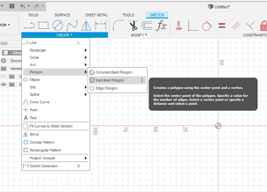
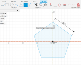
I started by drawing a regular pentagon with a random dimension using inscribed polygon and followed with a smaller dimension pentagon inside it.
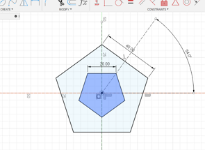
One thing to note is that the angle between nearest adjacent line for the 2 pentagon must be 36 degree, which translate to 54 degree in my drawing between the line and the horizontal line.
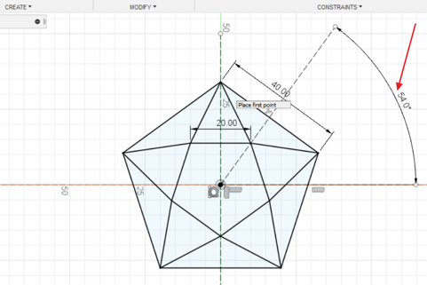
After that I need to connect all the corner line to resemble the star lines and then extrude the plane that will form a star shape.
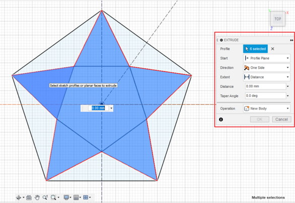
One thing to note is to change the taper angle so that I will have a tilted smooth z-direction, as shown below.
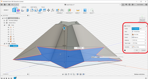
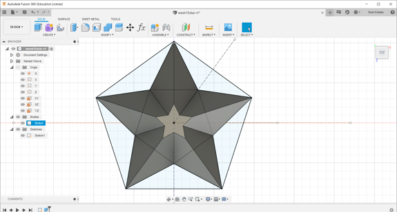
With that, now I have the star shape. The star is the final product, which the result of the casting process.
With this, the star shape that I have design is actually the mold of the mold that I will make.
Are you confused? Me too. But this video provides a clear explanation on this.
The mold of the mold is the mold where the molding resin will be poured to form the mold.
In SP Fab Lab, the mold of the mold is made of high density blue foam material and will be mill using CNC milling.
Since the mold of the mold need contain the molding resin, I need to include the box and bottom part of the design, as shown below.
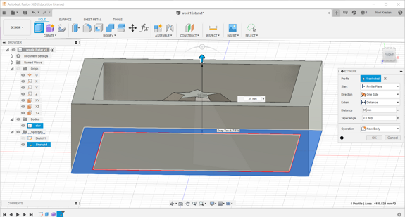
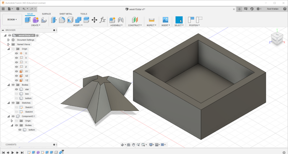
The box, bottom and the star must be a single body so that I can create a single toolpath to mill this design. Hence I combined all the bodies and below is the final result.One thing to note is that the box must higher than the star so that the mold will have a based.

to download the .stl file of the design
to download the fusion 360 design .f3d file of the design
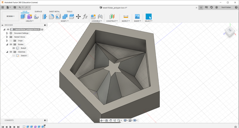
After finished creating the design, I received the feedback from my coach that I need to make the design smaller so that it will use less material to make the mold. Hence I change the design of the box into a polygon as shown below:
to download the .stl file of the design
to download the fusion 360 design .f3d file of the design
The model can be rotated and zoomed with the mouse/trackpad.
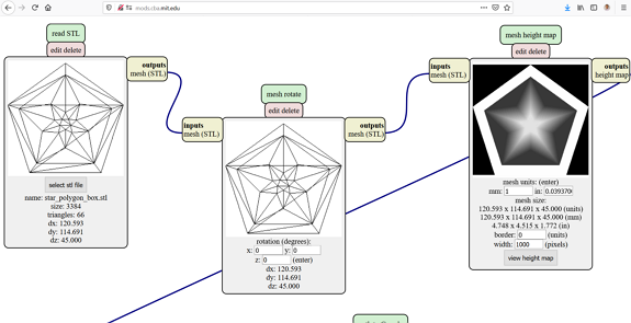
2a. Creating toolpath using mods
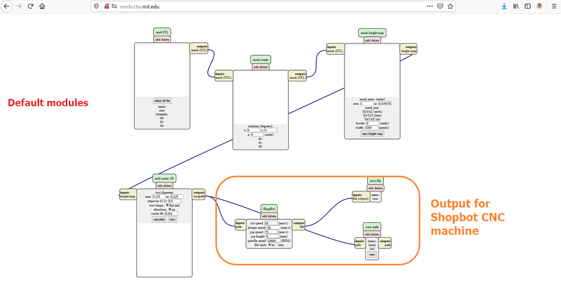
To create the toolpath for the work to be sent to the CNC milling machine, I will use mods.cba.mit.edu.
Under mods, select > program > open server program > Shopbot > mill 3D.
The input file for this mods is .stl file.
Below is the screen-captured of the settings in mods:
But since the output of this mod by default is for Shopbot CNC machine and the CNC machine that accessible to me is Roland, I need to modify the mods by connecting a "save module" after the "mill raster 3D module" and the toolpath produced is shown below:
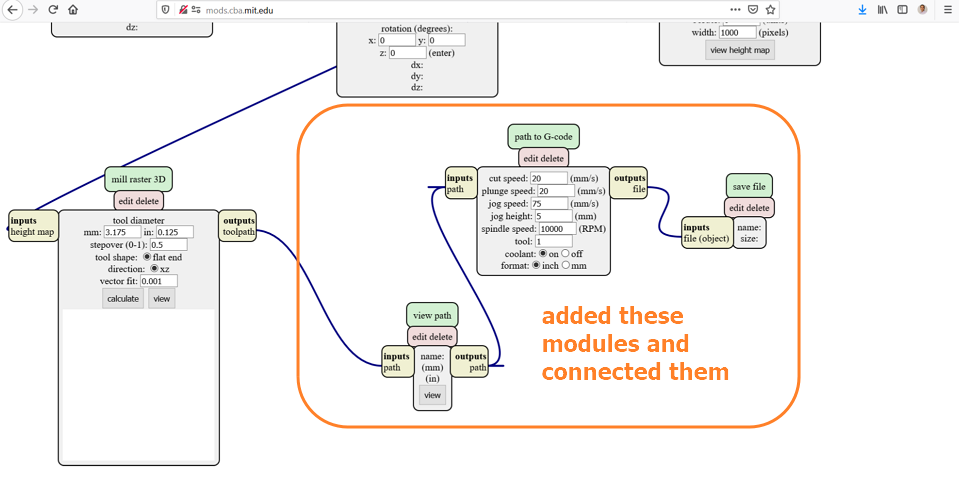
After connecting new modules, I added my stl file and set the modules as shown in the figures below:
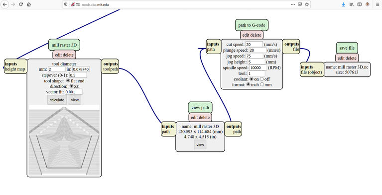
And the toolpath generated is shown in the figure below:
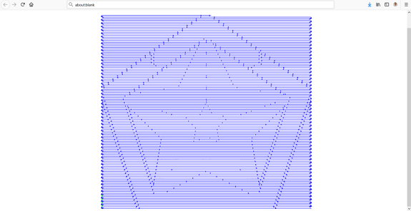
to download the toolpath in G-code
I also simulated the toolpath using CAMotics as shown in the video below:
2b. Creating toolpath using Fusion 360 CAM.
I encountered challenges in the milling process using the G-code I have created using mods previously. I will describe this challenge under the milling process.
With that challenge, one of SP Fab Lab coach, Mr Steven suggested to use Fusion 360 CAM to generate the g-code.
Fusion 360 CAM has many options in creating the toolpath (G-Code) which in this assignment it must be a 3D milling toolpath.
It is quite straighforward, from the design in Fusion 360, I selected "MANUFACTURE" option and under the "SETUP" tab I select new setup.
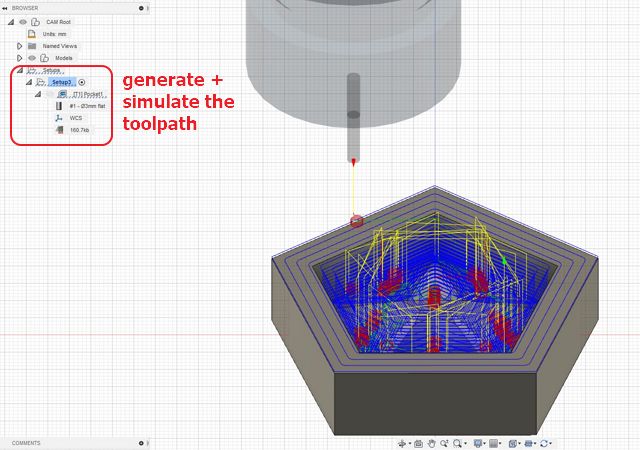
For this assignment, as advised by our coach, I use Pocket Clearing option and after measuring the dimension of the toolings that I will use, I set the tool/cutter as shown below:
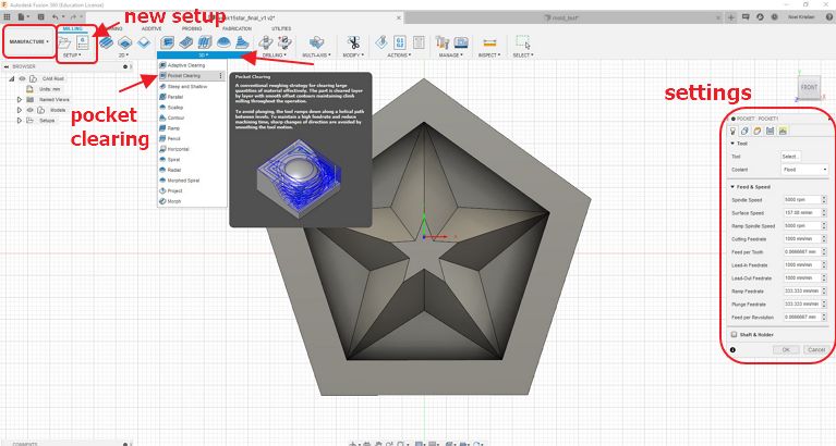
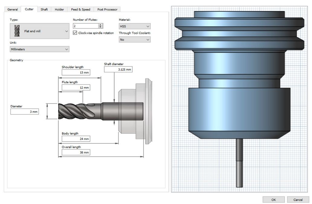
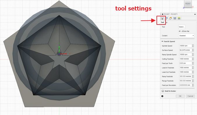
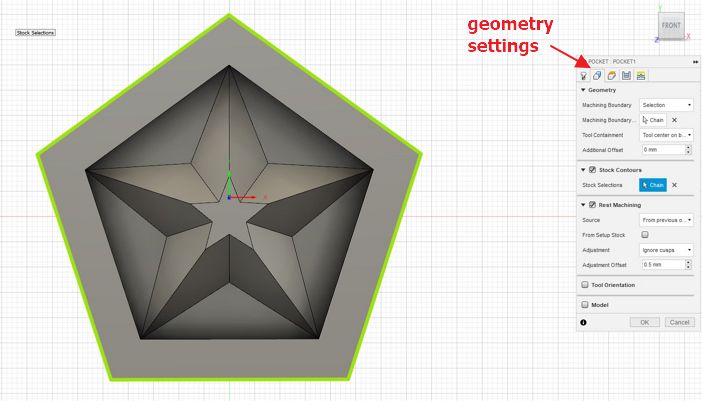

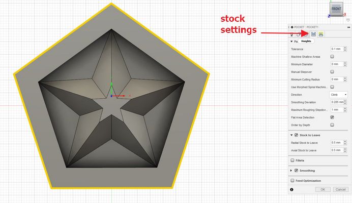
The full details of the settings that I use in this pocket clearing option can be seen below:
![]() With these settings, I generate the toolpath and simulate it as shown below:
With these settings, I generate the toolpath and simulate it as shown below:
to download the toolpath generated using Fusion 360 CAM
3. Milling to make the mold of the mold
In this section, I will describe the tools and CNC milling machine settings used.
The CNC milling machine that I will use for this assignment is Stepcraft D.420 that I have been using to make my circuit boards. The details of the CNC machine can be seen HERE.
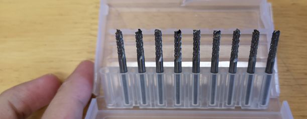
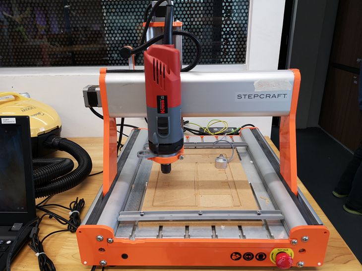 The major difference is the end mill that I will use in this assignment has a larger diameter (3 mm) and type is flat end.
 The zeroing of the Z-axis is done differently without the sensor. For this exercise, the z=0 is the top surface of the stock (in this case the high density blue foam).
The high density blue foam must be attached securely on the sacrificial board on the Stepcraft machine using double sided tape (best is to use industrial type double sided tape) so that it won't move during the milling process.
The rest of the steps are similar to the electronics production/design exercises.
🤔Problems encountered🤔😇
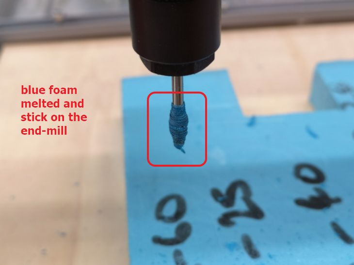
When I mill using my first toolpath generated using mods, the milling was unsuccesfull. This is because instead of milling, the end mill just melt the blue foam because of the heat generated during friction between the fast rotating end-mill and the foam. The blue foam sticking on the end-mill and the cut/melted part on the foam can be seen below:
Creating the toolpath and the milling process using the toolpath generated using CAM was easy and at the beginning, the milling process was successful.
But after around 2 minutes observing the milling process, I realized that the milling toolpath is different from what I have simulated in Fusion 360 CAM (simulation is shown in the video above).
The one executed by the CNC milling has many big circles outside the box of the design that I set in the stock settings.
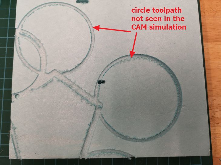
One of my peers, Ting Kok Eng also encounter similar problem.
(( Few days after I completed this exercise, my FabLab coach, Mr Steven analyzed my toolpath and fusion 360 design files and pointed that the post-processing setting that I have set, created the big circles toolpath outside the design.))
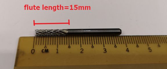
With these experiences, I realize that I can use mods to generate the toolpath but with certain constrain which is the flute length.
Hence, I changed the dimensions of the star to accomodate the flute length (15 mm).
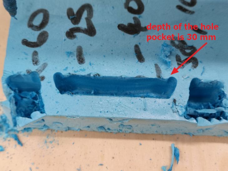
I made the depth of the design to be less than 15 mm and instead of using polygon box, I reverted back to simple square box.
to download the .stl file of the final design of the star
to download the .f3d file of the final design of the star
And with this design, I created the toolpath using mods following the same steps as above. The only difference is that this time I set the stepover to be 0.1 so that the z-direction milling is smoother.
Below is the simulation of the toolpath using Camotics.
to download the toolpath .nc file of the star generated using mods.
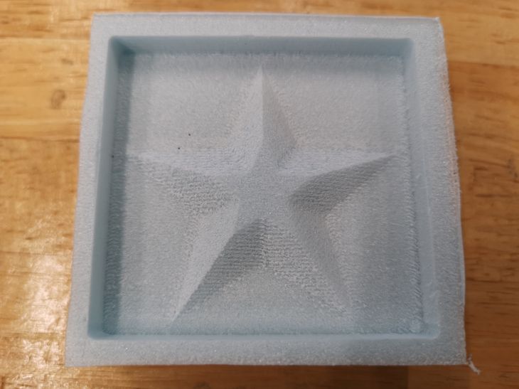
This time the milling process is smooth and successful as can be seen in the 2 videos below:
And this is the final result from the milling process:
4. Molding to make the mold
In this section, I will describe the molding process to make the mold
With the mold that I made above, I will use it to make a mold using the molding material mentioned in the group page which is the EasyMold Silicone Rubber.
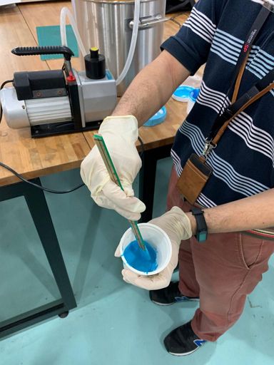
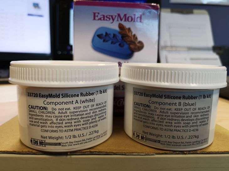 It is made of two components (blue and white) where they need to be mix in 1:1 ratio (mass).
Before starting, remember the safety precautions.
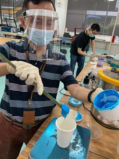
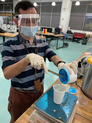
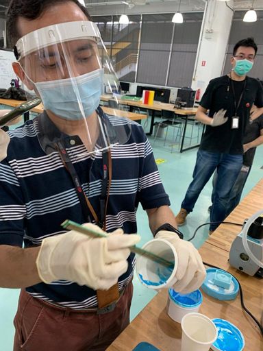
First we need to wear chemical resistant gloves, in this case I was wearing latex gloves.
Working area most be open environment with goot air circulation.
I was wearing a mask and a face shield because of the COVID-19 measures, it is not required for the safe handling of this EasyMold compound.
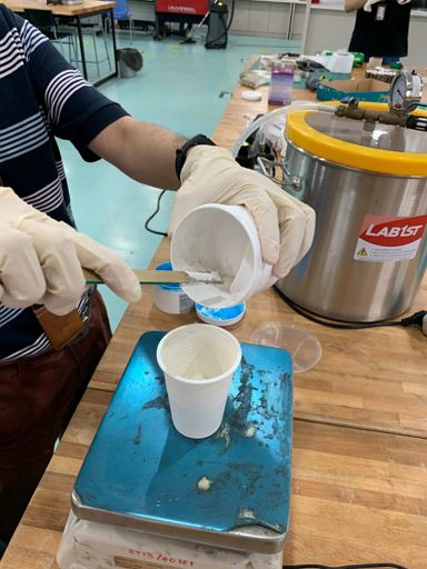
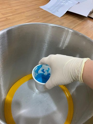
After estimating the quantity that I need by measuring the volume of the mold and multiplying it with 2 (assuming the density of the easymold is 2 gr/mL), on a plastic cup I weigh component B (blue color) first and then added equal weight of component A (white color).
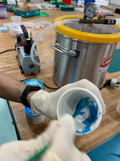
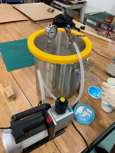
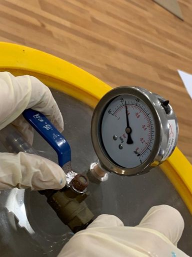
This step is meant to remove the air trap from inside the mixture.
According to the instructions written, this EasyMold does not require any vacuum equipment for degassing/deairing. But since the one that I was using is not a newly opened product (it was opened and used months before), I decided to do this step and it was a good call.
After taking the mixture out from the vacuum, it's time to pour it onto the mould.

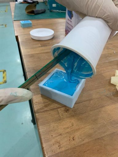
As written, the curing time for this EasyMold is 24 hours so I let it cure inside the FabLab for 2.5 days and after 2.5 days the result can be seen below.
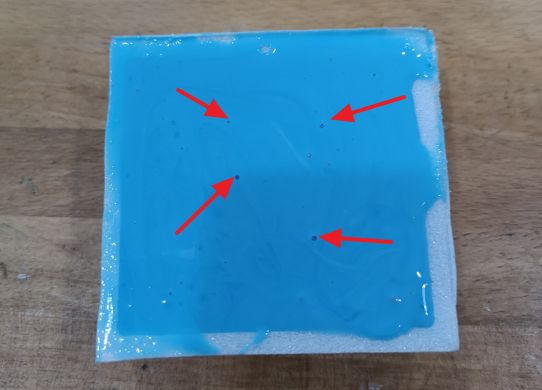 It can be seen there are few bubbles trap on that surface. This indicates that indeed there were air trapped inside the components and degassing it using vacuum was a good call even though not all the air trapped can be removed.
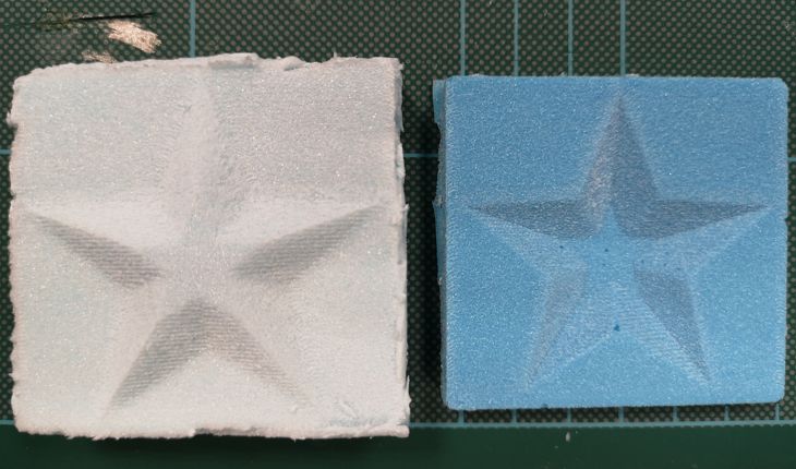
Now, i cut the side wall of the mold of the mold so that I can take out the mold easily and the final result of the mold is shown below next to it's blue foam mold.
5. Casting using the mold
In this section, I will describe the casting process to make the final products.
For the casting process, I will use Epicote 1003/1006 epoxy resin from a small local company.
My Fab Academy seniors in 2017 have used it previously and I follow their documentation closely as seen HERE.
As always safety is very important when handling any chemicals. In this case based on the safety data sheet, it is a must to wear chemical resistant gloves and work in the well-ventilated working environment.
The ratio between the epoxy resin and it's hardener is 3:1 (mass).
Upon mixing the 2, the mixture was stirred for 1 minute and then transfered to a vacuum chamber to degass the mixture. The degassing process takes around 2 minutes to complete.
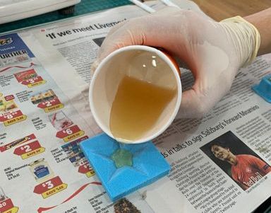
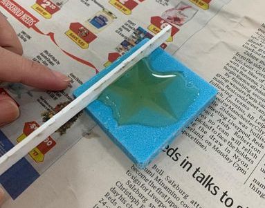
After degassing, the mixture is poured into the mold and I try to flatten the solution with the mold height using acrylic bar as shown in the pictures below.
I let it cure overnight (around 20 hours) in Fablab eventhough based on the technical specification sheet, it only takes 30 minutes to cure.
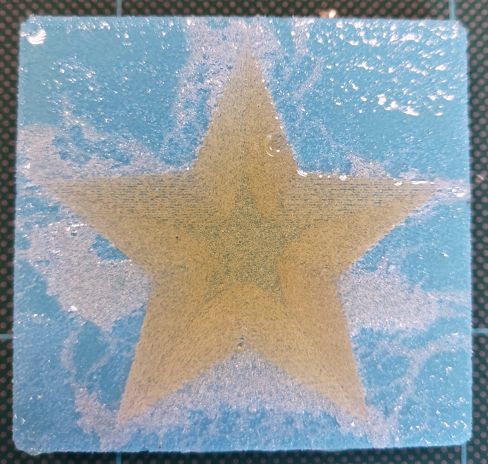
The result after 20 hours can be seen below.
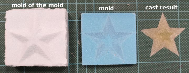
 Putting all the results side by side, the mold to make the mold made of high density blue foam, the mold made of EasyMold silicone rubber, and the casting result made of expoxy resin can be seen below:
Additionally as a chemical engineer, I also experimented using interesting materials for the casting process, namely paraffin wax and beeswax.
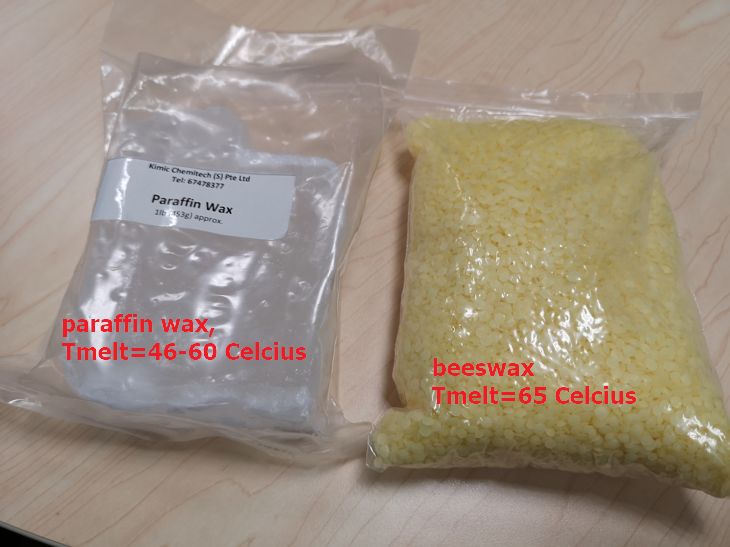 The melting point of these waxes are below 65 degree Celcius hence it is quite easy to melt and use it as casting material.
Once the paraffin is melted, the color remain the same, translucent white and for beeswax remain yellow once melted.
After heating each one of them so that it melts inside a small beaker, I poured the melted compound into the mold as shown in the below videos.
And below is the casted result after trimming the unflattened parts:
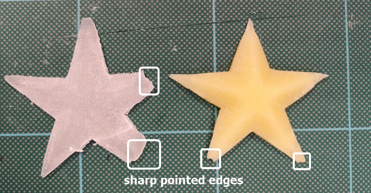 While main of the parts remain intact, the sharp pointed edges were very fragile and easily brake as seen above.
Looking forward to try different exotic materials to cast on this star mold =).