
The main purpose of this assignment is to add an input device on the board i have printed and solder an attiny44,let's first take
a look on what is an input device/inputing device.
Input device:
is a piece of equipment used to provide data to a computer system.
here in this assignment the computer system is a micro-controler always attached to the board.i have opted to use the
moisture sensor as an input device and the board which look like the one i have used in the communication assignment.
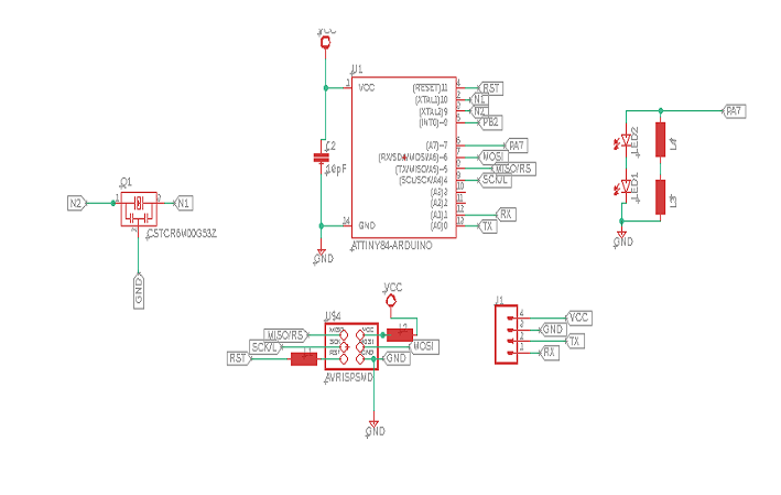
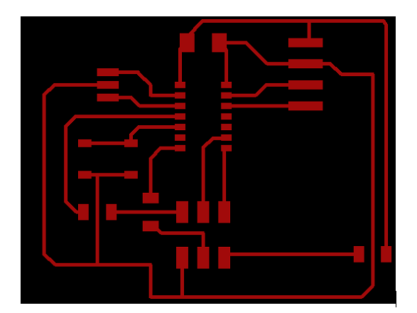
| Here is the eagle schematic Design: | The board design: | ||
 |  |
In the above schematic the simple modification is made becouse but it's abit little before we used to plug bluetooth hc-05 in Networking and
Communication but here we are going to replace hc-05 with the soil moisture sensor so,the rx on PA0 is replaced by auto on moisture
sensor.check on more information about Soil Moisture sensor for more details and how its connected to arduino.
| No | Electronic Components used |
|---|---|
| 1 | ATtiny44 |
| 2 | Capacitor |
| 3 | Pin headers |
| 4 | soil moisture sensor |
| 5 | led |
| 6 | Jumpers |
| 7 | Resistor |
| 8 | PCB |
Already the board is done what next and last is program the boards for it to ba able to communicate with this input device and turn off the led
lights when the input sensor senses water or that the land is wet as shown in the demonstration video at the end of this page the led lights turns
off.
I have used used arduino IDE download arduino and the usbtiny programmer to program my board as i did in other assignments.
After uploading the above code on my board the demonstration video below shows how my project is working.if the soil is dry/thirsty the led lights
are always on but when the soil is become wet may becouse of rain or when water is added like i did the led lights turns off immediately.
Files: