The main purpose of this assignment is to make two devices which can communicate to each other either with wires or wireless.
I have opted to use wireless communication as easiest way compared to method of using wires. I used to make other assignments I first designed the pcb in eagle where Bluetooth hc-05, Bluetooth hc-06, push button and led will be attached to the board I have made so as to communicate.
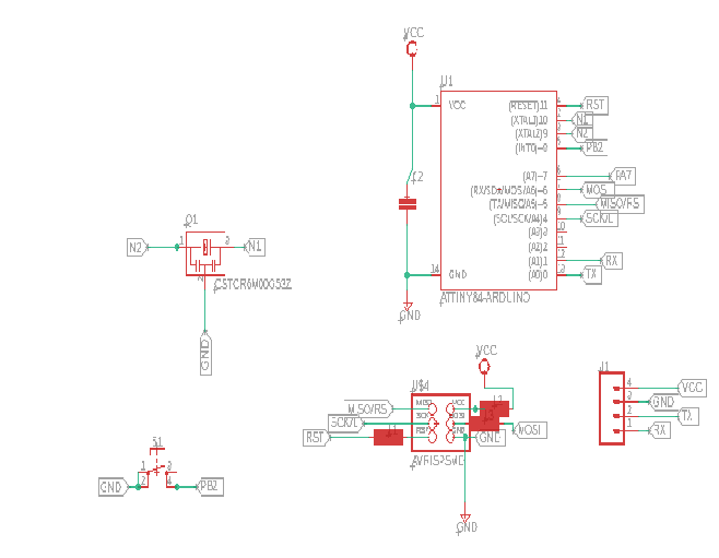
Here is the eagle schematic look of hc-05:
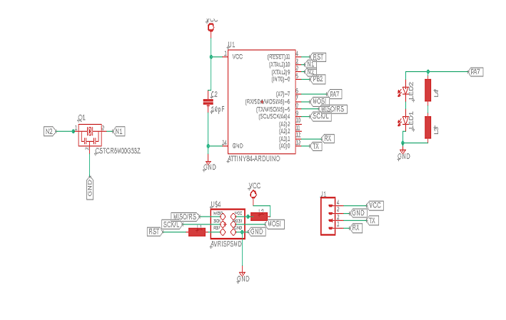
the eagle schematic look of hc-06:
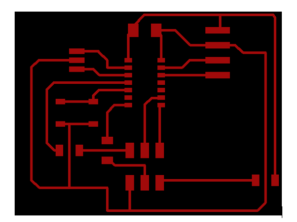
The next step was to prepare the eagle board as shown in the image below:
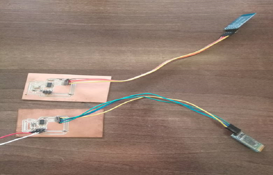
And this is the final outlook of the board after soldering all component needed to complete the job.
These are component names i have used in this assignment:
No
Electronic Components used
1
ATtiny44
2
Capacitor
3
Pin headers
4
bluetooth hc-06
5
bluetooth hc-05
6
led
7
push button
8
Jumpers
9
Resistor
10
PCB
Already the board is done what next and last is program the boards for them to communicate in wireless mode.
I used arduino ide as the most simple programming software for beginners.
As we have used hc-05 and hc-06 of them needs to be in master mode and the other will be used in slave mode.
According to the nature of the above BT module hc-05 can be used as master or
slave but hc-06 can only be used in slave mode easly.
PROGRAM ON MASTER SIDE
#include SoftwareSerial.h
SoftwareSerial BTSerial(PA0, PA1);
int state = 0;
const int ledPin = 8;
const int buttonPin = PB2;
int buttonState = 1;
void setup()
{
BTSerial.begin(38400);
pinMode(ledPin, OUTPUT);
digitalWrite(ledPin, LOW);
pinMode(buttonPin, INPUT);
digitalWrite(buttonPin, HIGH);
}
void loop()
{
if(BTSerial.available() > 0)
{
// Checks whether data is comming from the serial port
state = BTSerial.read(); // Reads the data from the serial port
}
// Controlling the LED
buttonState = digitalRead(buttonPin);
if (buttonState == LOW)
{
BTSerial.write('1');
}
else
{
BTSerial.write('0');
}
if (state == '1')
{
digitalWrite(ledPin, HIGH); // LED ON
state = 0;
}
else if (state == '0')
{
digitalWrite(ledPin, LOW); // LED ON
state = 0;
}
}
CODES ON MASTER SIDE
#include
SoftwareSerial BTSerial(PA0, PA1);
int state = 0;
const int led = PA7;
const int button = 2;
int buttonstate = 1;
void setup()
{
//Serial.begin(9600);
BTSerial.begin(38400);
pinMode(led, OUTPUT);
digitalWrite(led, LOW);
pinMode(button, INPUT);
digitalWrite(button, HIGH);
}
void loop()
{
if(BTSerial.available() > 0)
{
// Checks whether data is comming from the serial port
state = BTSerial.read(); // Reads the data from the serial port
// Serial.println( state);
}
// Reading the button
buttonstate = digitalRead(button);
if (buttonstate == LOW)
{
BTSerial.write('1'); // Sends '1' to the master to turn on LED
}
else
{
BTSerial.write('0');
}
if (state > 0 )
{
digitalWrite(led, HIGH); // LED ON
state = 0;
}
else if (state < '0')
{
digitalWrite(led, LOW); // LED ON
state = 0;
}
else
{
//print nothing
}
}
After uploading the above code on the two separate boards we have made .
The video below shows how the project works:
The original files used for this assignment can be downloaded Download