

Objectives
The purpose of this week session was to complete a individual task and group task. This session is introduction to Printed Circuit Boards (PCB) and Electronic Circuits. The following is the breakdown of tasks for Week 4.
Individual Task: Build a PCB and Program it.
Group Task: Test the Tolerance of Roland 50 Mill Machine for PCB at FabLab.
Individual Task: Build a PCB and Program it!
This task was about using the Roland 50 Mill machine in the FabLab for printing a PCB Board. The layout for the PCB was provided by the Fab instructor as image file. The following are the steps taken to complete this task.
The task began by importing the image file of the PCB layout in the Fab Module website (http://fabmodules.org/).
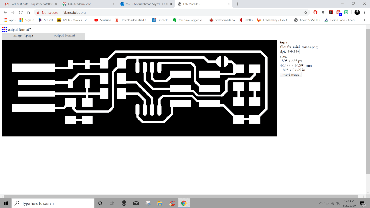
Then the output format for the fab module was defined and Roland Mill was selected from the drop down menu.
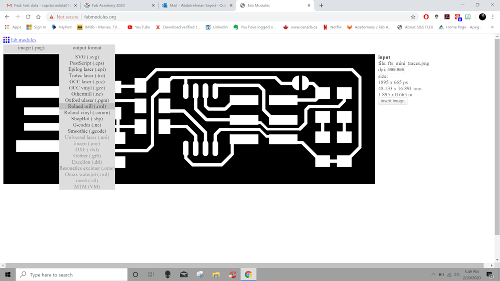
Then define the process for PCB traces (1/64) from the drop down menu.

Set the parameters for the trace by changing the values on the output panel on the right as shown below.

Then click on the calculate button in order to generate the trace for the layout.

Finally, Save the file as .rml format and copy it to the flash memory in order to be imported in to the Roland Mill software.
In order to create the outline for the PCB, click on the image tab and upload the outline image provided by the Fab Instructor to the Fab Module website.

Then the output format for the fab module was defined and Roland Mill was selected from the drop down menu.
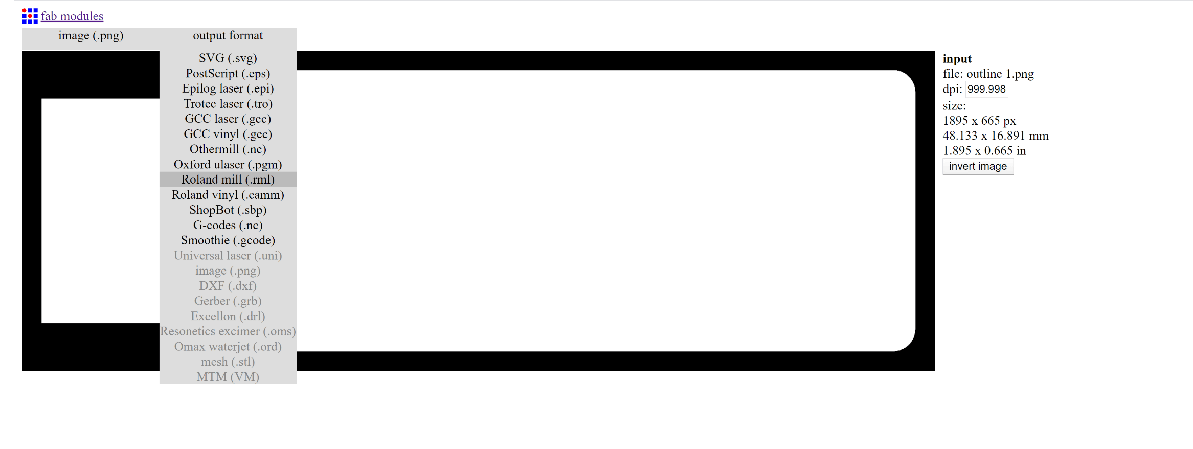
Then define the process for PCB outline (1/32) from the drop down menu.
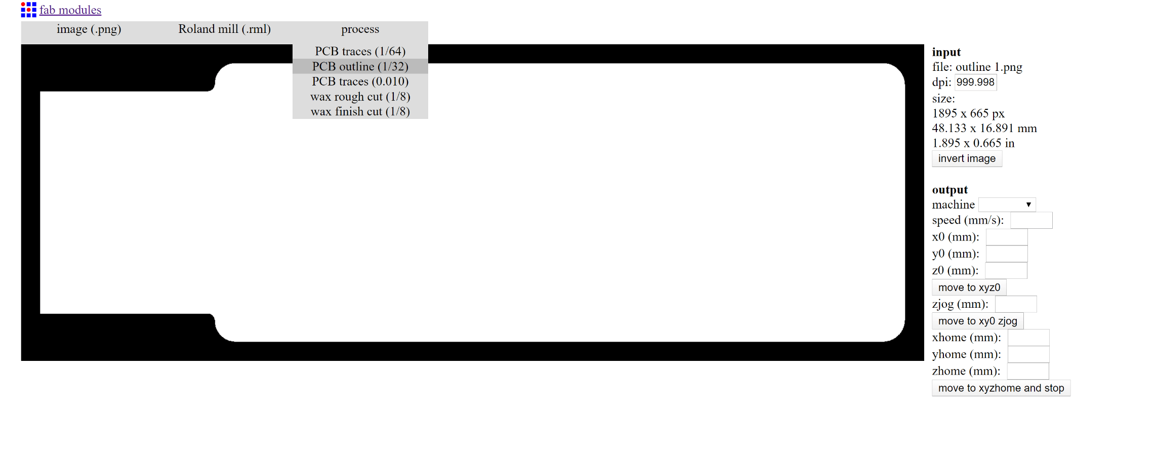
Set the parameters for the outline by changing the values on the output panel on the right as shown below.
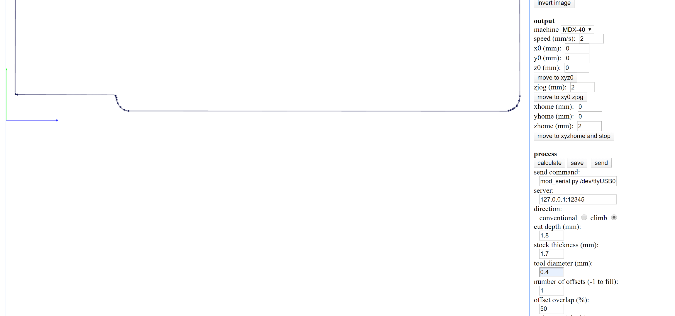
Then click on the calculate button in order to generate the outline for the layout.
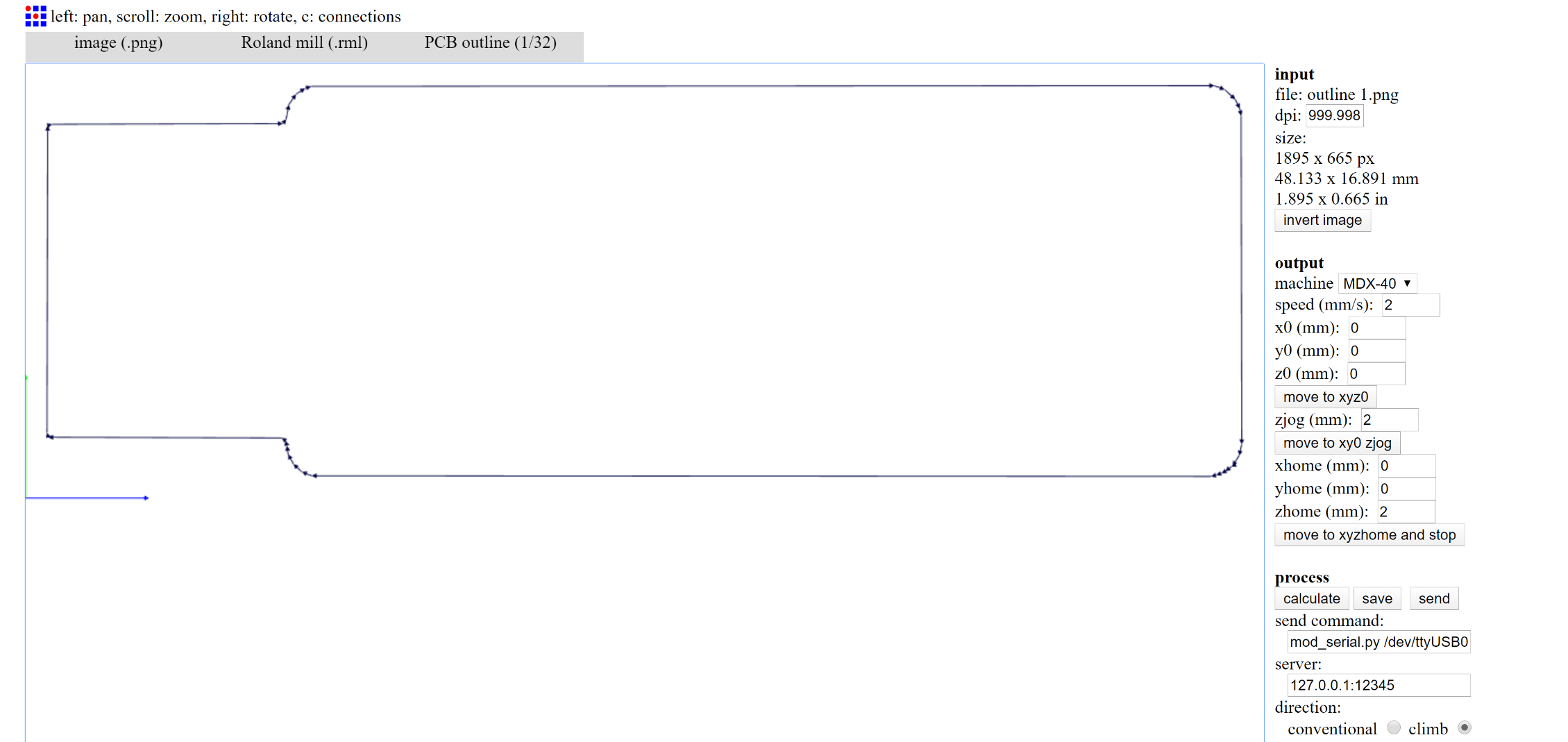
Finally, Save the file as .rml format and copy it to the flash memory in order to be imported in to the Roland Mill software.
In order to Setup the Roland Mill Machine for cutting the PCB, follow the steps mentioned below.
Begin by cleaning the work space in the Roland Mill Machine.
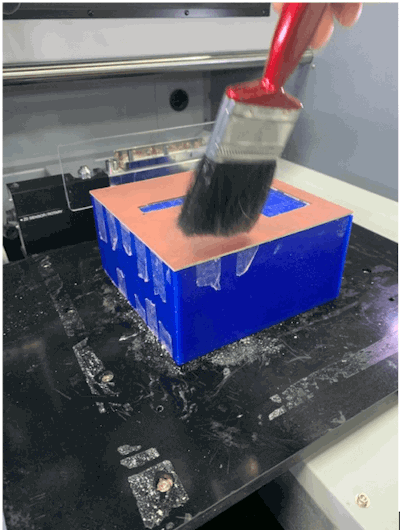
Then mark a point on the copper plate to set it as reference for the calibration of axis of the machine.
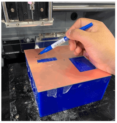
Then calibrate "X" and "Y" axis of the machine by manually moving the jog wheel and bringing the pointer closer to the marked reference point. When over the marked point then click and hold the origin button to set as origin point for the "X and Y" axis.

In order to calibrate the "Z" axis, we would need to place the Z axis probe near the defined point and then manually move the pointer over the probe. Once the axis are calibrated then the tool can be moved to home position and probe can be removed from the work space.
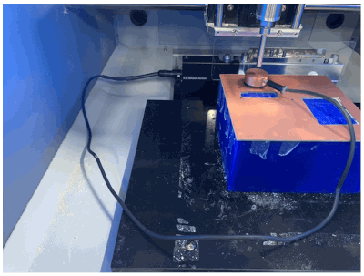
Then on the software side, open the program for the Roland Mill and Click the Cut option from the selection wheel. Then click on the "Add" button to add the .rml files for trace.
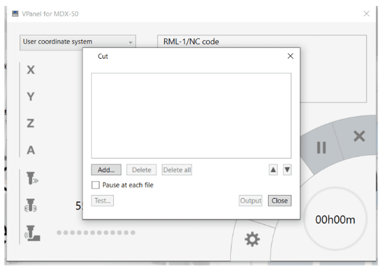
Once the files are added then "Output" button can be pressed and cutting process on the PCB can begin.

For the outline on the PCB, add the files for outline and click on "Output" button to initiate the process of outlining on the board.
The next stage in this task is to Solder the components of USB onto the printed PCB and following is the list of components that were used for this task.
Resistors - 11 ohm (Qty 2).
Resistors - 499 ohm (Qty 2).
Resistors - 49 ohm (Qty 2).
Zenor Diode - 3,3 volt (Qty 2).
Red LED - Qty 1.
Green LED - Qty 1.
Capacitor- 100 nF (Qty 1).
3 Pin Holder - Qty 2.
Atiny 45 or 85 - Qty 1.


In order to Setup the Roland Mill Machine for cutting the PCB, follow the steps mentioned below.
The next stage in this task is to Solder the components of USB onto the printed PCB and following is the list of components that were used for this task.
Group Task: Test the Tolerance of Roland 50 Mill Machine for PCB
This task was about using the Roland 50 Mill machine in the FabLab for printing a PCB Board to test out the tolerance of the machine. The layout for the PCB was provided by the Fab instructor as image file. The following are the steps taken to complete this task.
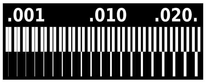
The task began by importing the image file of the PCB layout in the Fab Module website (http://fabmodules.org/).
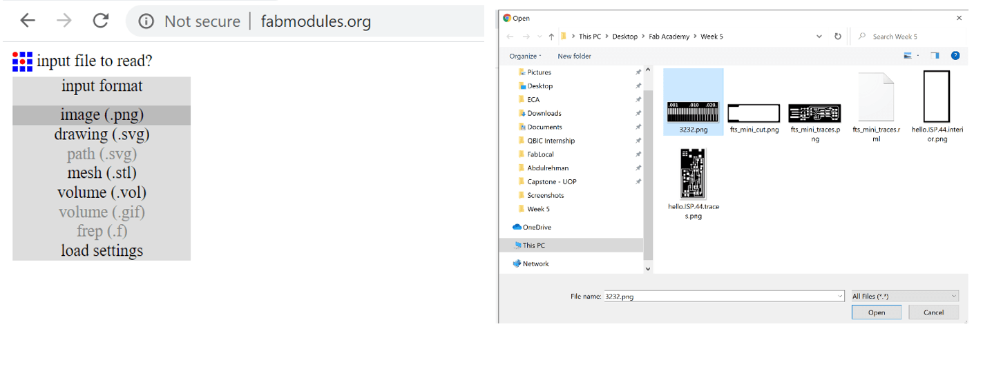
Then the output format for the fab module was defined and Roland Mill was selected from the drop down menu.
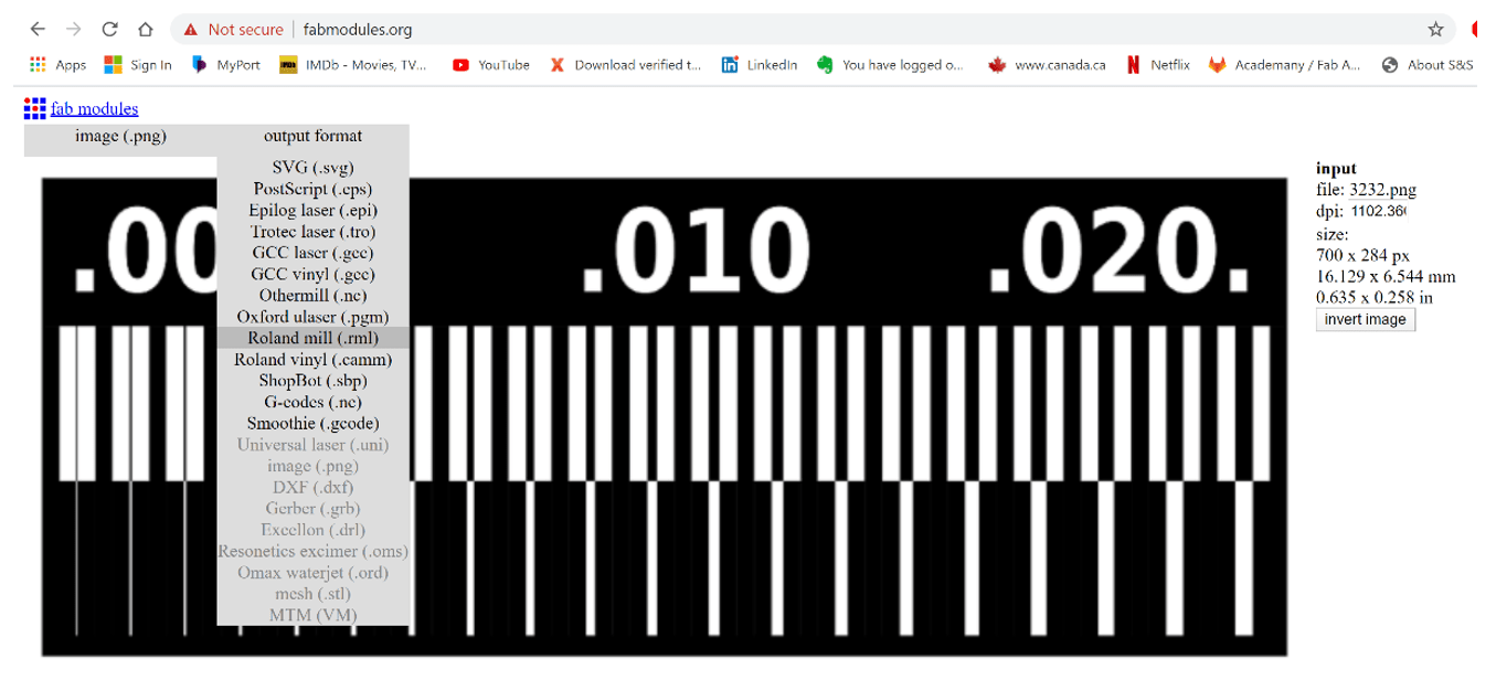
Then define the process for PCB traces (1/64) from the drop down menu.
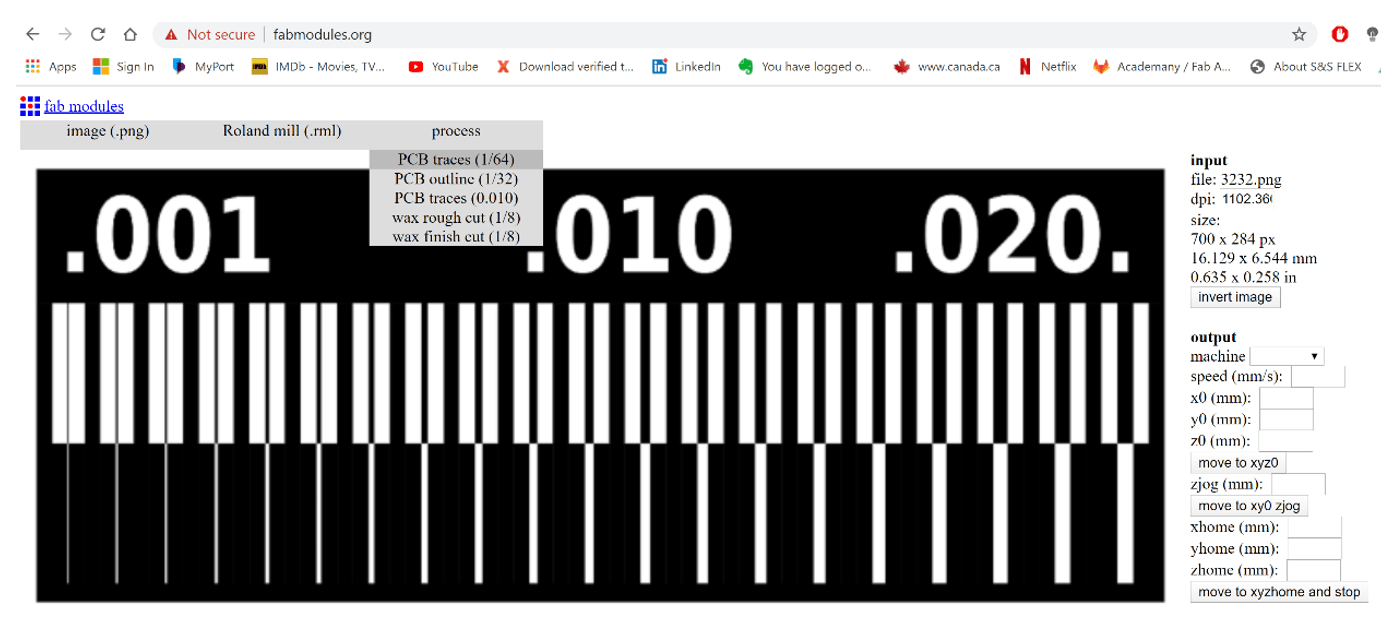
Set the parameters for the trace by changing the values on the output panel on the right as shown below.
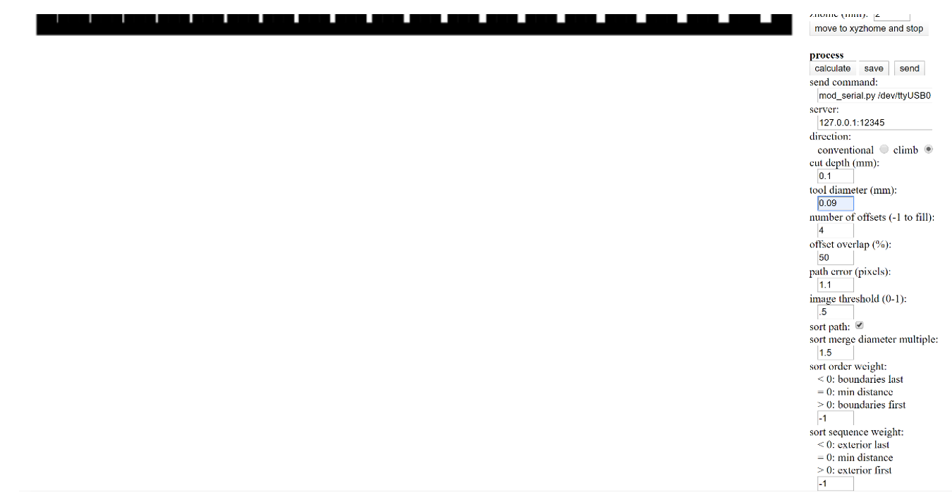
Then click on the calculate button in order to generate the trace for the layout.

Finally, Save the file as .rml format and copy it to the flash memory in order to be imported in to the Roland Mill software.
In order to create the outline for the PCB, click on the image tab and upload the outline image provided by the Fab Instructor to the Fab Module website.

Then the output format for the fab module was defined and Roland Mill was selected from the drop down menu.
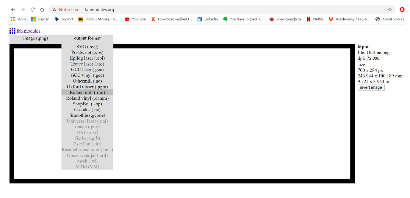
Then define the process for PCB outline (1/32) from the drop down menu.

Set the parameters for the outline by changing the values on the output panel on the right as shown below.

Then click on the calculate button in order to generate the outline for the layout.
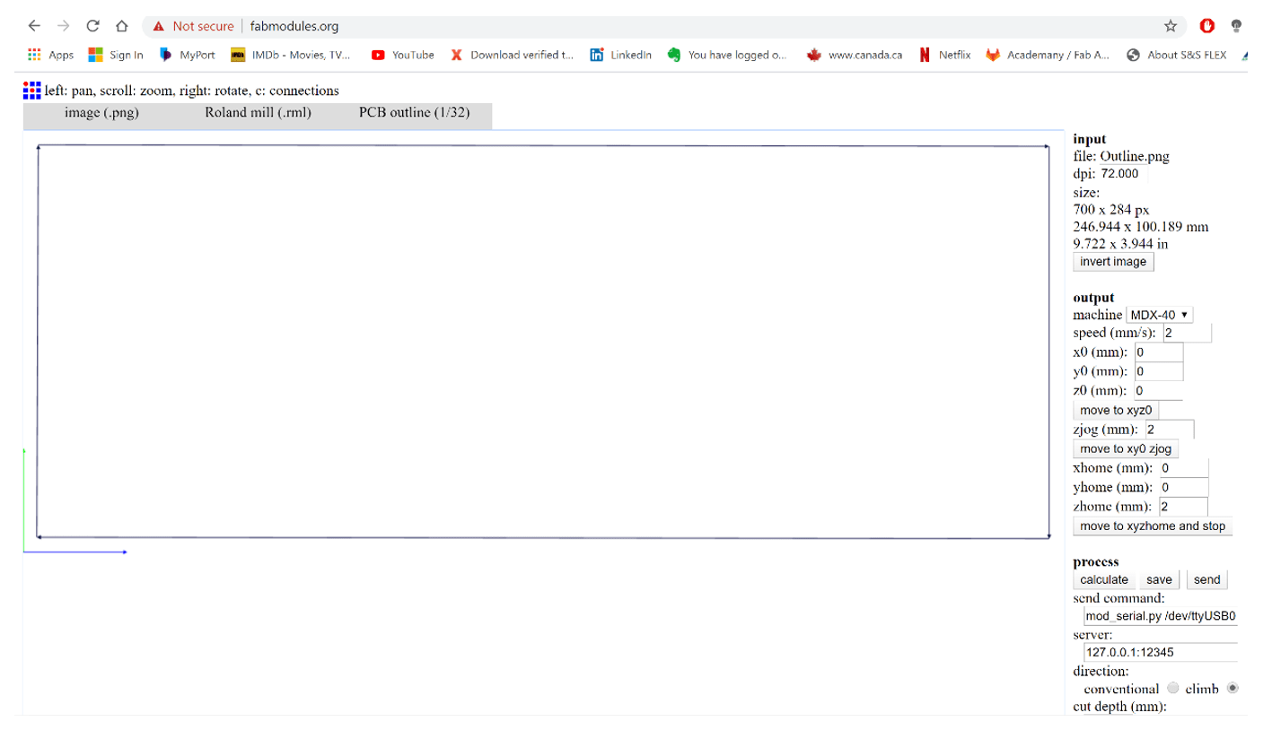
Finally, Save the file as .rml format and copy it to the flash memory in order to be imported in to the Roland Mill software.
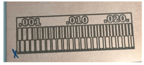
Then Repeat the same steps for printing the PCB using the Roland Mill Machine as mentioned earlier. The final image of the PCB for tolerance is shown below. It can be seen that the accuracy of the machine is quite high as it was able to print small pathways of 0.001mm accurately.


Then Repeat the same steps for printing the PCB using the Roland Mill Machine as mentioned earlier. The final image of the PCB for tolerance is shown below. It can be seen that the accuracy of the machine is quite high as it was able to print small pathways of 0.001mm accurately.