Individual Task: Vinyl Cutting
This task was about using the Viny Cutting machine in the FabLab for printing a design. Initially, the design for this task was downloaded from the internet and was imported into the "Silhoutte Cameo" software. The software was downloaded from the Silhoutte Studio website for free and it can work with Vinyl Cutter available in the FabLab.

Source: Google Images (https://www.pinterest.com/pin/789818853379024180/)
The following are the steps that were taken to cut the desing using the Viny Cutting Machine.
Begin by importing the image file into the working window of the software.
.png)
Then Click on the Trace feature as shown below to outline the contour of the image.
.png)
Then the overall dimensions of the image can be adjusted in order to fit the vinyl paper.
.png)
Then Click on the "Design" option from the top header and set the parameters for cutting the shape using the machine. Also ensure the machine is properly connected to the laptop through the USB cable so that it can be seen available or unavilable for cutting on status bar at the bottom of parameter dialog box.
.png)
Then the vinyl paper was loaded in the machine and the cutting process was initiated from the software.

Since the logo features dual colors, so a black vinyl was loaded onto the machine to cut the black section of the logo.

As seen in the following image the outline of the cut done by the Vinyl Cutter.

Then a transper paper was layed on top of both the cutted vinyls to remove the outline.
Both the outlines were combined to create the image as shown in the original photo.
Source: Google Images (https://www.pinterest.com/pin/789818853379024180/)
The following are the steps that were taken to cut the desing using the Viny Cutting Machine.
Since the logo features dual colors, so a black vinyl was loaded onto the machine to cut the black section of the logo.
As seen in the following image the outline of the cut done by the Vinyl Cutter.
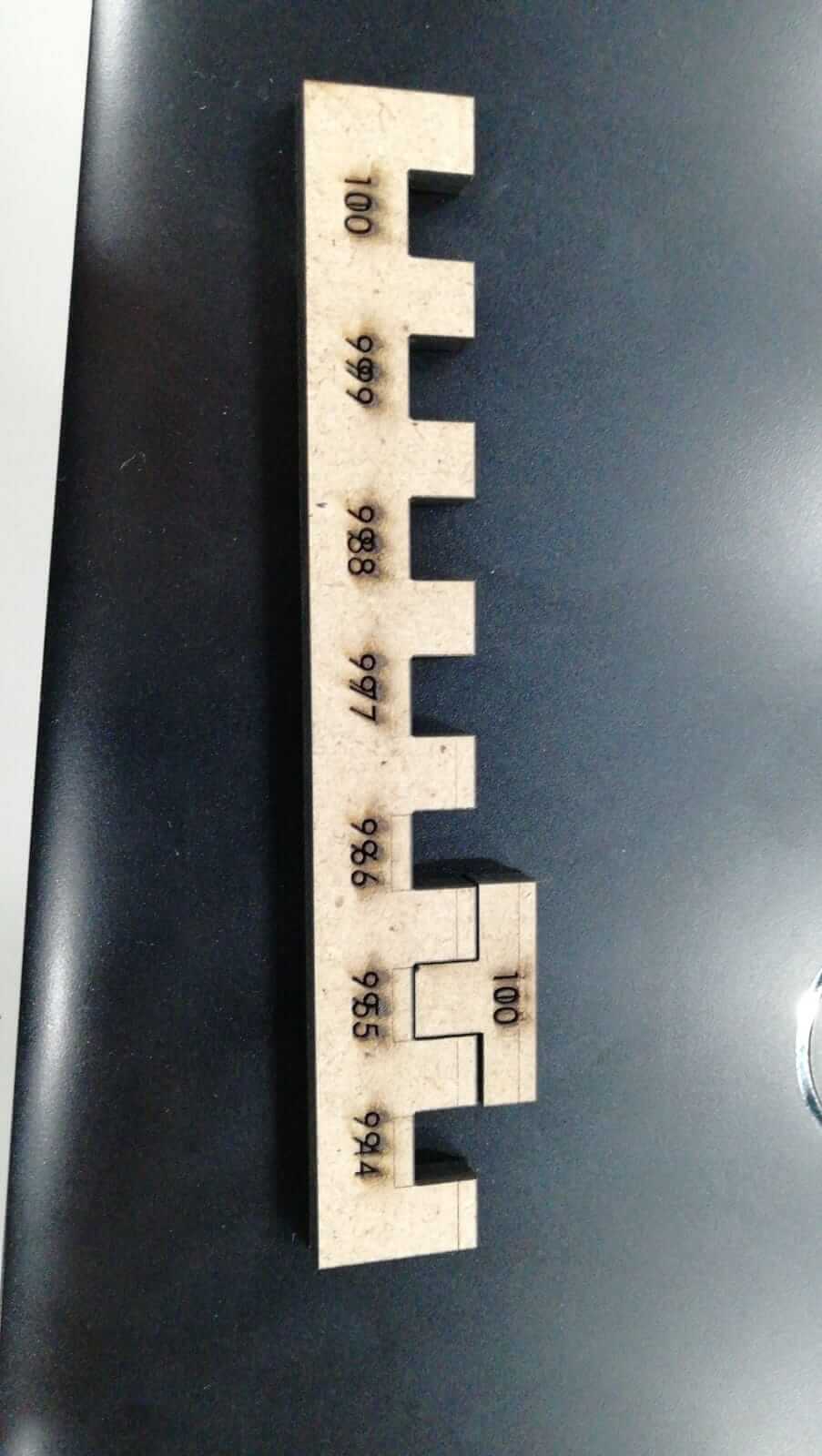
Group Task: CNC Laser Cutting Machine
This task was about using the CNC Laser Cutting machine in the FabLab for determining the tolerance of Kerf while cutting. The kerf is the thickness of the material that burns off when the laser cutter cuts a specimen and each laser cutter has its own kerf limit which is based on the speed and intensity of the laser used for cutting different material samples. The following are the detailed steps done to complete this task.
The kerf model for this task was designed in the SolidWorks software and the distance between each joints was set in the increasing order of 0.2mm.

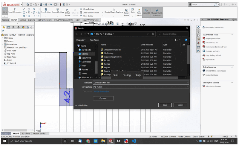
Then the design was saved as DXF file format in order to be readiable by the Laser Cutter Software.
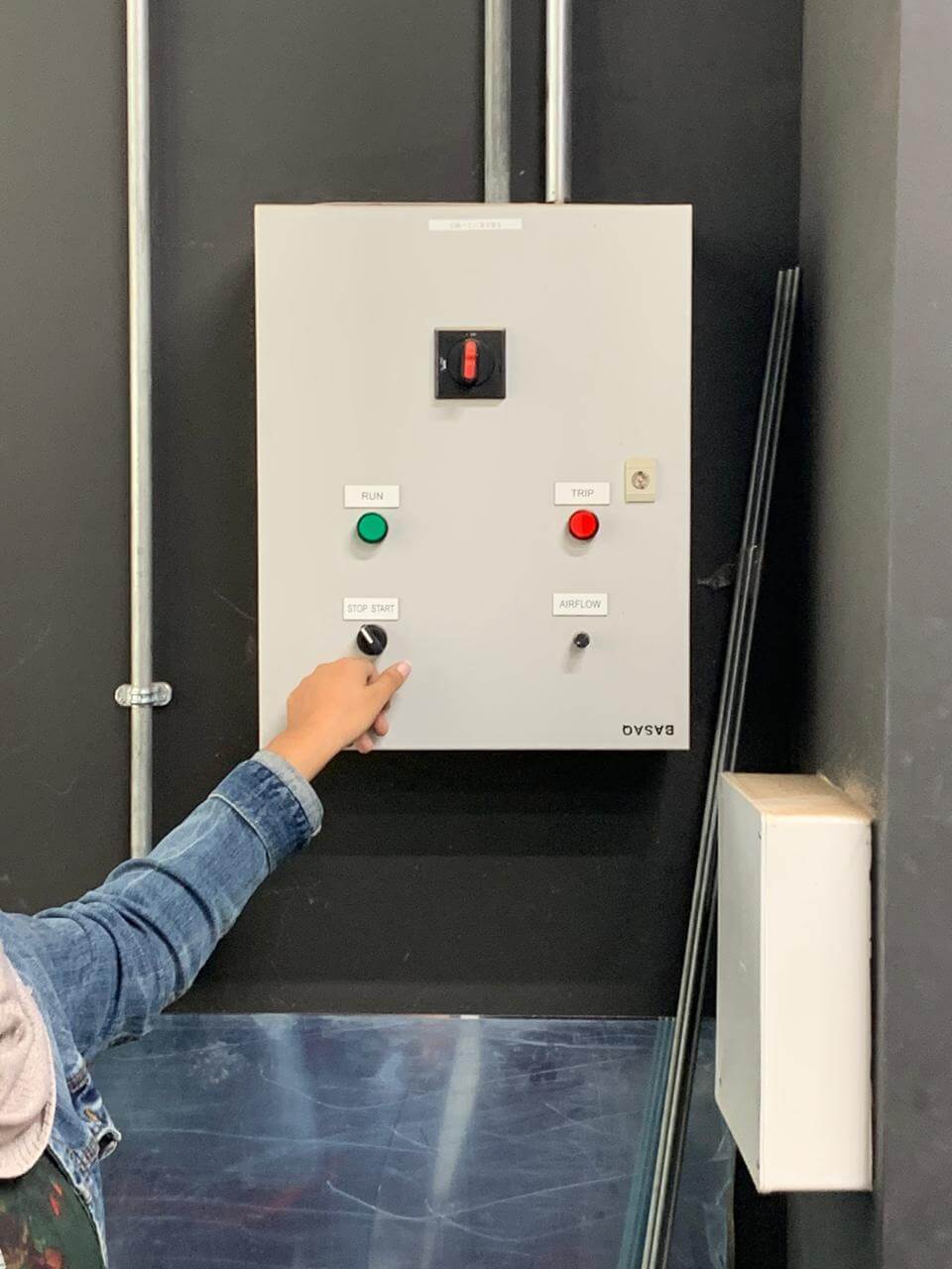
The parameters for CNC Laser Cutter were set. The speed of laser cutter machine was set at 100, power was set at 20 and engrave depth was set at 100. Then the G-codes for the design were generated using the software based on the set parameters and were copied onto a flash memory and was plugged in the CNC Laser Cutter machine to initiate the cutting process.

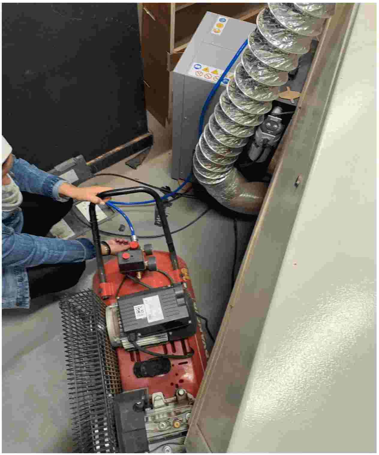
Prior to cutting process, the air compressor and draft ventillator was turned ON.
Then the design was cut on Cardboard material.

After cutting the designs, the two samples were interconnected to check the tolerance for kerf.
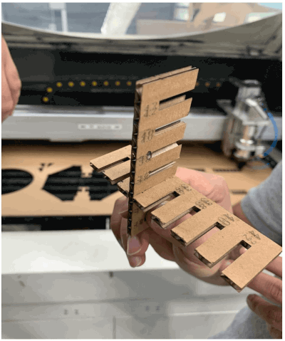
Final Product!
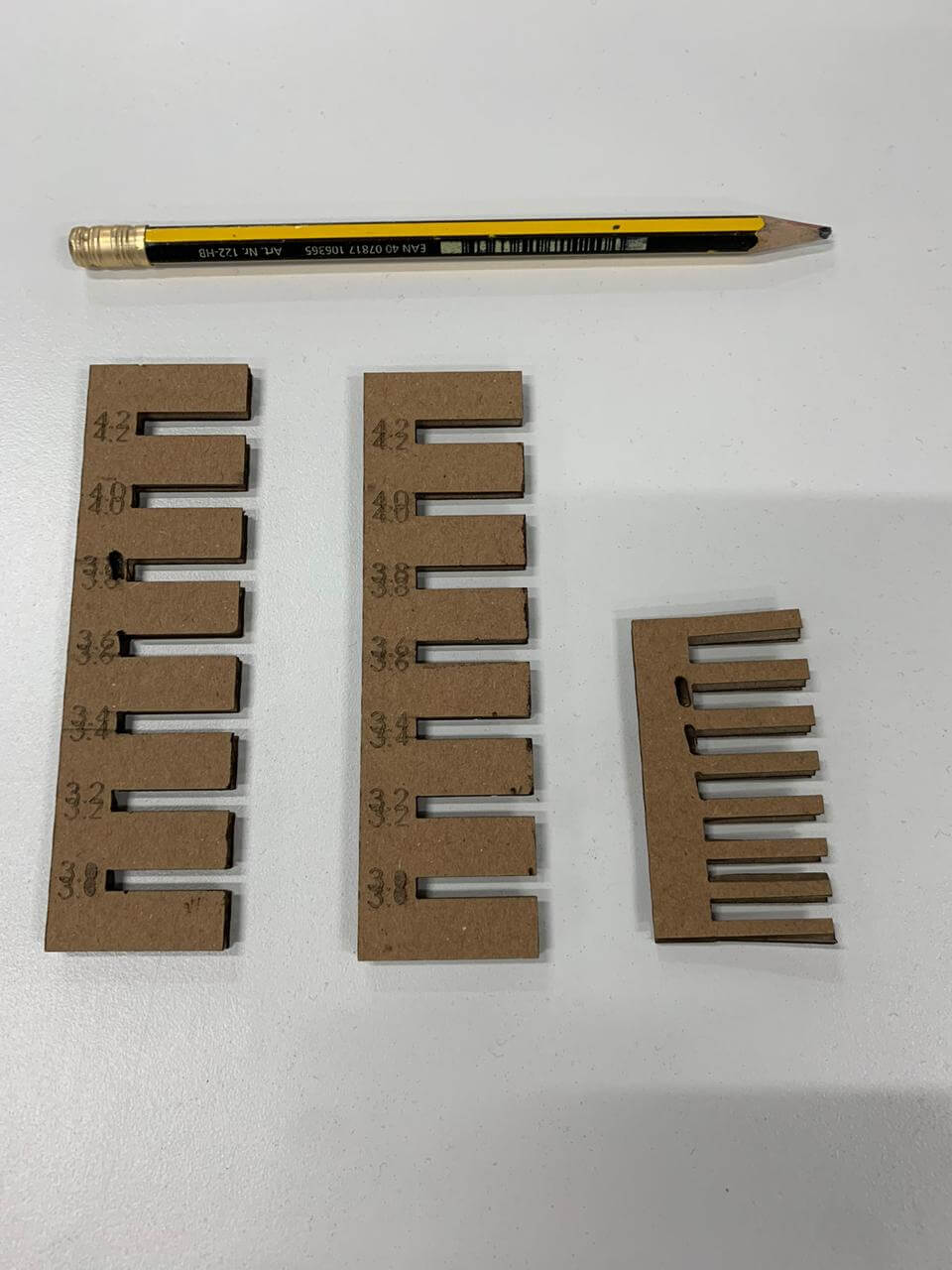
Kerf test on the MDF wood done by another colleague using the same CNC Laser Cutter machine in the FabLab.