machine design
For the machine design assignment, we decided in our group tp build a hot-wire foam cutter. We wanted to design it in such a way that the machine could be partially disassembled easily for transportation, and so that two of the three dimensions could be adjusted easily for different sizes of projects, with the primary axis being easy to swap out for a theoretically infinite working volume.
overview
The machine is built from two mirrored halves that are nearly identical mechanically, each consisting of two linear movement stages. The first stage consists of a sled rolling on top of aluminum extrusion using V-wheels. By swapping out the extrusion for a longer piece, this axis can be adjusted to any length for large-scale work.
The second stage consists of a lead screw driven by another stepper motor, as well as two stabilizing rods. A platform rides vertically on the two rods using nylon bushings and the lead screw. The whole assembly is mounted on top of the first stage.
The two halves can then be connected parallel to each other using more pieces of aluminum extrusion that join the two first stages at either end. By driving the two halves in tandem, any suitable 2d shape can be cut out of the stock as a straight prism. However by driving the two halves differently, the wire can be moved out of its horizontal position and more interesting shapes such as cones and other shapes with draft angles can be produced.
BOM selection
After we took some time to look through the materials we already had in the lab, I was tasked with creating an initial BOM and rough mechanical design to get us started. After some research I decided on using Openbuilds V-Slot aluminum extrusion. I chose these parts because they are well specified, easy to get a hold of in the EU, and available in a wide range of sizes.
I decided to use 40x40mm extrusion for the long rails of the first stage, which have to carry the largest (moving) load. The wider top is also important to give the sled a bit more lateral stability to prevent it wobbling or bowing under the moment of intertia of the second stage resting on top of it. Having the sides be 40mm (two units) wide also gives us two V-Slots on each side, so that we can position both wheels as well as a rack or belt for the actuation there.
The sled consequently is constructed out of a 250mm length 20x40mm extrusion piece. The sled matches the width of the first stage and the slots around it can be used to mount the two stepper motors, wheels and the secondary stage to it in a more or less modular fashion, which makes iterating on the design easier.
Each sled rides on four V-Wheels that clamp down on the 40x40mm extrusion below it from the sides. I also ordered three pieces of 20x20mm extrusion to connect the two halves of the machine together.
mechanical design - stage 1
Our first idea for the stage 1 automation was to use one of the NEMA17 stepper motors we found to drive a pinion gear riding on a rack mounted in the upper slot of the base extrusion. I designed and 3d printed a motor mount to attach the motor on top of the sled horizontally, while Luisa designed two wheel mounts to allow the sled to ride on the extrusion:
Our instructor noted at this point that the the distance between the motor shaft and the V Slot would lead to a very high gear ratio and a mechanical advantage that would not allow the motor to move the sled reliably under load, if at all.
Following this realisation we redesigned the first stage assembly completely: We temporarily used only the front screws of the motor mount to attach the motor vertically on the shorter front face of the sled, so that the motor shaft was now in the same plane as the first slot of the extrusion underneath. We then attached a small pulley to the motor shaft and added a GT2 belt running in the V-Slot underneath the wheels. This way the wheels keep the belt straight along the extrusion, before it comes outside to wrap around the pulley, ensuring a good contact angle. Using this design, the motor could move the sled easily, but the motor mount and attachment was not stiff enough in this temporary configuration.
Since my team members had had less experience with parametric CAD and CAM at this point, I redesigned the motor and wheel mounts in Fusion 360 while using the opportunity to demonstrate the Fusion CAM module.
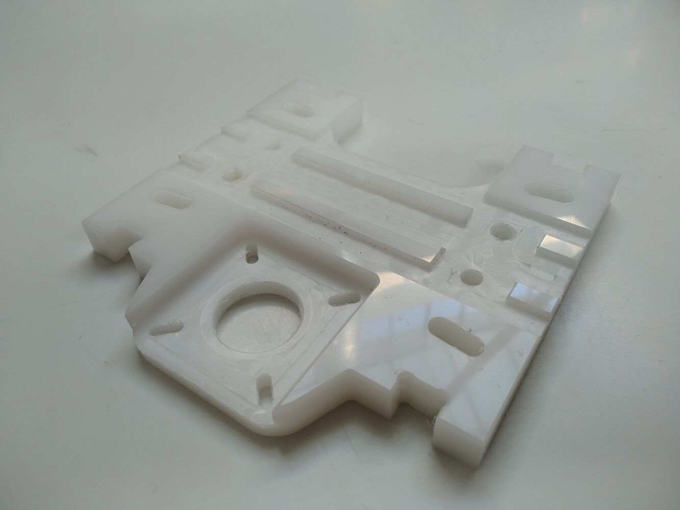
We then started to machine the top plate of the new design out of POM (Delrin) on the ShopBot and verified the motor fit.
electronics
In the group I was elected to be responsible for electronics and software. In the lab, we found four NEMA17 stepper motors that were a good fit for our project. Although I was planning to use a RAMPS board that we also found for the final assembly, I wanted to drive a stepper motor directly first to understand what it would take to create a custom board for this purpose.
I found a Pololu A4988 stepper motor driver (clone) and a corresponding breakout board that made testing the motors very easy. The breakout board has a connector that the stepper motor’s four-pin connector plugs into. There are three dip-switches that can be used to set the microstepping, which I set to the maximum (16x microstepping).
The board then needs to be connected to power (5V, GND and VIN on the Arduino Uno I was using, which needs to be connected to a 9V power source). Then the three signal inputs (E, D, S) can be hooked up as well. I connected the inverse enable input to GND to permanently enable the driver, and hooked up D and S to two digital pins (2 and 3). At this point it is enough to set the D pin to the desired direction and toggle the S pin on and off, like in this example from makerguides.com:
/*Example sketch to control a stepper motor with A4988 stepper motor driver and Arduino without a library. More info: https://www.makerguides.com */
// Define stepper motor connections and steps per revolution:
#define dirPin 2
#define stepPin 3
#define stepsPerRevolution 200
void setup() {
  // Declare pins as output:
  pinMode(stepPin, OUTPUT);
  pinMode(dirPin, OUTPUT);
}
void loop() {
  // Set the spinning direction clockwise:
  digitalWrite(dirPin, HIGH);
  // Spin the stepper motor 1 revolution slowly:
  for (int i = 0; i < stepsPerRevolution; i++) {
    // These four lines result in 1 step:
    digitalWrite(stepPin, HIGH);
    delayMicroseconds(2000);
    digitalWrite(stepPin, LOW);
    delayMicroseconds(2000);
  }
  delay(1000);
  // Set the spinning direction counterclockwise:
  digitalWrite(dirPin, LOW);
  // Spin the stepper motor 1 revolution quickly:
  for (int i = 0; i < stepsPerRevolution; i++) {
    // These four lines result in 1 step:
    digitalWrite(stepPin, HIGH);
    delayMicroseconds(1000);
    digitalWrite(stepPin, LOW);
    delayMicroseconds(1000);
  }
  delay(1000);
  // Set the spinning direction clockwise:
  digitalWrite(dirPin, HIGH);
  // Spin the stepper motor 5 revolutions fast:
  for (int i = 0; i < 5 * stepsPerRevolution; i++) {
    // These four lines result in 1 step:
    digitalWrite(stepPin, HIGH);
    delayMicroseconds(500);
    digitalWrite(stepPin, LOW);
    delayMicroseconds(500);
  }
  delay(1000);
  // Set the spinning direction counterclockwise:
  digitalWrite(dirPin, LOW);
  //Spin the stepper motor 5 revolutions fast:
  for (int i = 0; i < 5 * stepsPerRevolution; i++) {
    // These four lines result in 1 step:
    digitalWrite(stepPin, HIGH);
    delayMicroseconds(500);
    digitalWrite(stepPin, LOW);
    delayMicroseconds(500);
  }
  delay(1000);
}
It’s also necessary to set the current limit correctly using the trimmer potentiometer on the motor driver module. The guide linked above contains a good section on this topic. In my case I experienced some issues here because the cloned driver board I was using had a trimmer potentiometer with an inverse polarity to what I expected from reading up online, which lead to some confusion initially.
software
My plan for the control software was to use Inkscape as the CAM tool. Inkscape has many tools for vector editing, is scriptable in Python and outputs SVG, which is (when constrained to a specific subset) easy to parse.
The idea was to draw the toolpath for the two halves individually, so that the X and Y coordinates of the toolpaths would directly correspond to the movement along the two axes of each half. But the XY positions of each half alone are not enough to fully specify the toolpath, it is also important to know where the two halves are at each point in time relative to each other, since this is what ultimately decides on the draft angle. My idea was to represent this information using a third layer of lines, each of which represents a single moment in time and connects one vertex from the left and right path respectively:

files
- Arduino Sketch (see above)
Motor Mount.ipt(old motor mount in Inventor format)Motor Plate.zip(new motor/wheel mount in Inventor format)