molding and casting

I want to try making custom hexagonal keyboard caps for my keyboard computer final project. I am not certain that I want to use them in the build, but it is an interesting possibility to explore. Using a hexagonal tiling, the keys can be staggered more densely along the horizontal axis, to make it easier to reach more keys with one finger.
cad
I started by designing the part (positive) itself in Fusion 360.

I took some dimensions from the keycaps I got from gboards.ca, and also used a lot of information from the technical drawings of the keyswitch provided by the manufacturer, as well as some drawings of other keycaps I found on AliExpress.


The keycap wasn’t too hard to model, but due to the small size it will be quite hard to manfacture. The “feet” that press-fit into the keyswitch have a width of only 1.2mm, which is very small for most of the router tools we have in our fablab. Since by milling I cannot manfacture 90° convex corners, I changed the shape of the press-fit “feet” from an X-like section that is thicker at the ends to the opposite, with a single thicker protrusion in the middle of each side. The protrusion is thicker than the spec, which will hopefully provide the right amount of friction for the fit.
After modelling the keycap itself, I imported into a new Fusion document for the mold. I then constructed a plane that splits the part in half and added a stock block symmetrically around it. The positive component and the main runner are then subtracted from the stock, after which the mold is split into two pieces along the plane. I then added two keys, which are added to one of the halves and subtracted from the other.
It’s important to fillet all edges on the keys so that they will actually fit after machining with a round bit. I also added fillets on other sections of the keycap itself, also where not aesthetically necessary, to ease the movement of resin and air bubbles.
On my first attempt, the main runner started with a funnel and lead into one of the top corners of the hexagon. I used a single vent at the highest point of the mold:

When I showed the mold to Tiziano, he explained to me that in many cases it is better to have the runner feed into the bottom of the part, so that the air is forced upwards and out by the material being pushed in. Antonio and him also agreed that the two holes for the feet of the keycap would be very tough to get out, since they are essentially dead-ends that easily trap air. Because of this, using vacuum to force the air out is necessary, especially on a part this small. With this feedback I first created the following version…

…before moving on to a much more robust design:

In the last version, I turned the mold 90° to have the main runner and the vents normal to the split plane rather than lying in it (again a very welcome suggestion from Tiziano). This way many little vents can be spaced equally and densely around the part, making it much easier for trapped air to escape. Crucially this solution also allows adding vents inside the feet-holes, which are still the trickiest part of the design. The main runner was designed to fit a syringe end in order to inject the resin in with some pressure, before widening into a sort of wedge / loft shape that touches on the mold core in a long thin section that should be easy to trim off after demolding. However I made an amateur mistake and confused diameter and radius in the corresponding sketch, so that the main runner turned out to be twice as large as it should be. This will be fixed using some silicone or similar when I do the molding, or whenever I mill another mold.
cam
I used the manufacturing module of Fusion 360 to create the toolpaths for milling. It seems like a very good choice, since it is very robust and capable and integrates a very powerful simulation that also helps detect collisions.
Here is the general workflow I followed:
- create a setup
The setup contains some general information, such as stock size, origin, etc. - model the tools you want to use
You may already have a library of tools in your fablab. You can also add tools as you go and set up your operations. - add & generate operations
There are many different strategies and parameters to adjust for each situation, so you will want to create individual operations for specific features of your part. - simulate the operations
The simulation can help you spot mistakes such as features that are left out as well as collisions. It’s also useful to find parts to optimize further. When simulating, I always turn on “Stock Simulation” and “Stop on Collision” to have Fusion 360 inform me about potential problems with the toolpaths. It’s also nice to make the stock transparent if performance allows it. - post-process the toolpaths
This converts the toolpaths from Fusion’s internal format to a format understood by the exact machine you want to use.
The order here is only a rough guideline of how the steps relate to each other, but of course the workflow is not that linear - I started with one setup, one tool and one operation, adding individual pieces as I found them to be necessary.
stock and setup
The setup contains answers to these questions:
- which bodies/components of the design should be manufactured?
- what are shape, size and location of the stock to mill?
- where/what are the origin and orientation of the coordinate system?
I created two independent setups in order to be able to zero efficiently and accurately after tool changes. Both setups share the same stock dimensions and location and both setups use both mold bodies.


The first setup is zeroed on the center of the top surface of the stock. This position is easy to determine physically by tracing lines from the four corners of the stock.
The second setup shares the same XY position, so that after milling using the previous setup, I do not have to re-zero them and stay perfectly accurate. The Z axis however is re-zeroed on the now finished top surface of the mold, which is more accurate than zeroing on the wooden sacrificial layer.
tool selection and modelling
With the tool selection and toolpath generation there is a sort of chicken-and-egg problem: How do I know which tool to use before I choose what operation to do, and how do I choose what operation to do without knowing what tool I can use? Here it helps having somone with some experience to share. Alberto picked out a flat 3.175mm endmill as a good starting point for roughing operations, and for the detail work I found that the smallest mills we had (1mm diameter) were going to be necessary for the details.
In the end I settled on using the following four tools:
- Tool 1 (T1): 3.175mm Flat Endmill
- Tool 2 (T2): 1mm Ball Endmill
- Tool 3 (T3): 1mm Flat Endmill
- Tool 4 (T4): 1mm Drill
Modelling them in the Fusion 360 tool library was pretty straightforward. Here are the feeds and speeds I used (spindle in rpm, feed & plunge in mm/min):
| tool | spindle | feed | plunge |
|---|---|---|---|
| T1 | 12000 | 700 | 200 |
| T2 | 12000 | 300 | 140 |
| T3 | 12000 | 300 | 140 |
| T4 | 5000 | - | 200 |
The lead-in and lead-out feedrate were set at about 70% of the cutting feedrate while the ramp feedrate was set at about 50% of the plunge rate.
toolpaths
To create a toolpath, first the strategy needs to be chosen. There are some very specific strategies built into Fusion, but for me as a beginner the most useful ones where the more general ones: mostly 3D Pocket Clearing, 2D and 3D Contour, and 3D Steep and Shallow.
After creating an operation, an overwhelming amount of settings is available. It took me a while to become comfortable with the many tabs and options (and optional options), hopefully this overview can help you:
tool
Here you simply select the tool you want to use. I wouldn’t change the other options here unless you have a specific reason, it’s easier to change the feeds and speeds in the tool model and have them automatically apply to all related operations that way.
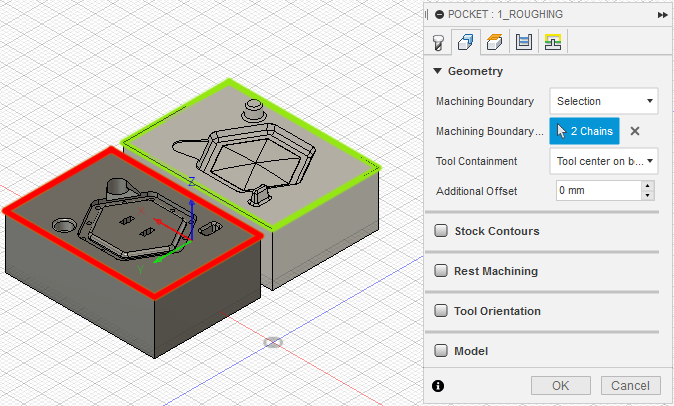
geometry
There are two main categories in Fusion 360: 2D and 3D toolpaths.
The 2D toolpaths generally have you select a 2D shape or area and then work on that area taking into consideration only this shape and the heights and other options you specify. So if you select a flat surface that has a protruding feature attached to it, you need to explicitly exclude that feature or the toolpath is going to ignore and cut right through it.
The 3D toolpaths on the other hand take the full 3D model into account. They still have you select a 2D area in which they should operate (the “Machining Boundary”), but you can also choose “Bounding Box” or “Silhouette” to machine the complete part or stock in simple cases. It’s also possible to choose whether you want to machine only inside the boundary (e.g. example to finish the “floor” inside a pocket that was already roughed out), with the tool centered on the boundary (e.g. to fully face off a surface) or with the aligned to the outside of the boundary (e.g. to fully machine a chamfered feature).
heights
In the heights tab the “top” and “bottom” heights are usually the only parts that have to be adjusted. Operations only machine between these two, and they may be set to (or with an offset from) the model or stock heights as well as a specific selected face.
There is a big difference between multi-pass operations like Pocket Clearing and finishing operations like Scallop: Pocker Clearing will machine the whole volume between “top” and “bottom”, while Scallop will only machine the model surface inside that volume. This has two consequences:
- When you use a clearing operation, but some material has already been removed, either set a custom height or use the “Rest Machining” setting in order not to spend time cutting where the stock has already been removed.
- When you use a finishing operation, make sure that there is only a thin layer of stock left that the tool can handle. Usually this means first using a roughing operation with the “Stock to Leave” setting.
In either case you should be able to use the simulation to find and fix such problems.
passes
The passes tab is very specific to the strategy and usually sets parameters like stepover and stepdown. On 3D operations you can also use the “Stock to Leave” setting to stay a given distance away from the surface and leave some material for a later finishing operation.
linking
The linking tab determines how the tool moves between multiple passes and at the start and end of the operation.
Fusion defaults to a very slow and “safe” retractions strategy, so in all
operations it’s possible to speed up the process by adjusting that in the
Linking tab. Wherever available I used the “Shortest Path” strategy, or
“Minimal Retraction” otherwise. For some operations it was also useful to
switch the Ramp style from Helix to Plunge where I knew there was only
a small amount of stock left from a previous operation.
Here are all the toolpaths I set up. For each one you can see the strategy I used, a clip of the simulation (with stock simulation enabled) and screenshots of all the tabs/settings in which I made major changes apart from what I already mentioned.
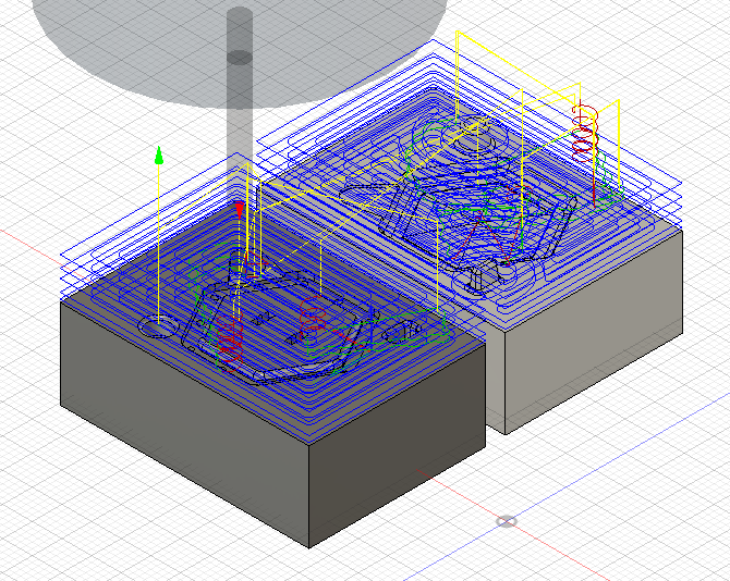
T1_1_Roughing: 3D Pocket Clearing
The first pass is to rough out the flat surfaces on top. I added a considerable
amountof extra stock on top to make sure all my features would fit in it. Since
this is a roughing pass, Stock to leave is enabled and set so that this
operation leaves enough material for the finishing passes to work with.
- Radial Stock to leave: 0.5mm
- Axial Stock to leave: 0.5mm


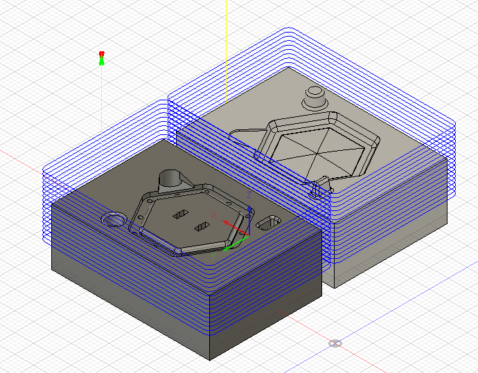
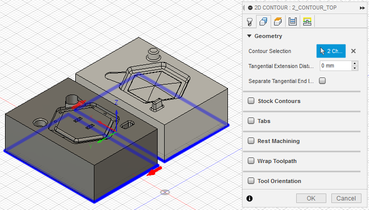
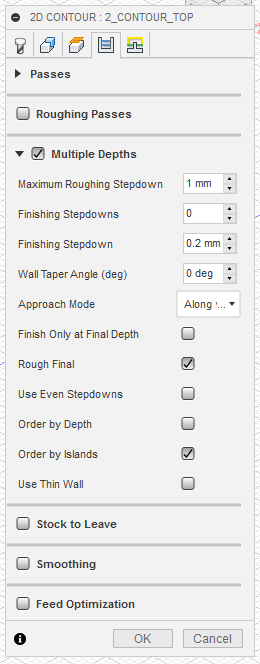
T1_2/3_Contour: 2D Contour
The next two operations countour the two halves of the mold so that they are
easier to cut apart later and to make room for the tool holder in some of the
later operations. Using the 2D Contour operation makes it easy to select the
outlines, but enabling Multiple Depths is required to limit each pass to a
1mm stepdown that the tool can handle. By setting the bottom height above the
stock bottom I left 7mm of stock holding everything together. This part is then
cut on the bandsaw later.
In the following pictures these two operations are shown as one, but they were actually generated as two separate operations, one for each half, to avoid some inefficient ramping where they overlap.
- Bottom Height: Selected Contour - 7mm (instead of tabs)
- Multiple Depths, Roughing Stepdown: 1mm

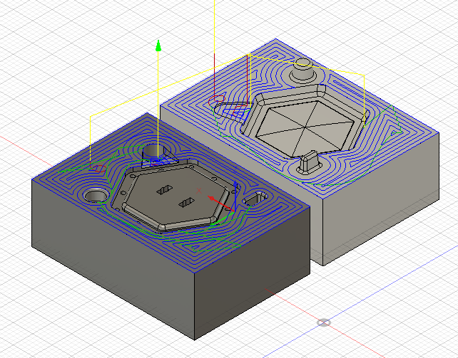
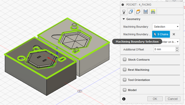
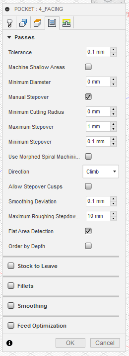
T1_4_Facing: 3D Pocket Clearing
With all the roughing done, it’s now time to finish the top surfaces of the mold. I used another 3D pocket clearing operation, but set the top height so that it would only machine the last millimeter. I also manually set the stepover for a decent surface finish and selected only the flat featureless parts of the mold as the Machining Boundary.
- Top Height: top surface + 1mm
- Manual Stepover: max 1mm
- Flat Area Detection

T1_5_Runner: 2D Bore
For the runner-hole I used a simple 2D Bore operation and adjusted the stepdown. The bottom height is set so that the mill breaks through the bottom of the stock and into the sacrificial layer, ensuring a clean opening.
- Bottom Height: hole bottom - 1mm

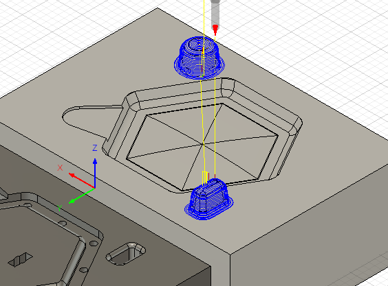
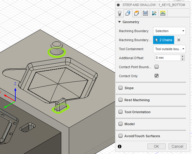
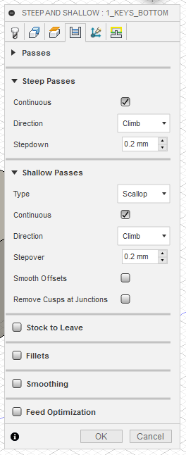
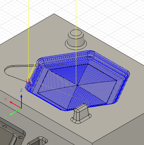
T2_1_Keys_Bottom: 3D Steep and Shallow
The keys have a shallow top but a very steeply angled side, so the 3D Steep &
Shallow operation is a good fit. Setting the Continous option creates cleaner
toolpaths with fewer retractions for these simple shapes. Since this is the
finishing pass on the keys, I set a low stepover and stepdown.
To fully machine the chamfer, the machining boundary is set at the outermost part of the chamfers and the “tool outside boundary” containment option is used.
- Tool Containment: Tool outside boundary
- Continous (for both Steep & Shallow)
- Stepover, Stepdown = 0.2mm
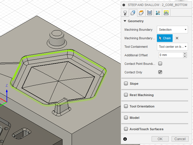
T2_2_Core_Bottom: 3D Steep and Shallow
The top part of the keycap has a slight curvature and many fillets, so the ball mill is a good fit here too. Since the walls are steep, Steep and Shallow is a quick solution here as well.
- Continous (for both Steep & Shallow)
- Stepover, Stepdown = 0.2mm
- Machining Boundary: Open by clicking on boundary, choose alternative
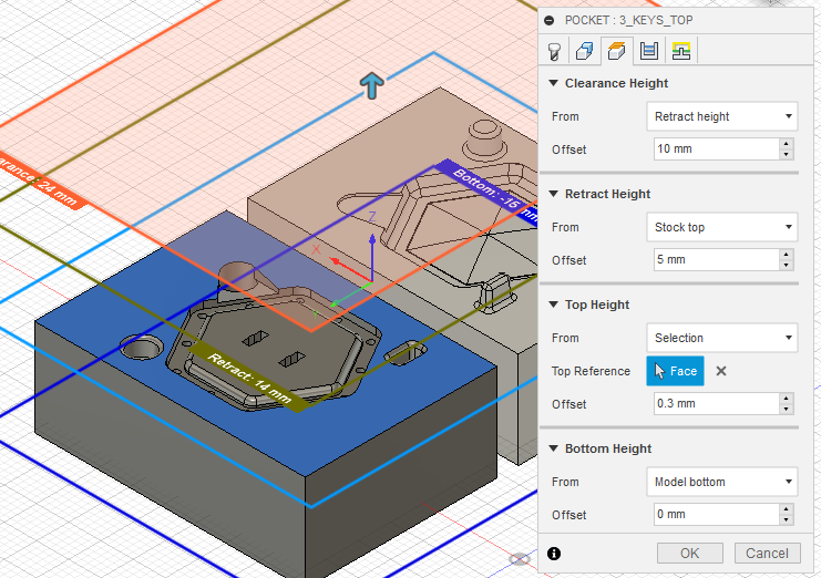
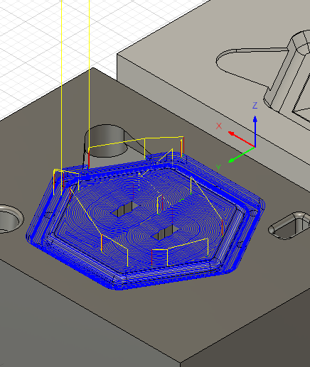
T2_3_Keys_Top: 3D Pocket Clearing
For the negative side of the keys I used a pocket clearing operation with similar settings as for the other part. I had to set the top height to slightly above the start surface of the hole to have the endmill also cut the chamfer.
On this operation I added a Stock to Leave value of -0.2mm for some tolerance
in the key fit. This turned out to be a little much in the end, so I would
suggest either trying a smaller number or removing it altogether.
- Tool Containment: Tool outside boundary
- Top Height: Selection + 0.3mm
- Machine Shallow Areas
- Manual Stepover: max 0.5mm
- Max Roughing Stepdown: 0.5mm
- Radial Stock to Leave: -0.2mm (fit tolerance)

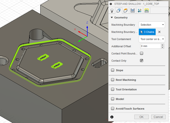
T3_1_Core_Top: 3D Steep and Shallow
Since the bottom half of the keycap is completely flat, I used a 1mm square
endmill here. To get clean walls on the outside, I used the Steep and Shallow
strategy again. I excluded the feet-holes using the Machining Boundary since
these are the trickiest part and require some specific settings.
- Continous (for both Steep & Shallow)
- Stepover, Stepdown = 0.2mm
T3_2/3_Feet: 3D Pocket and 3D Contour
Since the feet-holes are left unfinished by thep revious operation, this now requires two very short passes. The first is a 3D Pocket pass that just clears the last millimeter above the surface. The second is a 3D Contour pass that mills out the slightly concave inside walls of the teeth.
- 3D Pocket:
- Top Height: Top Face + 1mm
- Maximum Roughing Stepdown: 0.6mm
- 3D Contour:
- Maximum Stepdown: 0.6mm
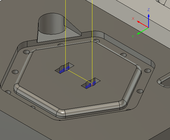

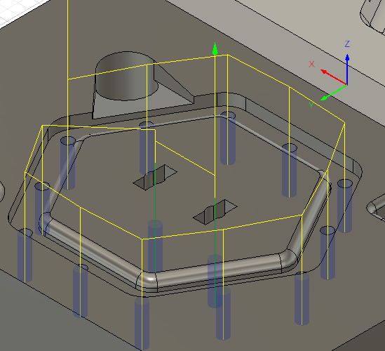
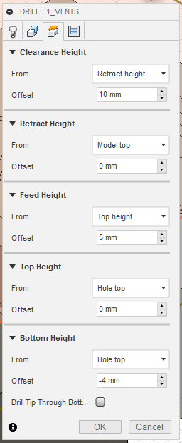
T4_1_Vents: Drill
Lastly, the vent holes are drilled out using a 1mm drill and the Drill strategy. Since the drill tool isn’t long enough to reach through the stock, I set the bottom height to be only 4mm below the hole top, so that the holes instead serve as pilot holes for manual drilling after machining.
- Bottom Height: Hole Top - 4mm (drill to mark only)
post processing
I grouped the operations for each tool in an NC program using the Roland ISO
post preset and gave them sequential names (1001, 1002, 1003, 1004). Like this
I could easily post-process all of them together into a folder and copy it onto
an USB key for milling.

machining
Since the part is very small, I’m using machinable wax, which machines well with small tools. I’m using the Roland MDX-40A desktop milling machine.
I found a block of wax that had two dimensions close enough to the shape I needed, while also leaving enough stock to account for slight misalignment and workholding. I cut a slice of the correct height on the bandsaw, then drilled four holes in the corners on the drill press and carefully screwed it down to a sacrificial wood panel using wood screws and washers to distribute the load more evenly. For cutting and drilling I scribed guides into the wax using calipers.


I clamped the wood layer to the router table and made sure that the stock edges were parallel to the coordinate system by moving the tool very close to the edges of the stock and then along them while paying attention to the gap. After adjusting it a bit this way I clamped the wood down to the router table using five large paper clamps.
I then tested my program by zeroing a distance away from the actual stock and veryifying that the toolpath looked as expected before zeroing again on the actual top center of the stock, which I had marked earlier.
Then I just went through the four NC files I generated earlier, changing tools and re-zeroing the Z axis after each. To zero accurately, I used my phone light at a shallow angle to have the tool cast a long shadow on the perfectly flat wax. This visually elongates the distance between the tip of the tool and the its shadow, making it pretty easy to get decent accuracy.


Since the drill tool wasn’t long enough to reach through the stock without compromising other features, I had to drill out the holes on the drill press using a larger (1.5mm instead of 1mm) drill bit. However the 1.5mm drill was too big to fit into the “feet”-holes, so I instead very carefully drilled from the other side until I reached the smaller 1mm holes from the last pass.

After drilling the holes I unscrewed the block from the wood layer and cut the individual pieces apart on the bandsaw. Here you can see the two parts of the mold snap together and register using the keys:
molding
Since the keycap is a very small part with fine details, I wanted to use a vacuum pump to degas the mold after pouring. We have a vacuum pump in the lab, but no vacuum chamber for regular use. Instead Tiziano suggested to use the steel can of a paint sprayer with a custom lid. I made a quick design for the lid in Fusion 360 and milled it out of thick acrylic on the ShopBot, then cut a matching seal ring out of a thin foam on the lasercutter.

The lid has a hole in the center for a one-way valve from an aquarium shop, which is sealed in place using sealant putty and a groove on the underneath to loosely retain the foam ring. Once the chamber is evacuated, the pressure keeps everything together anyway.

Here is a short clip of a test-evacuation with some water in the chamber. The water is boiling at room temperature, which shows that the pump is working pretty well.
To keep my mold fixed together, I drilled two M3 holes and bolted the two halves together with washers and nuts. I also glued a piece of wood to the bottom to make it stable again. I used some tape around the top of the mold to create a wall to retain the excess resin. This helps evacuate air from inside the mold in the vacuum.

The main runner at the top opens up to accept a small syringe. Since I made a design mistake, I had to use more of the sealant putty here to make the syringe fit snugly.

The resin I used is this clear “Cristal EP” resin. It comes in two parts that have to be mixed in at a 10:4.5 ratio and has a very long work time of ~5 hours and fully sets after around 24 hours. I measured 20g of the first part and 9g of the second part into a small plastic cup and mixed it thoroughly until it seemed fully homogeneous. It turned out later that half of the amount would have easily been enough for a mold of this size. While handling the resin I wore protective gloves and glasses.

I then poured the resin into the syringe, which serves as a funnel and presure-pipe here. The resin immediately began sinking into the mold and came out of the vent-holes smoothly. The mold was already placed in another plastic cup, to make it easy to move it around without coming in contact with the excess resin, and to protect the inside of the vacuum chamber.

After pouring the resin, I moved the the plastic cup into the vaccum chamber and evacuated it with repeated short pulses from the pump until I could no longer see air bubbles coming out of the mold. I then left the mold in the chamber for about half an hour before slowly releasing air back into the chamber, removing the plastic cup and leaving it to cure overnight.

The next day I demolded the part. First I had to trim and break off the excess resin.

Using pliers I could break the nuts and bolts free and remove them.

With a bit of force the two molds came apart with no problems, revealing a great finish on the top surface of the key, and some smaller bubbles encased inside.

Removing the key from the mold completely was a very painfull process though. The vent-holes are very small at 1.5mm diameter, and I had to pry quite strongly using a small drill bit to slowly push out the part piece by piece. It also turned out that the resin had not had quite enough time to set fully, and was still rather flexible, resulting in a completely warped part:

After removing it from the mold, I cut off the vent-tubes and main runner, and put the part back in the mold. I then bolted the mold back together and let it set for another 6 hours. When I opened it again, the keycap had assumed back its original shape and hardened fully:
I’m really happy with the result. The surface finish is great, and the feet fit into the keyswitch well too.
files
- Keycap CAD (Fusion 360)
- Mold CAD & CAM (Fusion 360)
Hex Mold.zip(backup in Inventor format)