output devices
first attempt
I still had some 0.91" 128x32px SSD1306-based OLED displays at home that I never got to try. They are very neat little displays with a flat-flex connector and the control IC (the SSD1306) integrated into the back of the module.
One of the tricky parts of working with OLED displays is that they OLED require a rather high voltage power supply (7-15V) to function. However The designers of the SSD1306 anticipated that these modules may often be integrated in low-voltage digital circuits, so the logic signaling operates at 3.3V, and the IC includes an optional charge pump that can boost voltages between 3.3 and 4.2V up to the required 7.5V. This just requires adding two external capacitors for the pump to use, and enabling the pump in software.
To get this working however, First I had to get the flat-flex connector of the
module hooked up. If I had access to the lab it shouldn’t have been to
difficult to solder it straight to a matching array of traces at the right
pitch, but without tools I had to resort (once again) to enamel wire. See below
I used a protoboard PCB to solder to, and started by sticking both the OLED
module and the protoboard down to my work surface using double-sided tape.
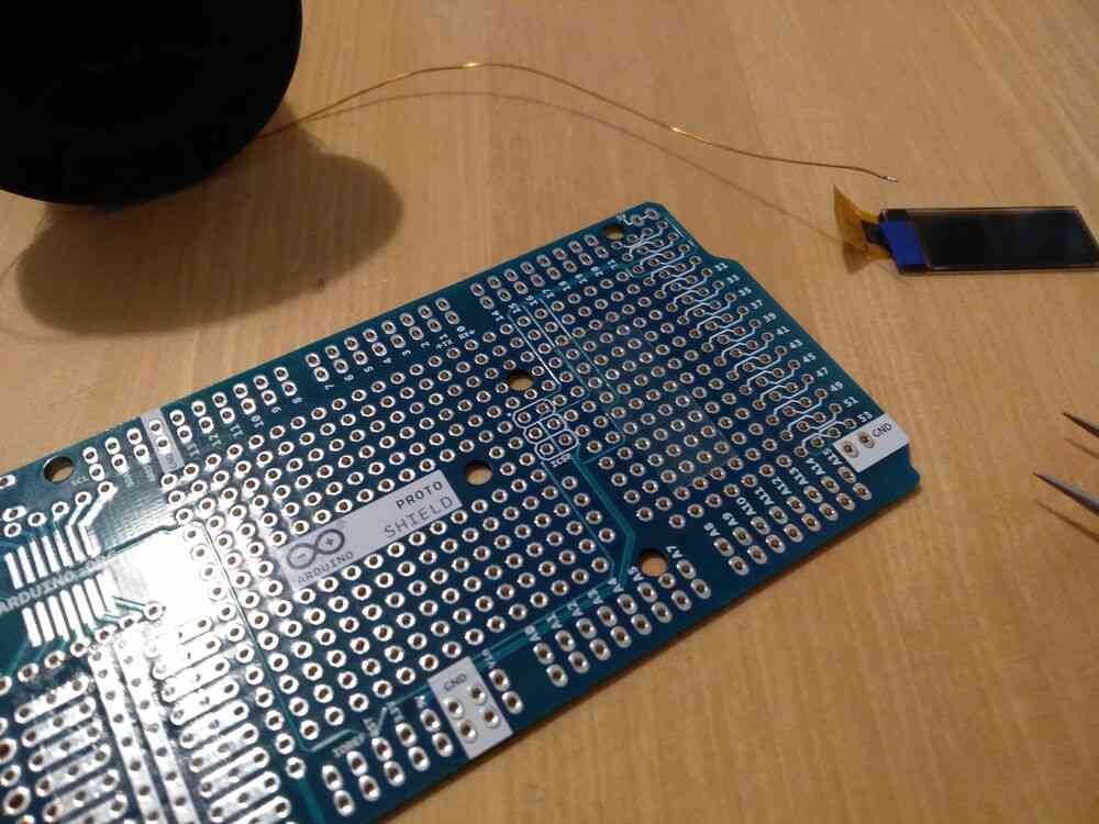
I then started to solder the 27AWG copper enamel wire to the pads on the FFC connector. This task became problematic quickly, as the soldering tip and my precision really weren’t enough to tackle these tight pads, heating one pad often would also heat and detach one of the neighbouring pads. In addition, some of the thin tracks started to delaminate due to the mechanical stress I put on them while verifying the connection was solid, and some even tore off.
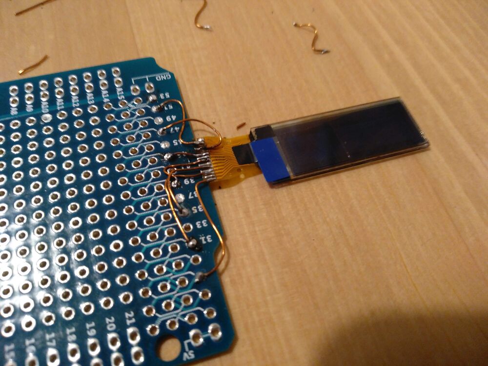
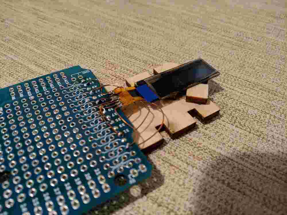
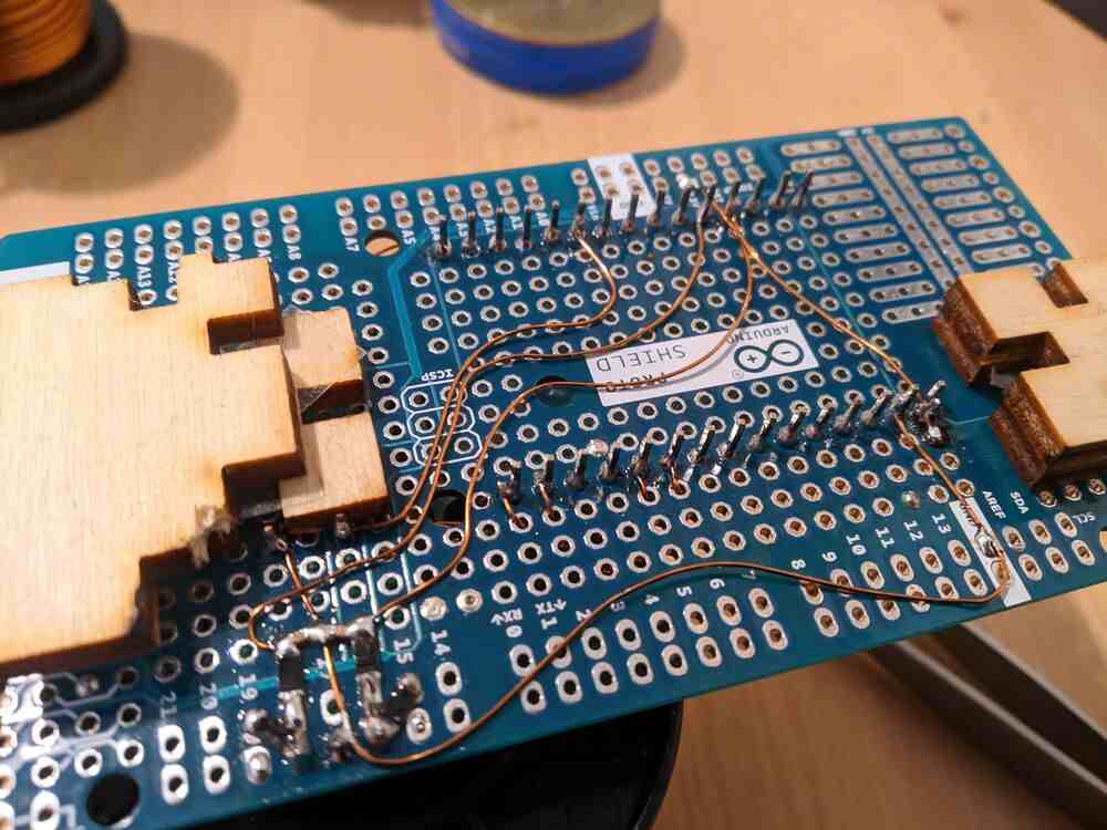
After some head-scratching, I decided to only solder every second pad on the top of the connetor, and to connect the remaining pads on the underside. This worked a lot better. Here is the first completed side:
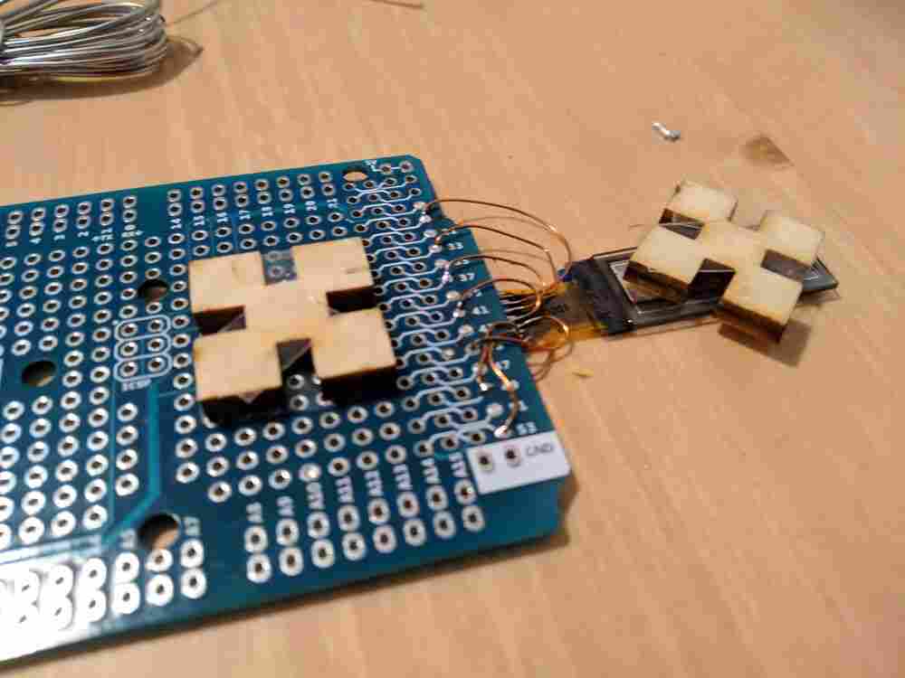
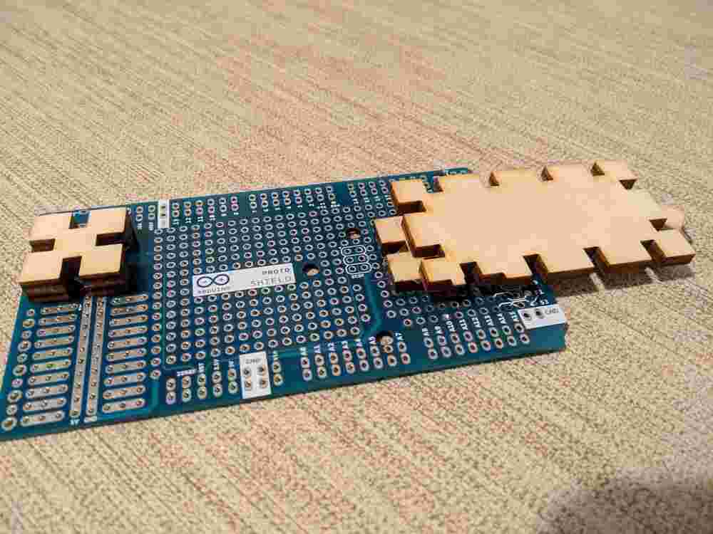
Working on the second side also went well, although the connector was now at a lower height than the PCB, which meant I could only approach the pads from the ‘wrong’ side. Once I connected all pads, I stuck on some scrap lasercut wood pieces on the bottom side of the board that would serve as spacers to protect the rather delicate wiring and provide strain relief for the OLED module tself:
I’m not quite sure if all the pads are well connected, but I guess I will find out when I try this soon. I think if it doesn’t work right away, I might just repeat this exercise with another module now that I have the two-sided trick worked out, or even reuse the wiring and just swap out the module in-place.
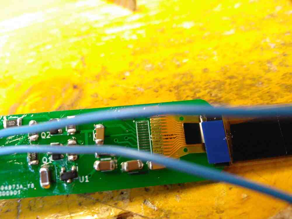
After hooking up the the FFC connector, I added the passives and wiring required as per the reference design in the SSD1306 datasheet (the charge pump example at the very end):
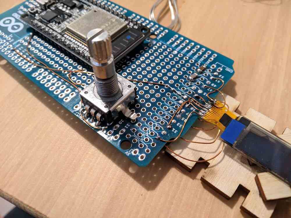
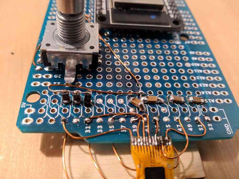
I mounted the capacitors and pull-down resistors at the bottom tombstone-style, which made it very easy to have them all connected in parallel to the GND line.
So, all done right? Well, after taking a break I wasn’t too confident this mess was going to work out after all. In the end I decided to not even try, assuming that an attempt at bringing this up would probably just end in a twelve hours of debugging with no result in sight.
second attempt
Back in the lab it quickly became clear that milling a board at such a tiny pitch just wasn’t feasible. After some deliberation I decided on having a professional PCB fabbed in China. I more or less copied the Adafruit schematic and designed a board slimmer than the one they sell so it would fit into my keyboard’s back bracket. All components are on the front of the board, so that the screen can be glued flush to the back of it. I ordered five boards (the minimum) and a week later these arrived:
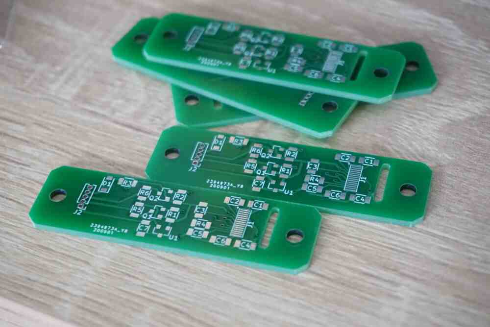
They came out beautiful! After soldering up the first board, I just found a tiny little problem. Can you spot it?
The display just doesn’t fit. Ouch, this hurt a little. When I designed the board, I wrongly remembered the pitch of the FFC connector to be 0.5mm when it is in fact 0.6mm. Handily, there are also no datasheets for the displays, all datasheets I could find document the internal silicon chip and the FFC is just a manufacturing detail.
third attempt
Once I gathered myself again emotionally I took another shot at making a suitable PCB in the lab. 0.6mm is a lot more than 0.5mm after all, no? Milling was still not going to cut it, but Tiziano suggested a different PCB process that he had heard about but never tried. It goes something like this:
- Clean a PCB (thoroughly)
- Coat the surface with a thin layer of spraypaint
- Ablate the paint using a lasercutter
- Etch away the exposed copper surfaces
- Clean off the paint
I documented the process separately here.
Suffice to say this worked pretty well!
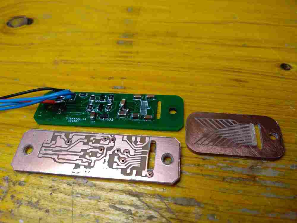
Soldering on the FFC connector was pretty tricky but worked fine in the end. I first tinned the pads on the PCB and the FFC, applied flux and then tacked on the two corners. Then I reflowed all the solder until it seemed evenly and strongly adhered.
After messing around with everything for a day, I managed to bring the board up first from an Arduino and then via a prototype ATMega32U2 board from my final project. However I noticed that the brightness was not constant and would fall off from near full to very low quickly after turning on the display.
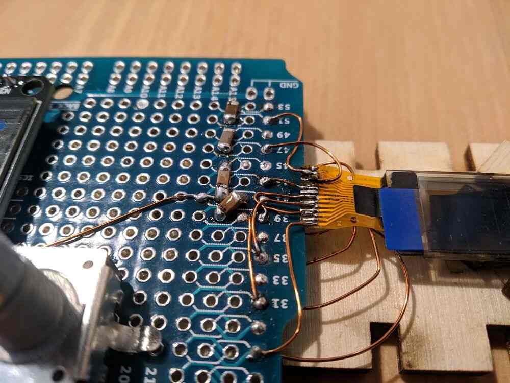
After a lot of hunting I found the problem: the first two pads were shorted because I forgot to move a trace when converting the PCB design from the professionally-fabbed one to a labmade one. The trace from pin 2 to the capacitor marked in the picture below was covered by soldermask on the professional board, but was shorting to the FFC connector on my board.
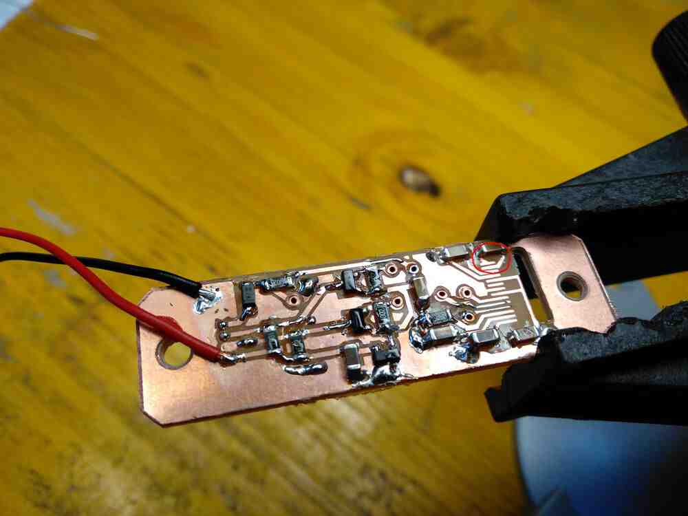
This was shorting out one of the two capacitors powering the charge pump of the SSD1306 oled controller, which caused it to be unable to provide the voltage needed by the display itself.
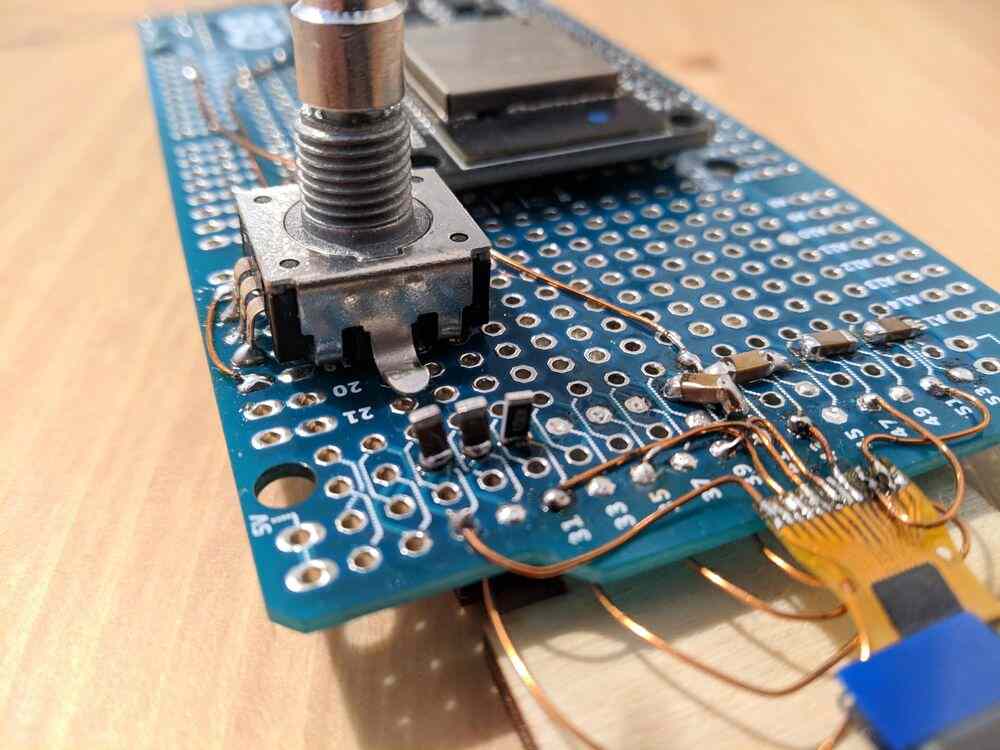
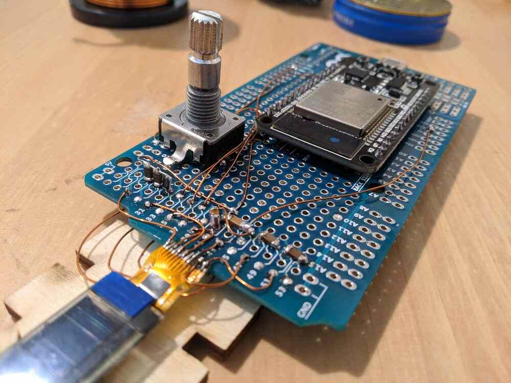
I managed to fix the issue by desoldering the oled display using the hot air rework station, removing that trace entirely, soldering the display on again, and finally restoring the intended connection using copper enamel wire.
This finally brought the display to full brightness, permanently:
Or so I thought. I was really proud of my newly acquired SMT-bodge-fu and excitedly went ahead to try and mount the board in the keyboard shell. I hot-glued the oled to the back of the board, did a test-fit and noticed the position had to be corrected a little. So I broke the hot glue off, cleaned the board and repeated the process. It was still not right, so I did it again…
…and the display didn’t work anymore. I guess that prying it off the back of the PCB the second time I must’ve damaged either the display itself or the FFC.
back to basics
This was the only oled display I had left, and ordering another from China would’ve taken weeks. It was pretty frustrating to go from barely-working to awesome back to completely broken in a matter of fifteen minutes, but once I got over it I decided to search amazon for some other parts and wouldn’t you believe it, I did actually find some completely integrated cheap modules that were the right size and already soldered and working - exactly what I needed, with none of the effort or the pain involved.
It certainly feels like cheating at this point, but after all these ups and downs I really can’t complain.
programming
I did some testing using the Adafruit_SSD1306 Arduino library which essentially abstracts away all of the job. For my real use-case, I needed to run it on an ATMega32U2 instead though.
The 32U2 does not have hardware support for I2C, which is the interface the SSD1306 uses. I found a bit-bang I2C implementation and a minimal SSD1306 lib, but it seems the startup sequence from the lib was written for a different display hardware configuration and didn’t work. Since the Adafruit example was working fine, I ported over their startup sequence, which did the trick.