input devices
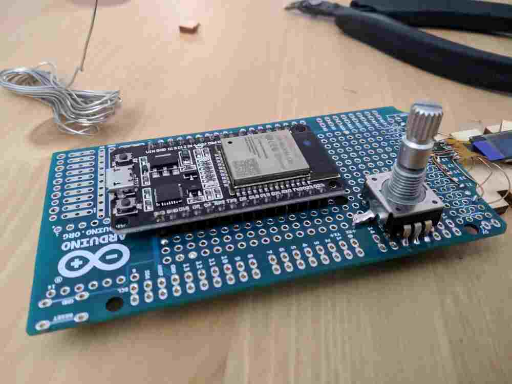
After bringing up the ESP32 dev board itself up successfully, last week, I continued by soldering the encoder and its filtering network to the protoboard. I followed the schematic from the electronics design assignment closely, so that my code for this prototype would transfer directly to a board fabbed later.
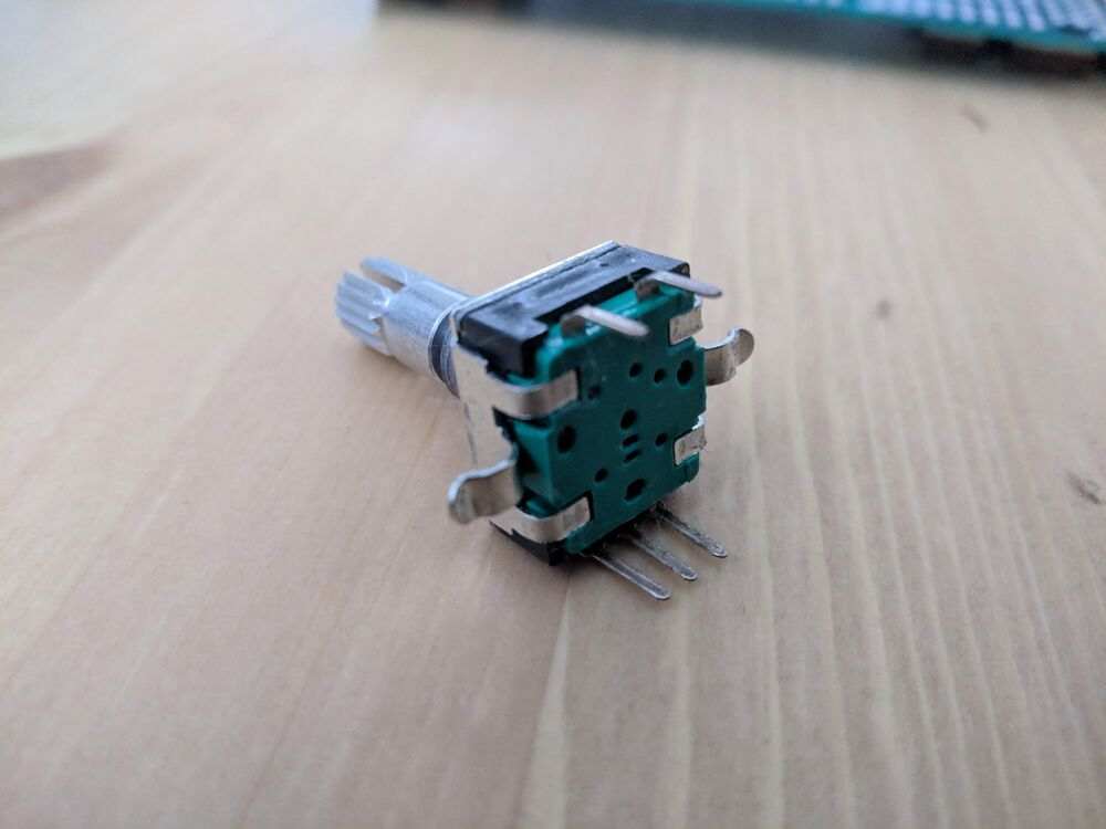
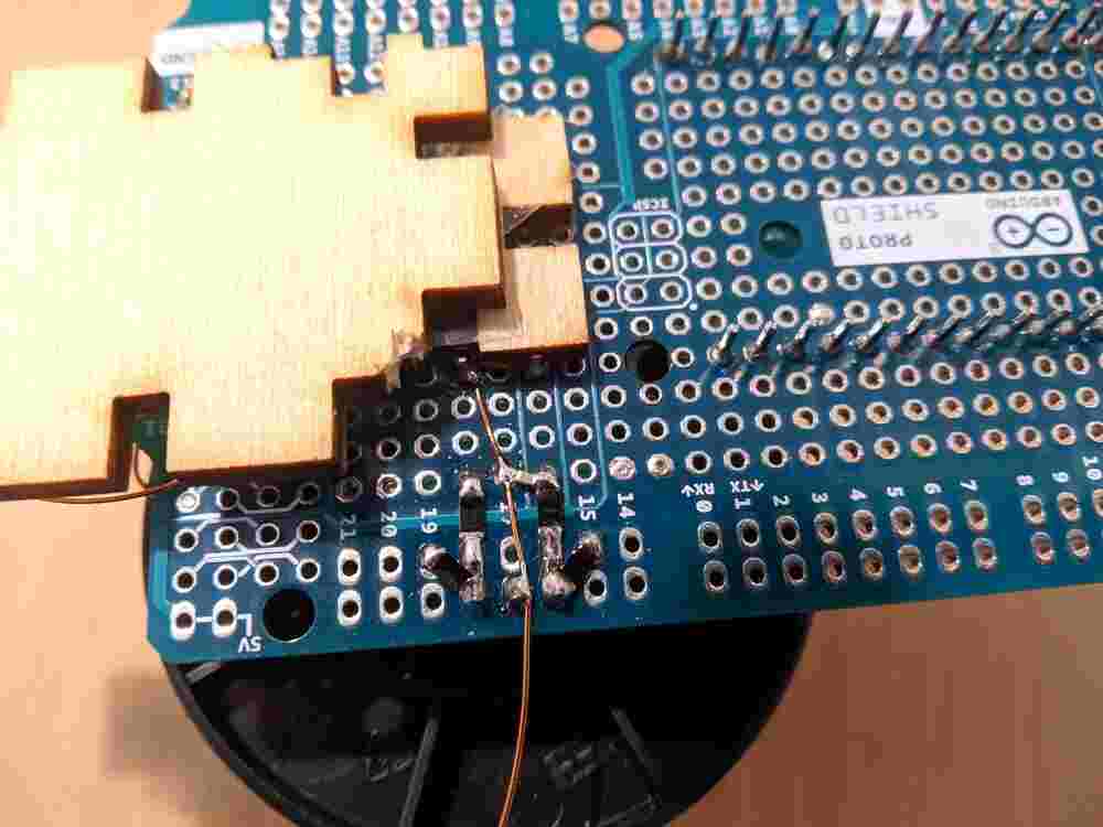
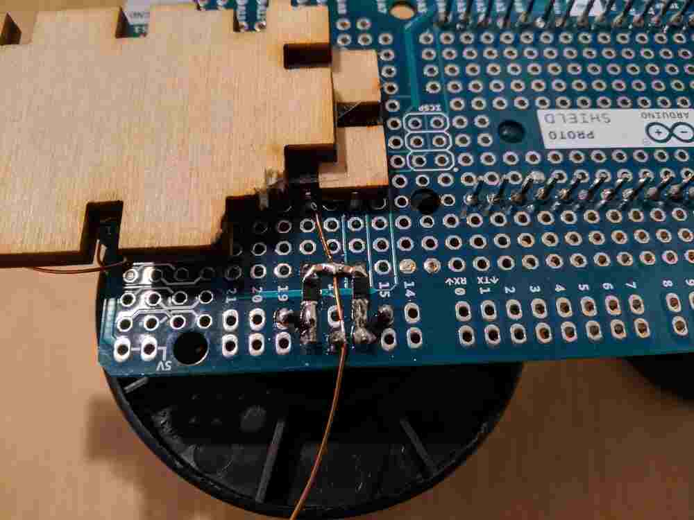
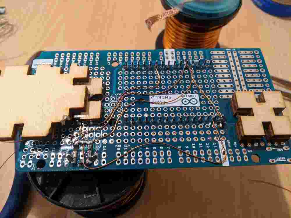
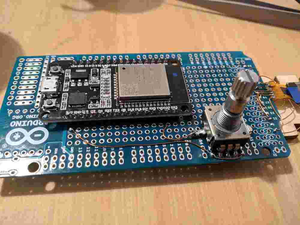
To fit the encoder on the protoboard, I had to bend the two big mechanical mounting pins to the side with pliers. I soldered one of them to a random pad for extra stability, but the five regular pins probably would have been strong enough on their own.
For implementing the capacitive sensing, I looked at the
peripherals/touch_pad_read and peripherals/touch_pad_interrupt examples, as
well as the peripherals/gpio example to get a basic understanding of the
Touch and GPIO APIs, which are also documented here and
here on the Espressif API docs.
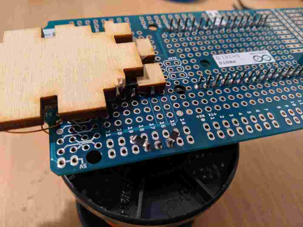
Using the touch_pad_read example, I figured out that I had mis-wired the
mounting pin of the encoder, which I am using for capacitive sensing. I had
wired it to GPIO 22 rather than 27… the silkscreen on this knock-off dev
board is really low resolution. Once it was wired correctly, I saw that the
filtered touch value was resting at around 900 at default settings, and
dropped to a value between 100 and 300 (depending on contact pressure,
humidity…). A threshold of 400 worked very well to detect touching of the
encoder:
I then converted my code to an interrupt-based execution model
and factored the Serial output and LED blinking into its own FreeRTOS Task,
connected by a Queue (like in the gpio example). I moved on to add support
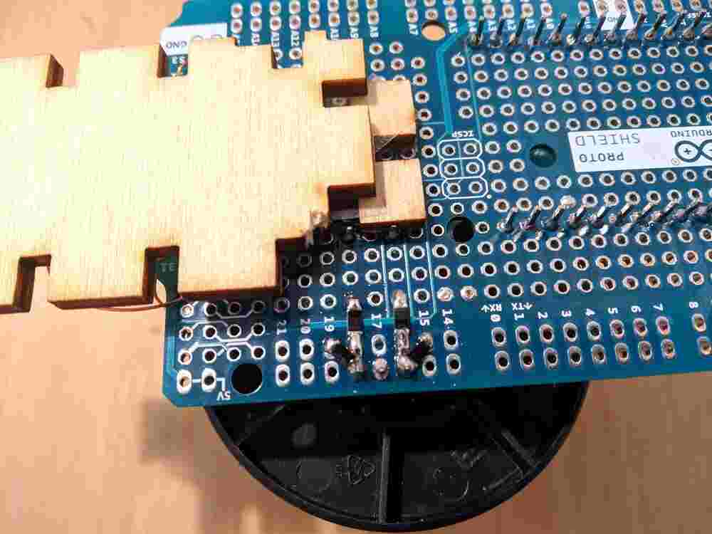
for switch pressing and encoder rotation, but noticed quickly that there was
something very wrong with the encoder pins A and B. I got the switch working
soon, but still don’t know what is up with them - it seems as if both sides
are shorted together and to 3V3? I am still not sure how that is physically
possible, given that they are not also shorted to GND, which is the only shared
node in the filtering network, but I will have to investigate more. I am a bit
skeptical of the resistors I used, because they are unmarked, while the other
resistors (from the same brand) I got in the same order all have their values
marked properly.