over-bed table
CAD
I currently do not own a TV, but have a spare monitor that is easy to move around. I would like to use it as a TV to be watched from the bed, but at the foot of the bed it is too far away to see details at the high pixel density of a PC monitor.
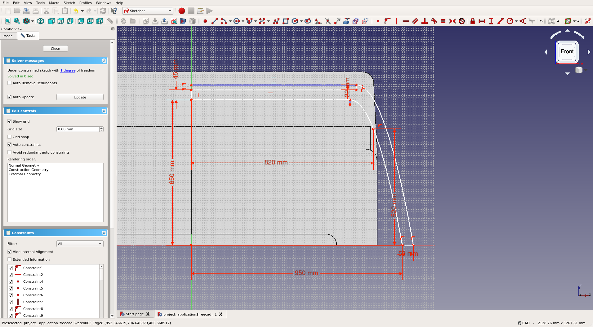
To fix this, I want to design a thin over-bed table that can be easily assembled and disassembled. I started by measuring and drawing the bed in FreeCAD in order to have a visual reference for dimensions, then half of one of the diagonal legs of the design I came up with:
I then rotated the sketch a bit, padded it, and used the MultiTransform tool to mirror the padded section on two planes: once to join the other half, and once on the non-rotated base-plane to create the second section that crosses the first. Next, I drew the tabletop.
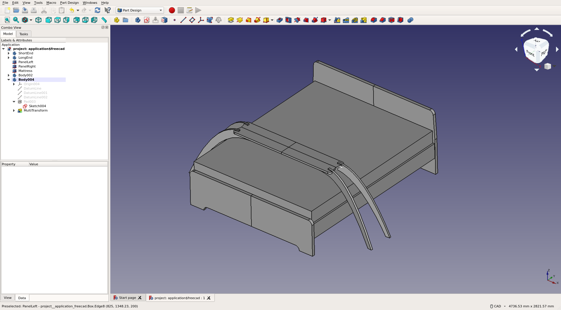
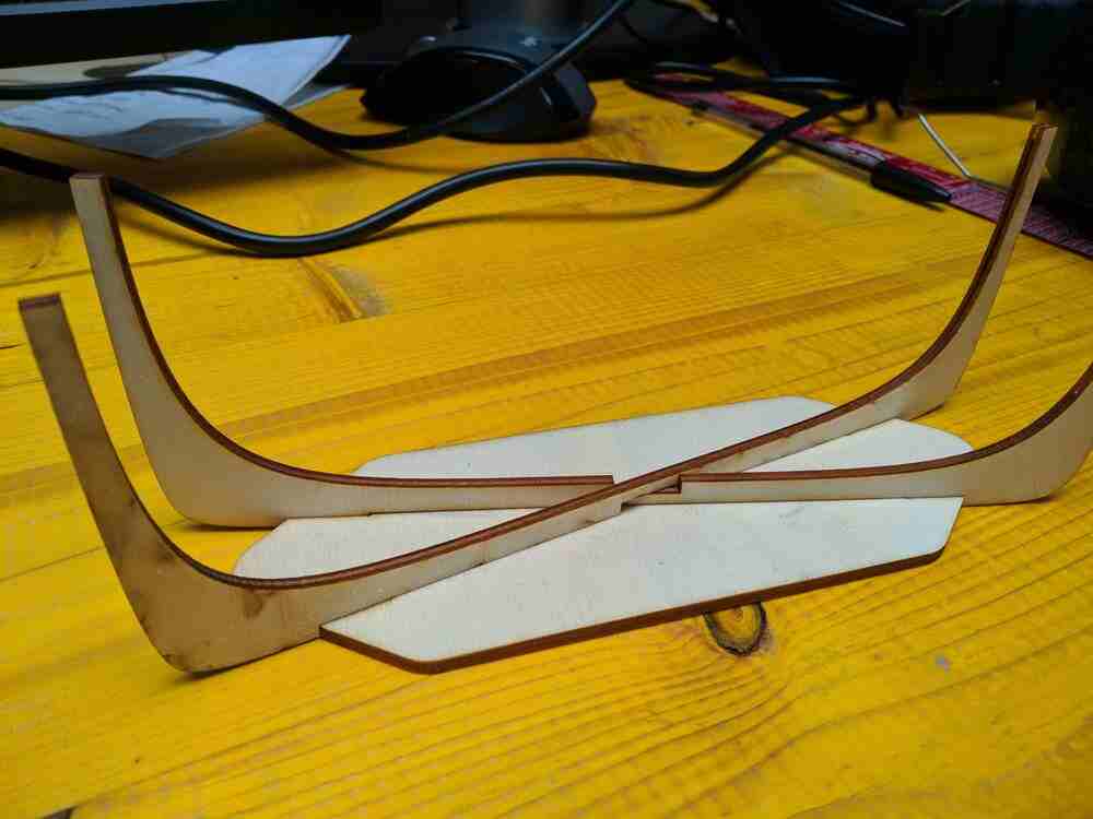
The tabletop is held in place via the four protruding edges of the legs, which match up with slots in the tabletop. The two independent support arcs cross at a lap joint, and are additionally supported by the table-top, which essentially locks them together.
Scale Model
To verify the design, I decided to lasercut a 1:10 scale model. I used the same workflow as for the drone propeller protector:
- First, create a 2D drawing using the FreeCAD TechDraw workbench
- Export the drawing as an SVG
- Clean it up in Inkscape
- Plot in Rhino
- Cut on the GLS lasercutter
Here is the 2D drawing:

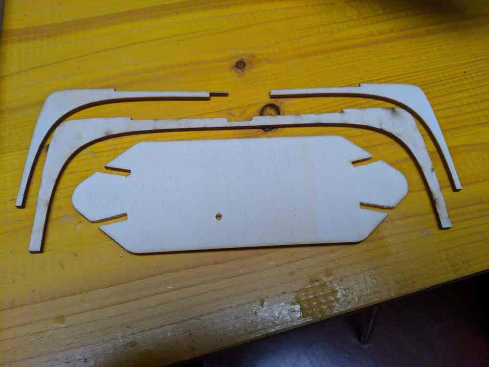
And the first cut attempt:
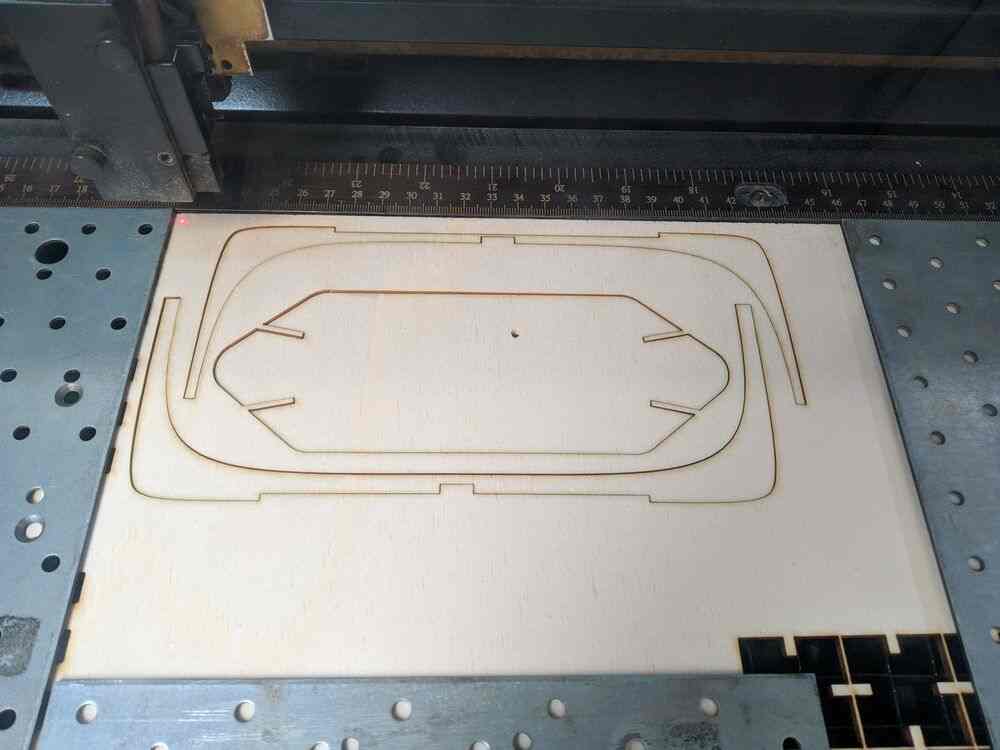
However on this first try I made two mistakes: Firstly, I scaled the model down to 1:10, but I didn’t think about the material thickness. The model was designed (parameterically) for 22mm plywood, so with the scale it would work with 2.2mm plywood, but I cut a 3.3mm sheet. I also offset the paths by 0.15mm in Rhino in order to counter the 0.3mm laser kerf, but it seems that for one of the two leg pieces I accidentally applied the offset in the wrong direction. As a result, the joints didn’t fit and the two legs were also of different widths. The leg with the wrong offset also became so thin in one part that it broke rather soon while handling it.
After realising the two mistakes, I went back into FreeCAD and changed my
material thickness to 30mm, to account for the 3.3mm stock, 0.3mm kerf and 0:10
scale: (3.3mm - 0.3mm) * 10 = 30mm. This time I didn’t apply any offsets in
Rhino, and ended up with a perfect press fit on the four slots, and clean lap
joint between the legs:
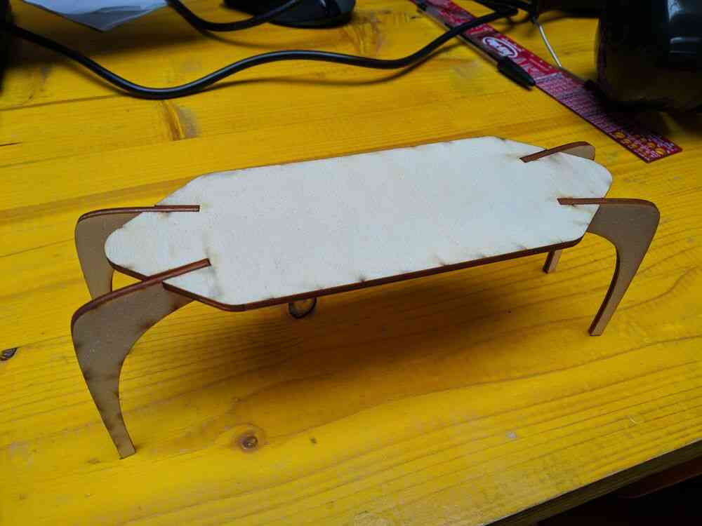
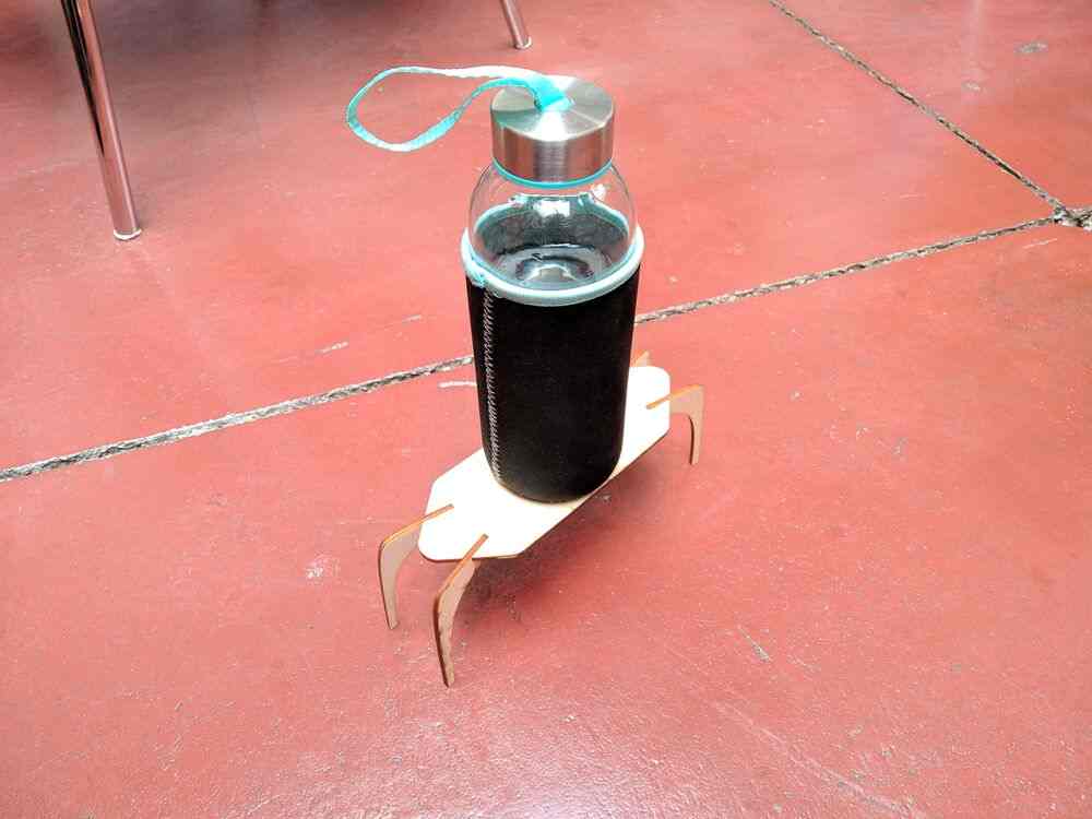
Despite the legs being very thin in the region of the lap joint, this model is quite sturdy. In this picture it is carrying about ~400g right over the weakest point:
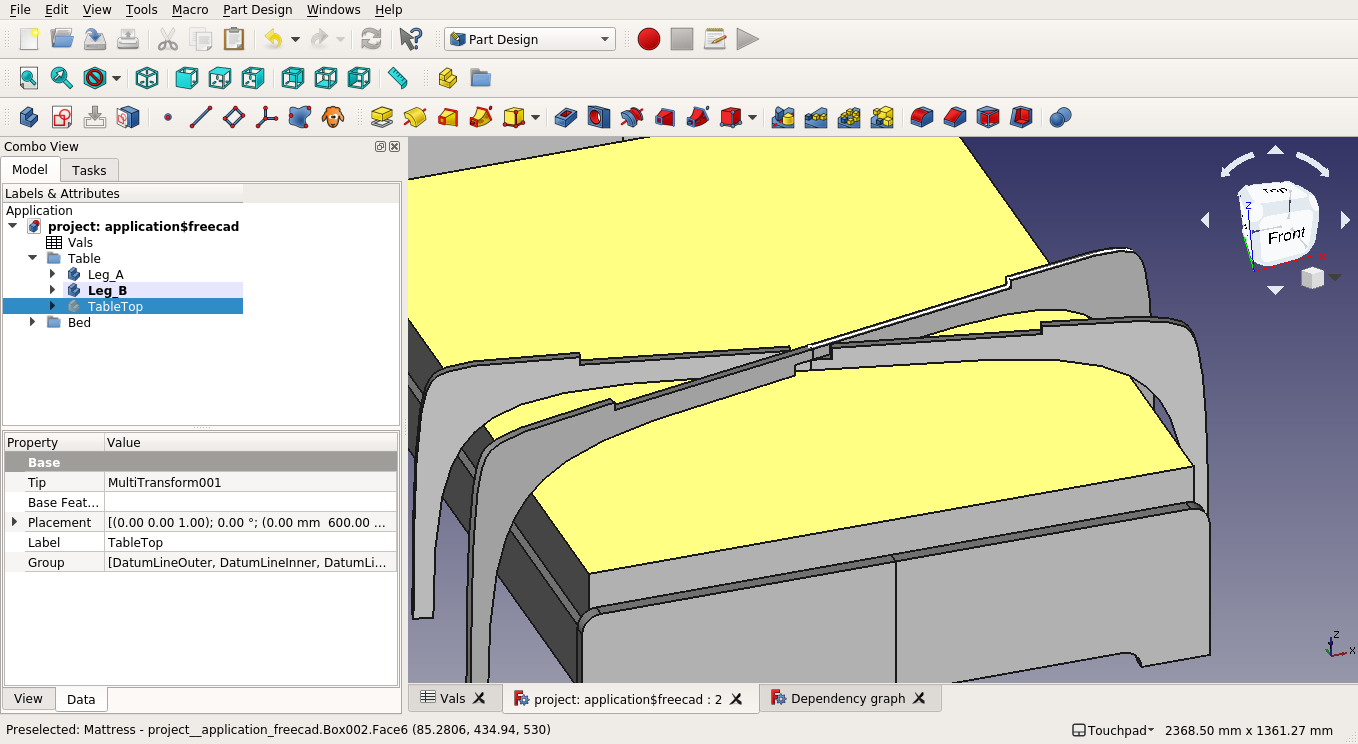
After some time checking the materials in the lab, and with the prospect of moving to a new appartement soon, in which the over-bed-table might be of questionable utility, I decided to downsize the design to a bedside table instead. I had to re-parameter-ize some of the design to make such a large change in scale work, since the splines for the curved legs are quite particular, but I think the design can now handle almost any format.
To make the parts fit together cleanly, I also had to add dogbones in the FreeCAD design prior to exporting the 2D drawing. Finally, I exported the design as a technical drawing again (this time at 1:5 scale):

CAM
Since this is a simple 2D design, I’m using VCarve to generate the toolpaths. It’s just a matter of importing the DXF vector file (same as the SVG technical drawing above), arranging it, and specifying positions for tabs to be placed. On the first try I couldn’t find the option of generating dogbones, so I added them in my design instead. Then once I was done with that, I figured out that they hid it in the “fillet” tool / submenu… In the end I went with the older dogbone-less design and added them in VCarve, as this keeps the workflow a bit more clean: the design does not depend on the tool used to cut, all of that knowledge is contained only in the CAM workflow.
machining
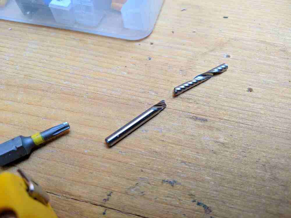
I machined the table on the ShopBot. My first CAM files were a little to aggressive on the feed rate, I finished one of the leg halves with no problems, but while milling out the tabletop I hit a harder piece of wood and broke my first endmill :(
I changed the speed in the post-processed file and removed the code that mills the first leg and tabletop to mill out the second leg at a slower speed. Then I re-prepared the tabletop at a 90° rotation to fir it into the remaining space on the stock and milled it at reduced speed as well.
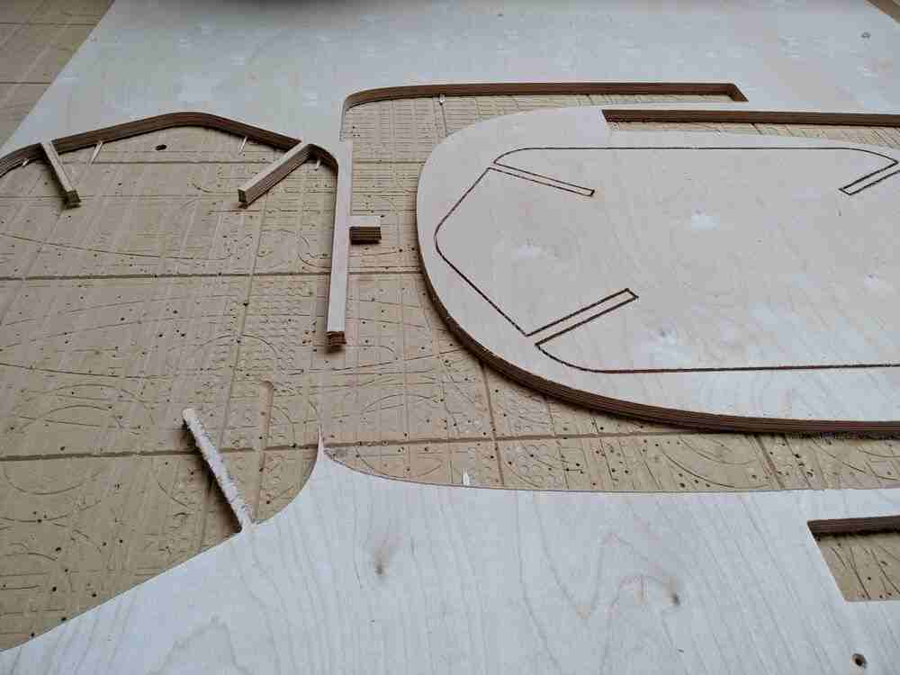
When removing the milled pieces from the stock, I didn’t take enough care holding the pieces in place while sawing through the tabs, and so some of the wood splintered quite far into my work. This was worst on the tabletop, but I can simply put that side on the bottom (and take more care next time…)
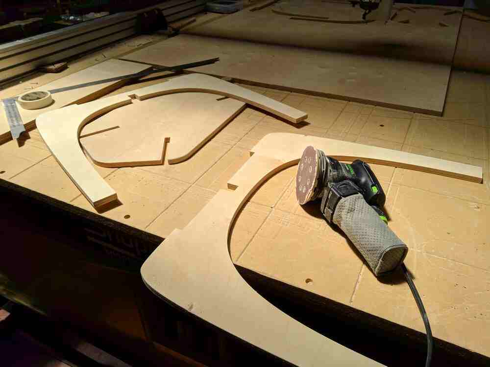
I then used an orbital sander to clean up all the cut surfaces and edges, most of which I chamfered slightly as well. After sanding, I applied a coat of some wood finish and let it dry overnight.
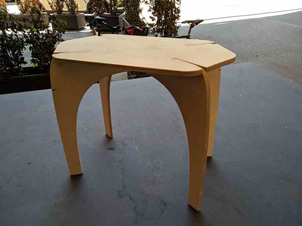
And here is the final result:
files
- FreeCAD design (FreeCAD 0.19)
- 1:10 SVG model drawing (mm units, see above)
- 1:5 SVG drawing (mm units, see above)