3d scanning and printing
modelling and digitization
In this week, I want to create a mockup for the ergonomic shape of the keyboard for my final project. I have tried some approaches for digital modeling in the past, including scanning the range of motion of my fingers, but I found that evaluating and using the data was extremely difficult. This week I want to try a more hands-on approach: physical modellng using modeling mass.
play-dough modelling
First I researched different recipes for making ‘DIY’ play-dough and modeling compounds. The recipes I found fell roughly into four categories based on their main ingredients:
- glue and paper mixtures
- cream-of-tartar mixtures
- starch and baking soda mixtures
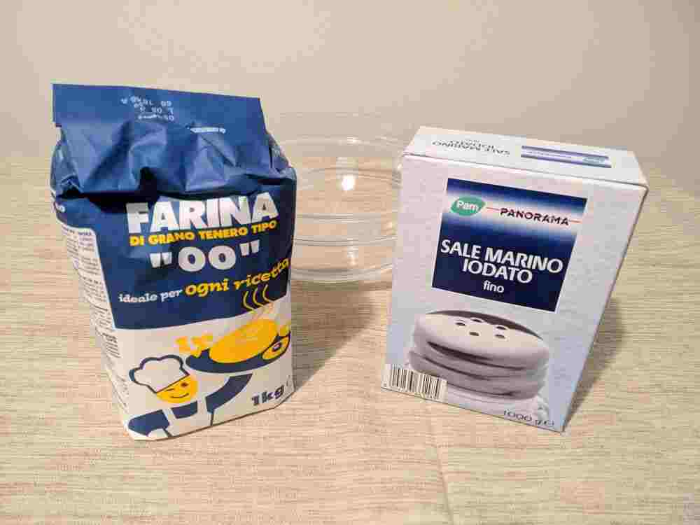
- flour and salt mixtures
I eliminated 1 because I expect it to be much messier and have a shorter working time, and 2 because cream of tartar is not as easy to procure as the other materials. The starch-based recipes are generally labelled as ‘air-dry’ play-dough, so I decided to go with a salt-dough recipe, which cures in the oven. This way I hope that I can work on the model as long as I want with a relatively stable modeling compound, before fixing it using heat treatment.
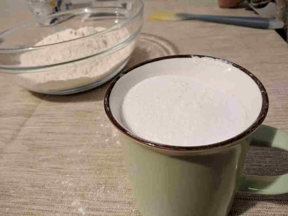
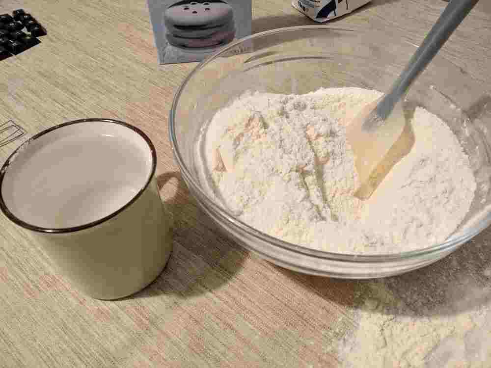
The recipe I settled on using was found on dishfunctinaldesigns.blogspot.com, and is essentially a 2:1:1 mix of respectively flour, salt and water. The ingredients are simply combined and kneaded. As with most dough, it is advisable to spread some flour on the work surface to prevent the dough from sticking excessively.
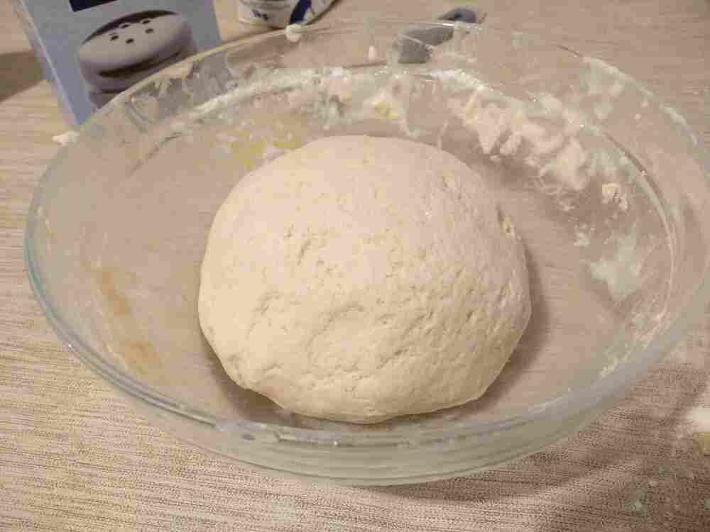
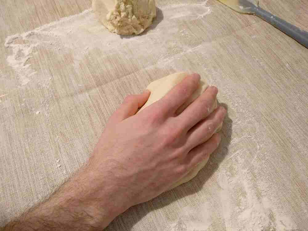
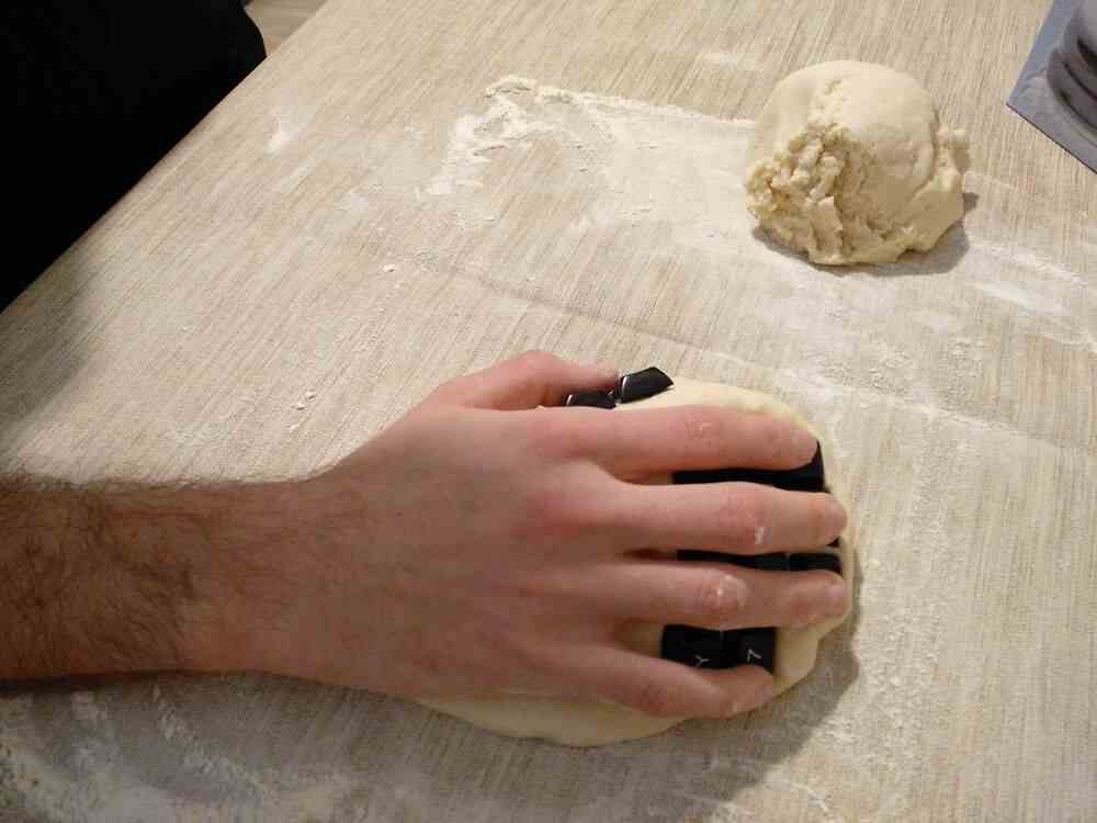
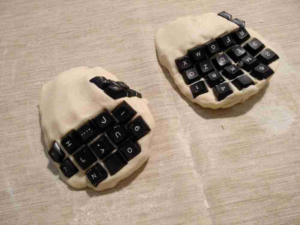
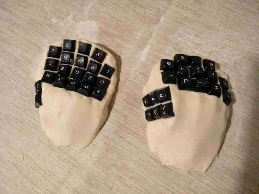
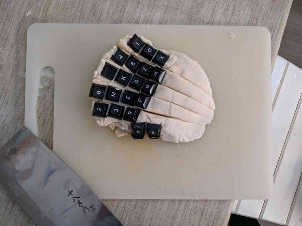
With the dough done, I took approximately half the mass and started to shape a comfortable resting shape for my right hand.
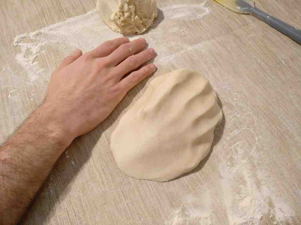
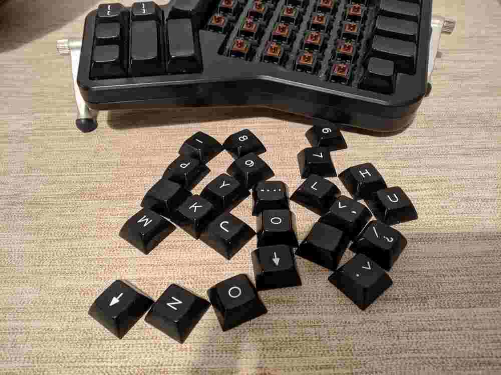
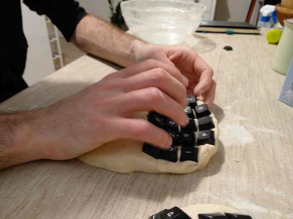
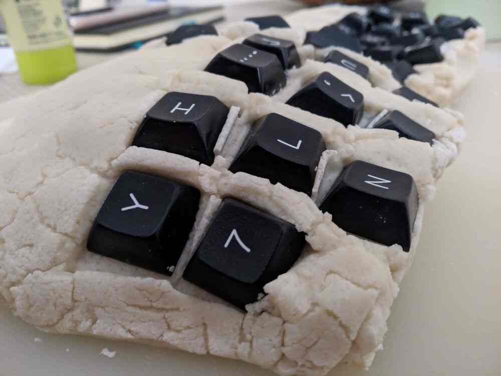
To test the key spacing and ease of access, I removed keycaps from my main keyboard, and started placing them on the model. This allowed me to get a reasonably realistic approximation of the feeling of using the keyboard, and let me experiment with different key placement positions and angles.
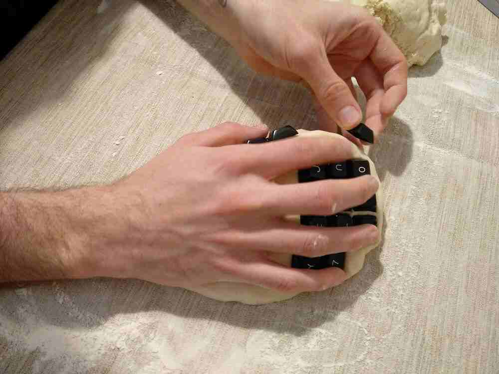
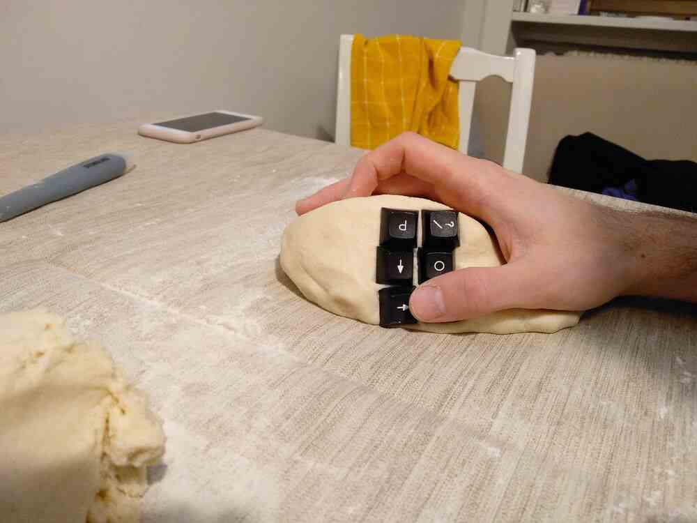
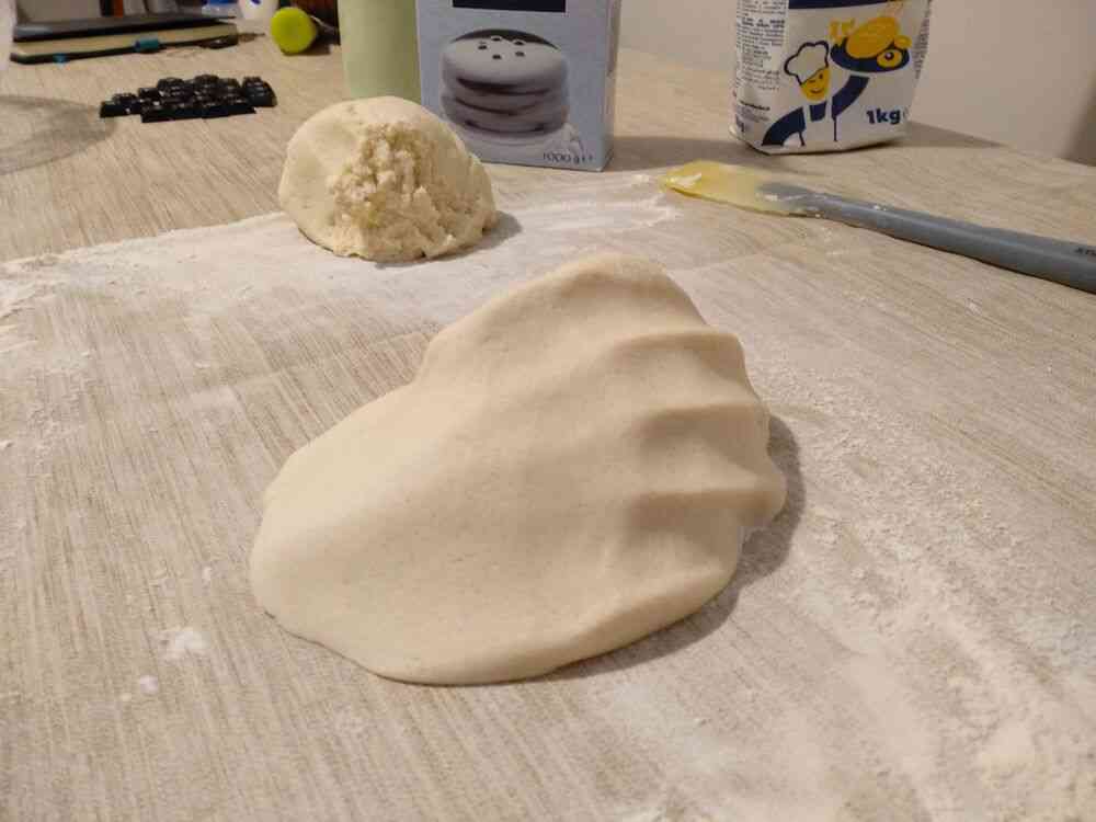
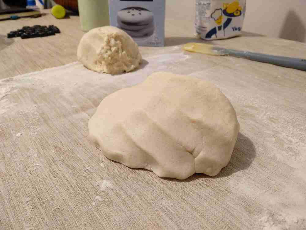
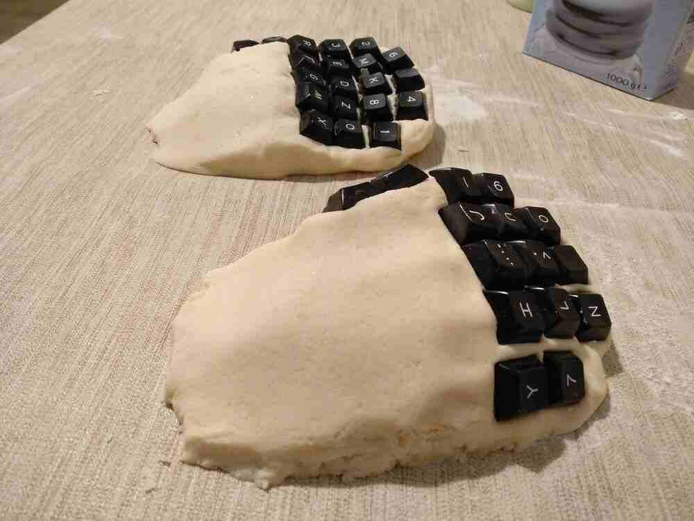
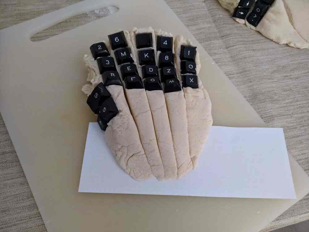
First I tried a convex shape for the main key array under the index, middle, ring and pinky fingers. Once I was happy with this design, I used the second half of the dough to create a different shape based on a concave “bowl” shape for the man key array, like the Dactyl Keyboard. Before trying it out, I found the shape somewhat counter-intuitive, but testing it with the dough let me understand the design better.
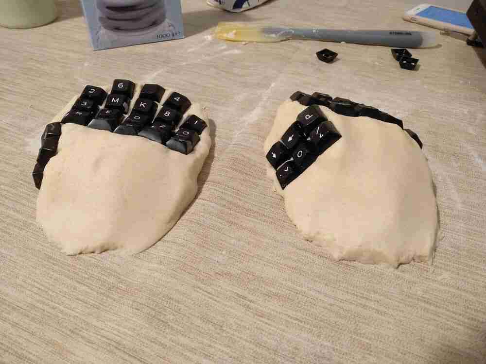
The first model I created is much more comfortable for the resting hand, because it supports the hand up to the knuckles and even a bit further. The “bowl” design has a bit less contact area, and has the fingers slightly curled and ‘loose’ in the air when resting, but this allows greater range of motion. Because of this, the first design only features three rows of keys, whereas the curved design features four.
digitization
To digitize the results, I am trying multiple different techniques. I experimented with a photogrammetry app for android, but only got a very low-poly model out that had too little resolution for my use case. The app (‘SCANN3D’) offered options for higher quality for paid service, but I did not try that out. Instead I took about 70 pictures each of the two models from a variety of angles (360° around the model from a flat angle, plus shots from different elevations) that I will try to use with some photogrammetry software on the PC later.
Because I wasn’t too sure how well that would work, I also tried an alternative approach. I cut the models into slices, and manually traced the section views onto pieces of paper using a pencil. I also marked specifically the positions of the keycaps. I created one such section view for the four main fingers on the “bowl” shaped model, and two views for the index and middle finger on the other one. In addition, I made a paper ‘map’ of the top view of the base of the “bowl” shaped model to capture the positions and angles of the section planes relative to each other.
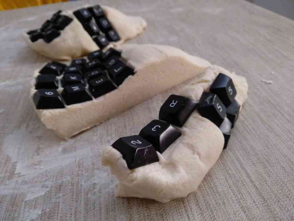
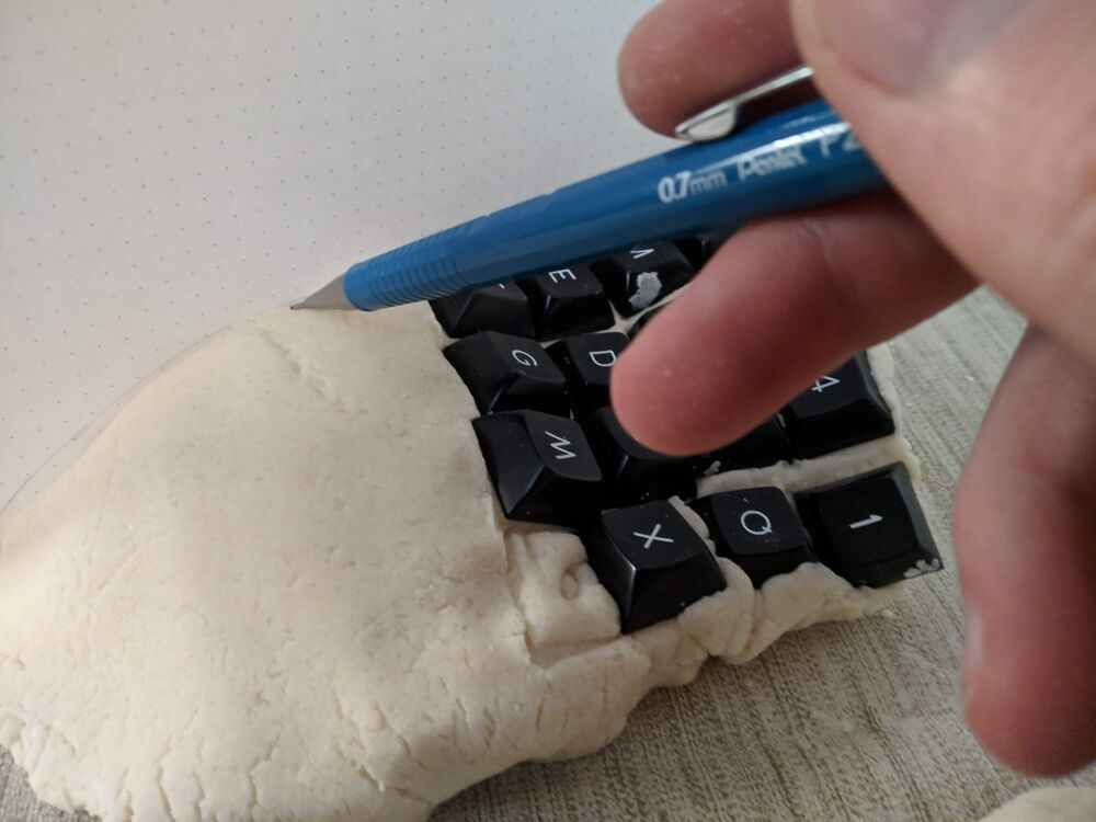
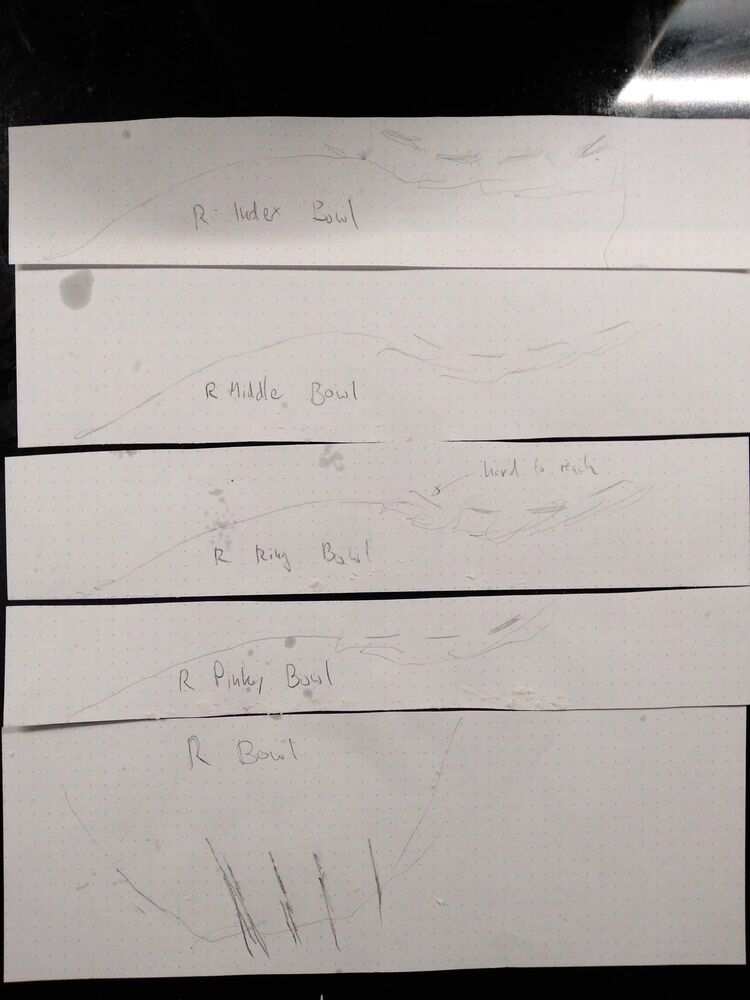
Between making a cut and tracing the lines, I had to carefully fix the model again, because even by slicing very slowly and using sawing motions the model generally deformed a little. In general, my dough was probably a bit too wet, as it tended to flow downwards with time and the keycaps also embedded themselves a bit too deep into the model from just the light pressure applied during testing.
After this, the models were in pretty bad shape and I decided not to try and cure them. Rather, I wanted to use a more powerful photogrammetry toolchain on a PC and see the different results. Looking at the options for Linux, I settled on Meshroom pretty quickly. It is open-source, configurable and extensible, the calculation processes can be paused and resumed, and there was a binary distribution for my system available.
I started by running the 64 pictures of my first model through it on my laptop (a Lenovo Ideapad Z580, with an Intel i3 and a Nvidia GT640M), and noticed pretty quickly that its computing power was not going to cut it for a full-quality process. It went through the feature detection and feature matching steps at decent speed (~10 minutes) and found solid-looking camera positions and features:
…but the DepthMap node was going to take about a day at least. I
stopped the processing at that point, and lowered most of the settings
on the DepthMap and DepthMapFilter nodes to about 30-40% of their original
values. This of course would have a drastic impact on quality, but I just wanted
to get a feeling for the output while I was waiting for my desktop PC to
arrive. With these lowered settings, the rest of the process took about an hour
to complete.
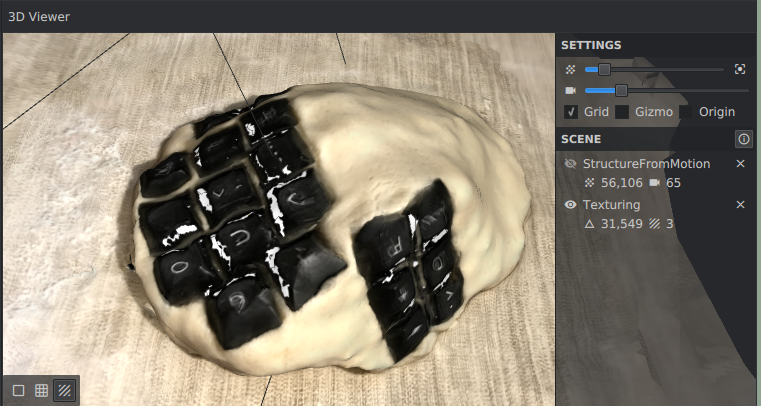
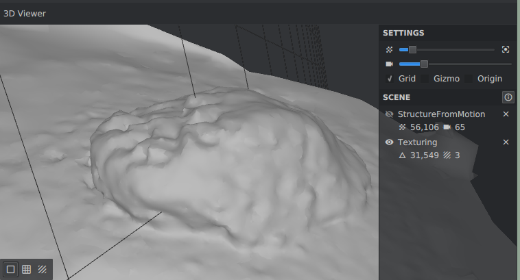
A few days later, I finally had my desktop PC set up (Intel i7, Nvidia GTX 1070). The same set of images at full default settings took 40 minutes to process now, and the results seem quite reasonable:
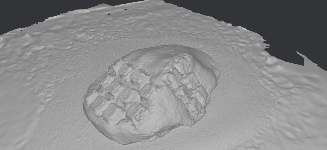
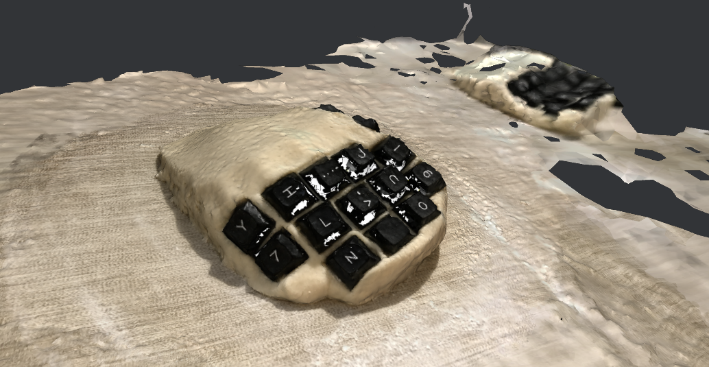
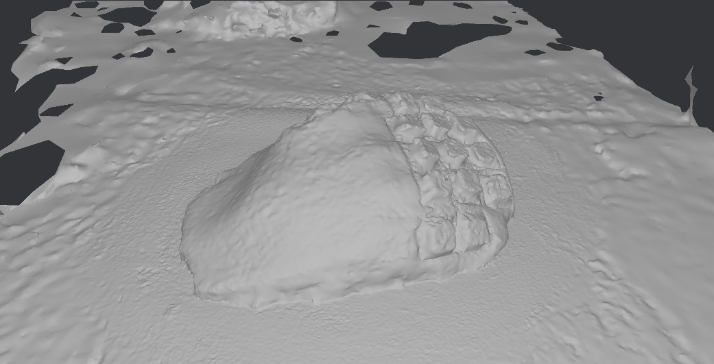
Here is the Mesh itself:
files
scan.glb(GLTF)
3d printing
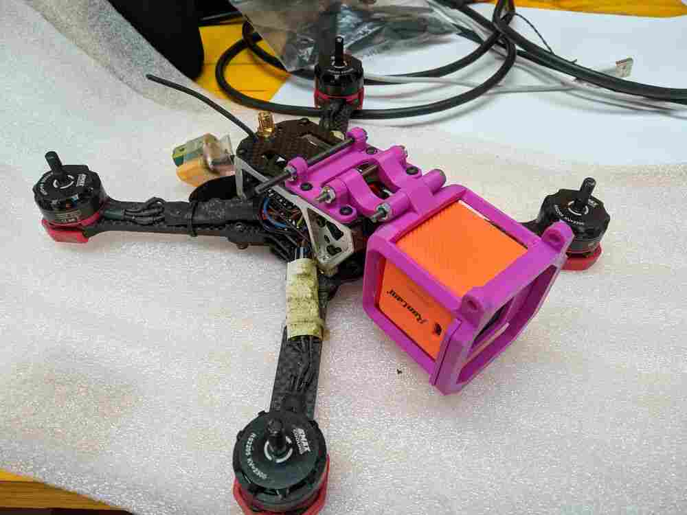
I recently bought a “Runcam 5 Orange” actioncamera in a small cube-shaped form-factor for recording HD footage from my FPV drone. To mount the camera on the top of the drone and at the correct angle, a mount is needed.
There are a number of designs on Thingiverse, but I couldn’t find one that satisfied all my criteria:
- fits the camera dimensions
- fits the pre-drilled hole pattern on my quad
- protects the camera from impacts from front and top
I did print one of the partial pre-made solutions, which comes in the shape of a wedge that fits my camera and quad but does not offer any protection:
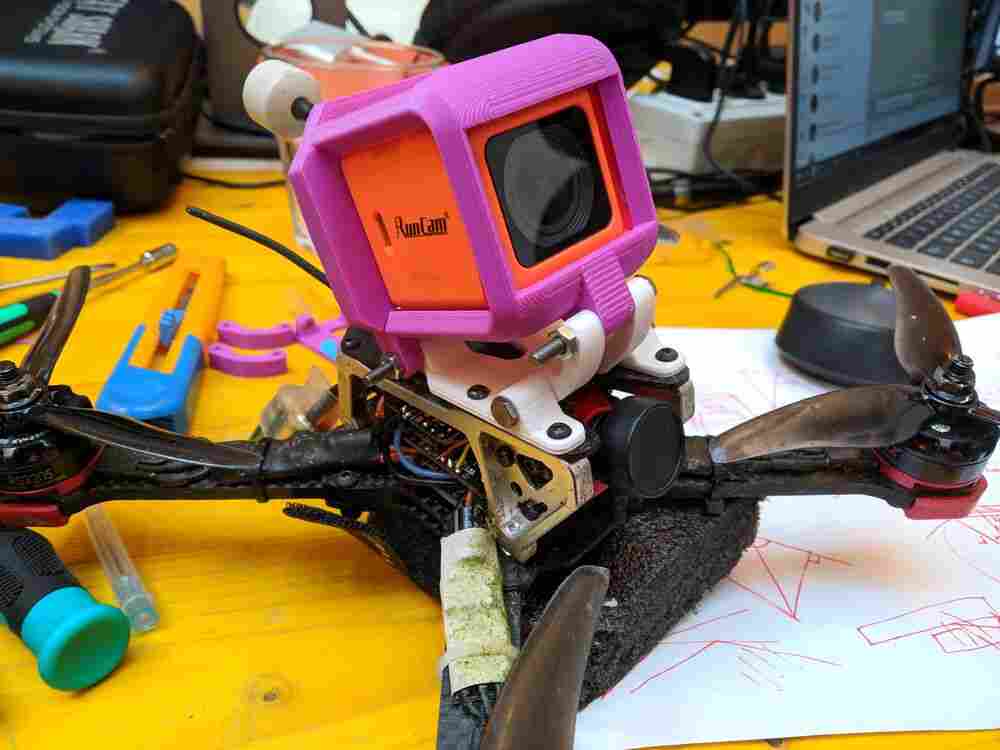
But then I decided to design my own solution. To save time, I found a premade model of the camera I bought on GrabCAD. Luckily, the original Fusion 360 design files are included, so I could use e.g. the chamfered edges directly as features to base my design on.
I designed a rigid case to encapsulate and protect the camera, with some thin foam added on some positions on the inside for impact dampening. The case hinges to the baseplate that is screwed onto the top of the drone on the back, and two “springs” connect the two in the front. This way the angle of the camera can be changed by simply replacing the springs with ones of different length. The final springs will be printed in TPU to be able to absorb the majority of the impact energy in a frontal collision.
After modelling everything, I exported the individual pieces into Ultimaker Cura, where I sliced them at a layer height of 0.2mm for our Wasp Delta 20x40 printer with a 0.4mm nozzle. I printed the case with supports and raft enabled, but disabled both for the other parts since they are all very flat and without major overhangs.
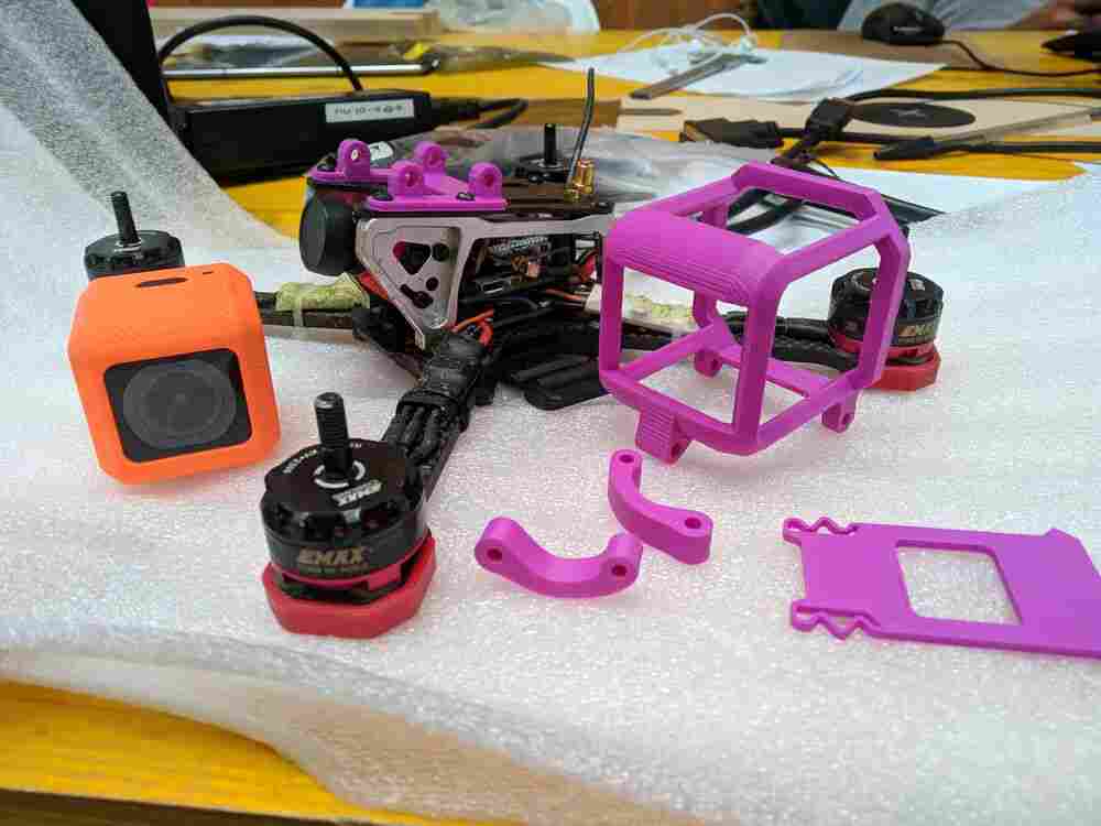
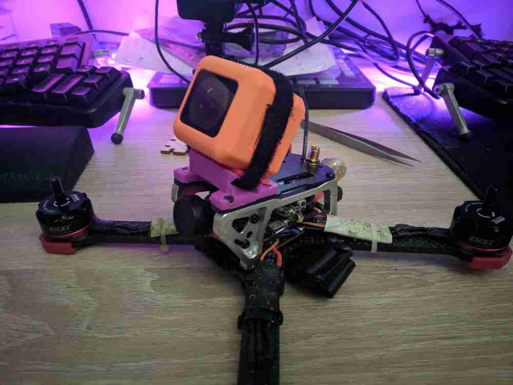
The parts came out pretty well and everything fit ok. The first baseplate I printed was a bit too weak though and broke quickly at the first minor drop. The holes for the bolts also had a little too much play, so on the next iteration I made them undersize and used a hand drill to open them up just enough for the right fit.
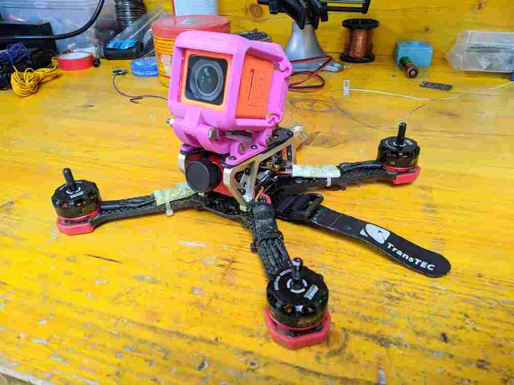
An added benefit of the hinged design is that by removing one of the screws, the whole assembly can be folded over to make the drone more flat for transport when the props and VTX antenna are also removed: