computer-aided design
libfive
i was pretty excited to try libfive studio, because I have some experience with parametric and procedural modelling in OpenSCAD, which has a roughly similar approach but is far more limited by design of its language, whereas libfive uses Guile Scheme to describe models. I also really like using an f-rep kernel because, while being hard to export and render, it is a very holistically accurate way of representing volumes. I also have some experience working with signed distance fields and raymarching (although in a purely visual context), so the concept was not too alien to me.
After installing libfive-studio-git from the ArchLinux AUR
and starting it up, I hit the first snag in the road: the rendered view
stayed empty when I added shapes, and even loading the tutorial didn’t render
anything. The interpreter was running though, since errors were being marked
correctly and logged in the console.
A quick github issue search revealed that this was a known bug that can be fixed by changing the Meshing Algorithm in the Debug menu (and changing it back):
With the basics out of the way, I set out to first model an individual keyswitch placeholder, since constructing my final project (a keyboard) consists essentially of placing these on an ergonomically-shaped plane and building a chassis around that.
I already know that I would like to use Kailh low-profile ‘Choc’ keyswitches,
so I looked for their datasheets, which I found in the keyboard.io
keyswitch-documentation repository:
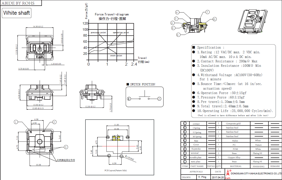
Not all the dimensions of the aesthetic elements on top are given, but I was able to make a rough approximation using three boxes:
(set-bounds! [-40 -40 -40] [80 80 80])
(set-quality! 8)
(set-resolution! 10)

(define* (box-centered-xy size #:optional (pos [0 0 0]))
    (let ((hw (/ (.x size) 2))
          (hd (/ (.y size) 2))
          (fh (.z size)))
      (box  (+ pos [(- hw) (- hd) 0])
            (+ pos [hw hd fh]))))

(define base_width 14.5)
(define base_depth 13.5)
(define switch_height 8.2)
(define t_height 2.65)
(define base_height (- switch_height t_height))

(define* (keyswitch #:optional (pos [0 0 0]))
  (let ((base (box-centered-xy [14.5 13.5 base_height]))
        (stamp (union (box-centered-xy [10 4 t_height] [0 0 base_height])
                      (box-centered-xy [3 4 t_height] [0 -1.2 base_height])))
        (hole (box-centered-xy [1.2 3 switch_height] [(/ 5.7 2) 0 0.1])))
    (symmetric-x (union base (difference stamp hole)))))

(array-xy (keyswitch) 2 1 [18 18])
It took a while to warm up to libfive in the end, mostly because while I know some basic Lisp I am not very familiar with Scheme, and the Guile documentation is not very friendly for quickly finding small pieces of information.
After designing the simple keyswitch, I played around with writing my own
distance functions for the shell for a while, but found it pretty difficult
to think mathematically about such a complex shape. I managed to get a rough
curvature using some power functions, then pushed it around using the repel
function to get the rough shape that I need:
(set-bounds! [-120 -120 -120] [120 120 120])
(set-quality! 8)
(set-resolution! 10)

; clojure-style 'thread-first' macro
; taken from https://stackoverflow.com/questions/57864202
(define-syntax ->
  (syntax-rules ()
    ((_ a) a)
    ((_ a (b c ...)) (b a c ...))
    ((_ a b) (b a))
    ((_ a b c) (-> (-> a b) c))
    ((_ a b ... c) (-> (-> a b ...) c))))

; shorthand for exp+scale
(define (pow-scale x s e)
  (expt (* x s) e))

; the main curve shape,
; built from three power functions (one x, two y)
(define-shape (curve x y z)
  (+ z
    -20
    (pow-scale x .05 4)
    (pow-scale y .07 2)
    (* (pow-scale (+ y 40) .11 4) .002)))

; the repel-points
(define r1 [-30 -30 20])
(define r2 [-100 -50 0])
(define r3 [-40 40 0])

; previewing of the repel-points
; (change to #t/#f to show/hide
(if #f
  (union
    (sphere 30 r1)
    (sphere 30 r2)
    (sphere 20 r3)
    (sphere 0) ; dummy for commenting out the others
  ))

; push the surface around with 'repel' a bit,
; then add a straight base extrusion
(let* ((hull (-> curve
        (repel r1 30 1.2)
        (repel r2 30 3)
        (repel r3 20 1)
        )))
  (union
    (intersection hull (half-space [0 0 -1]))
    (extrude-z (remap-shape hull (x y z) x y 0) -10 0)))
In this clip you can see the raw power-function-curve, and then how the three
repel-spheres come together to form the shape.
I am actually pretty happy with how that looks, but the process is too indirect for working with this result: to create an ergonomic shape I need to have very direct and fine control over individual features in order to iterate on the shape. The sculpting features in libfive are great, but don’t really lend themselves to this approach I think.
Another reason that I probably won’t be using libfive for many projects is that it runs prohibitively slowly on my current laptop, to the point where other applications (like the browser) slow down to the limit of usability.
files
freecad
I tried FreeCAD because I would much prefer having a fully open-source
workflow (working on Linux, there actually aren’t too many alternatives
anyhow). To start off I installed freecad from the AUR,
which took forever to build (2-3h on my laptop). After building a dependency
versioning error that caused multiple workbenches not to work (selecting
them would cause a popup with an error message concering libimage). One of
the affected workbenches was the TechDraw workbench for creating technical
drawings as documentation, which I wanted to try, so I tried the alternative
freecad-appimage AUR package, which is distributed as a
feature-complete binary. Here all workbenches worked out of the box.
Once again, I began by modelling the Kailh keyswitch:
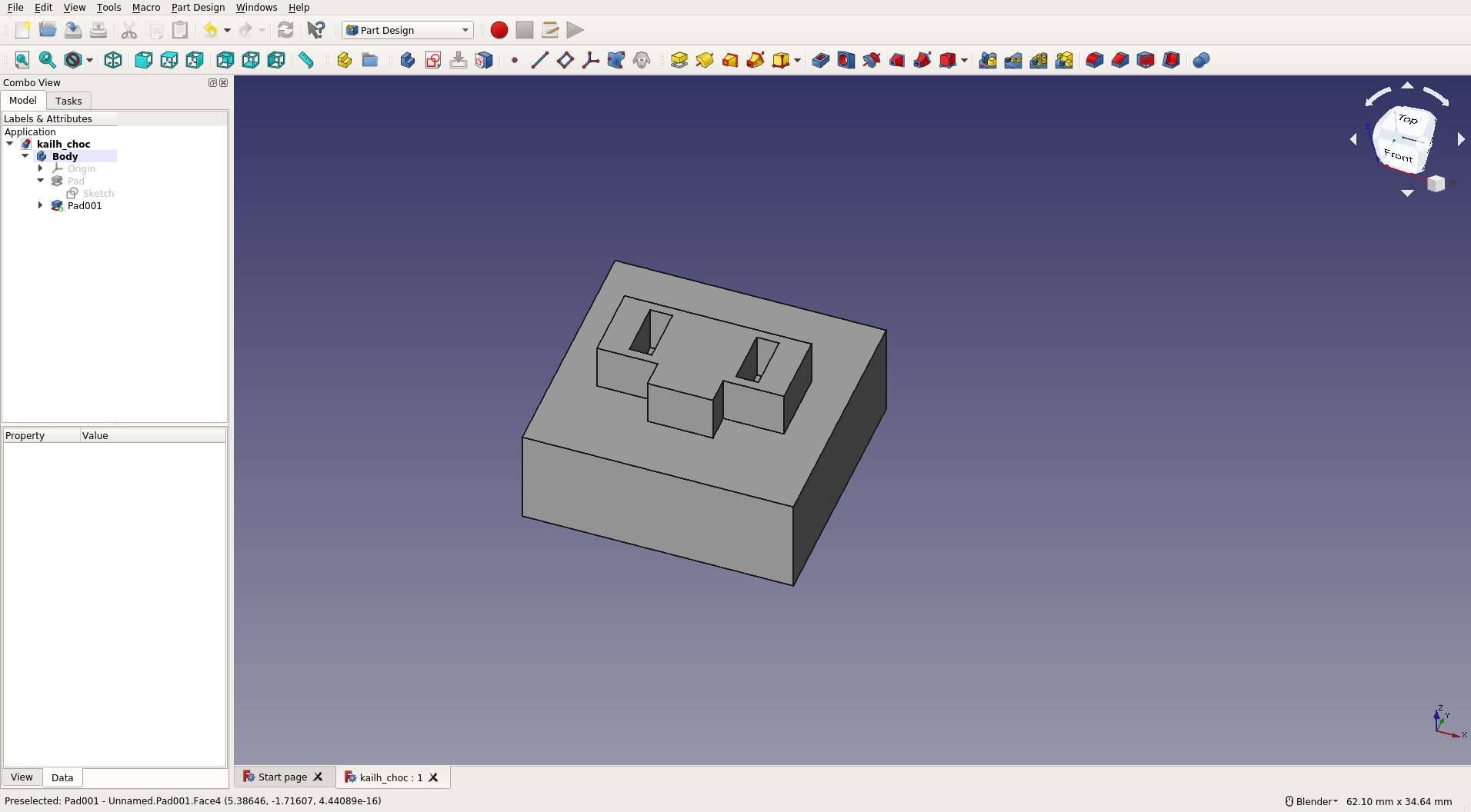
I did this by first creating a sketch with a simple rectangle on the XY-plane (top) and using the ‘pad’ operation to create a box from that. Then I added another sketch on the surface and drew the T-shaped feature and holes, which I extruded with another ‘pad’ operation. This part was easy enough and very similar to Autodesk Inventor, which I had a little bit of prior experience with.
Next I decided to try the Loft feature in order to create the curved keyboard hull. First I drew a sketch on XY-plane and created an irregular prism shape as a base to attach further sketches to. I used the Cross Sections tool from the Part workbench to create two sections through the block, and drew curved sections as sketches. Then I sketched rectangles on the front and back of the prism and created a Loft operation through the profiles. Here is the result:
First of all, I should note that I experienced three crashes while working on the loft operation. That put me in the habit of saving very often, which thankfully happens instantly. However after about an hour and a half of fiddling with the profiles, I still don’t have a shape even close to what I wanted originally. Maybe Lofting is just not the right process for this kind of shape.
I’m going to move on to the next tool at this point because this has taken up quite an amount of time. While the keyboard hull definitely was not a success, I am finding FreeCAD okay to work in in general, and I’m expecting it to do pretty well for the majority of projects that I see myself working on (most of which will have much simpler shapes).