
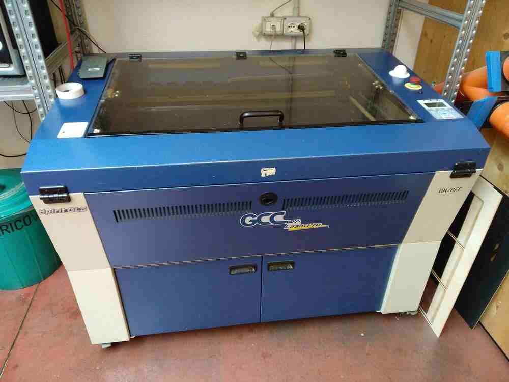
The laser cutter at OpenDot is a GCC SpiritGLS CO2 laser cutter. It has a work area of 960x610mm and can comfortably cut acrylic and plywood of up to about 12mm strengths.
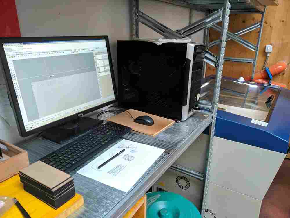
The Lasercutter is connected via USB to a dedicated CAM PC installed here at the fablab. The CAM PC runs Rhino 7 on Windows, which is configured to open a template file with the laser cutters work area on a locked layer. I had never used Rhino before, but with Antonio’s instructions it wasn’t too hard to get started. The workflow for cutting a file is something like this:
Import command to import a DXF file from a USB keyJoin commandPrint Color is set to By LayerHatch command to do thatproperties windowPower at 100% and adjust only the speedPower and PPI settings as welladvanced page set the position mode to relative
window selector. This can be useful to align file contents with the laser.print sends the document over to the printerTo characterize the kerf of the laser and experiment with different settings, we used a ‘kerf test generator’ Sol wrote using SVG.js. You can try the generator directly in the browser on his personal documentation.
We measured the plywood that we were going to cut with calipers, which came to a thickness of 2.9mm. We then used the generator to generate a test pattern with corresponding cutouts and a kerf scale from 0.25 to 0.35mm. We measured a kerf of 0.3mm and found that under-adjusting slots for a kerf of 0.25mm gave a good tight fit for press-fit joints.
We then ran a series of tests in order to characterize the speed and power settings in relation to each other. We used the lab-provided guideline of 6% speed and 100% power at 500 PPI as a starting point, and made a matrix of test cuts adjusting relative to this initial value. The columns have a relative speeds of 80%, 90%, 100%, 110%, and 120% (left to right) wrt. the 6% guideline, whereas the columns have a power setting of 100%, 90% and 80% (top to bottom). Towards the low-power and high-speed corner of the matrix the laser started to struggle with cutting through the whole material, so that the final piece in the 3rd column was already not able to be removed from the surrounding material easily anymore.
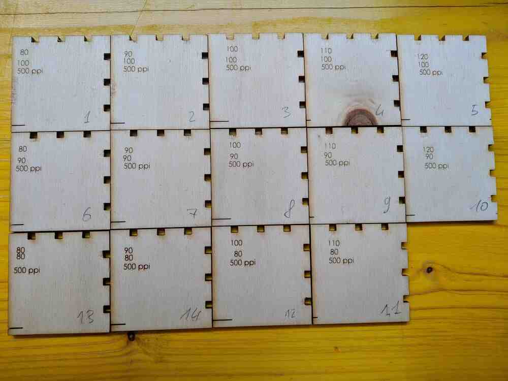
We cut the Matrix row by row with the same setup in Rhino: At the beginning we placed the five cuts, one per column, on five layers and gave them five different colors. Then we labelled them on a separate layer for engraving and set up the different pen settings:
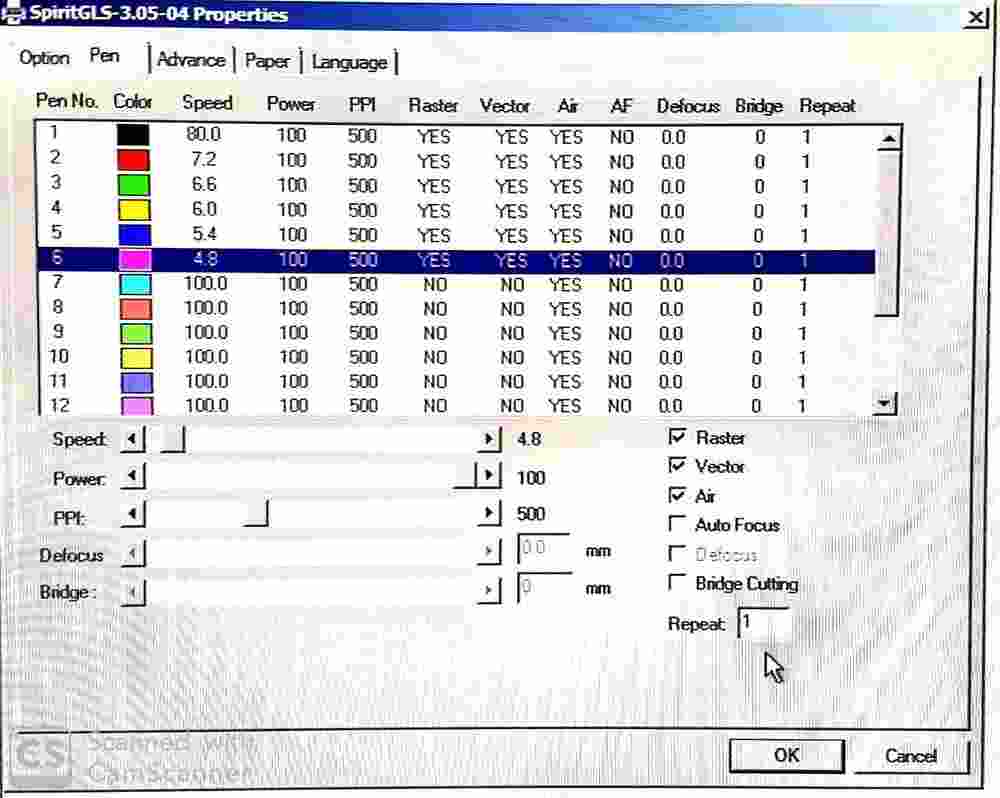
To print a column it was now enough to quickly adjust the power of all layers, manually move the cut head down one column and do another series of cuts.
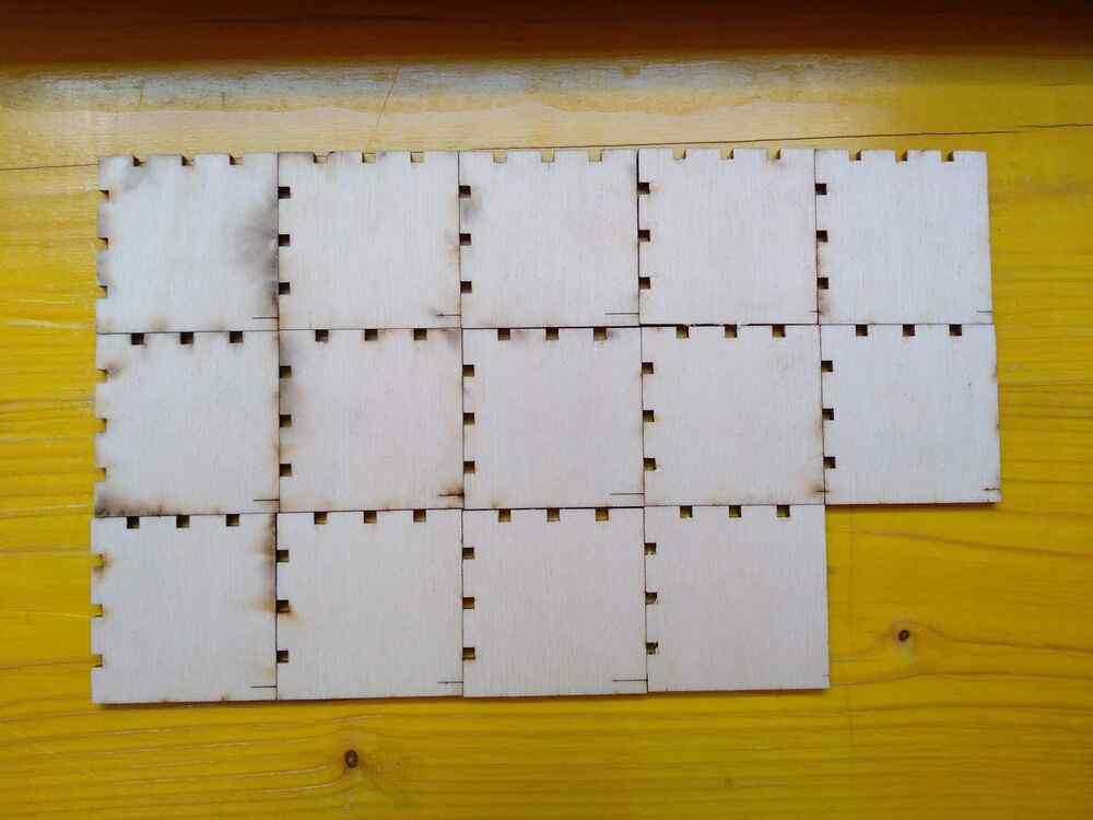
On the back of the tiles (pictured here in the same arrangement as the fronts above), it is clearly visible how excessive power and lack of speed cause charring on the edges of the cuts.
Based on these results we concluded that cutting at 6% speed and 80% power gave the best results out of the settings we tested, but noted that 120% speed and 100% power provided similar results while using the laser’s maximum output power, using the time a bit more efficiently.