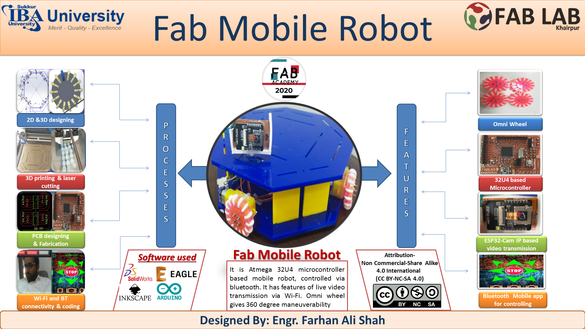
Summary Slide of Final Project
Final Demo
Initial Idea
My initial idea for final project was to make low cost mobile robot having 3 DOF robotic arms. Robot will have Omni wheels so it can move in any direction. It will have camera at front which can rotate around and send the video to the user. 3DOF (degree of freedom) robotic arm will be placed on top of mobile robot. It will have suction cup as end factor, connected with pump and pneumatic value to control its suction (when to create suction and when to leave). These all will be controlled by using mobile app via Bluetooth.. I got this inspiration from "KUKA Robotics". For futher details you may visit here.
Prof. Neil's Comments
During my review, Prof. Neil said that my idea comprise of 3 project. 1. Mobile Robot 2. Robotic arm 3. Suction mechanism. Further he said that I need to do only one for Fab academy, rest 2 I can do for myself in future.
Modified Idea
After Professor’s comment, I decided to make Fab Mobile robot having omni wheels and controlled via Bluetooth. It also have ESP32-cam based camera which transmit live video via Wi-Fi. Everything in this project is indigenously designed and fabricated during Fab academy 2020. My project plan was to design and fabricate part of Final project in my weekly assignment. Final assembling and code will be done in last. My strategy work very well. Almost 90% components are designed and fabricated in weekly assignment and used in final project. In this page, I will show making of each part used in the final project along with the link of that week in which that part was made.
2D and 3D desiging of omni wheel
Omni wheel which I designed is made of two parts, main big wheel which is laser cut and other is small wheel which is 3D printed on flexible material.
Big Wheel
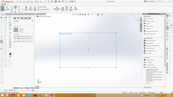
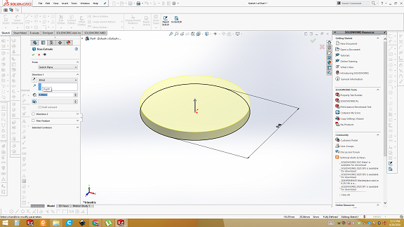
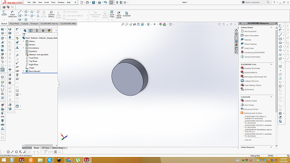
So first of all open the solid works and select the plan. Draw a circle of diameter of 45mm and apply the extrude boss command.
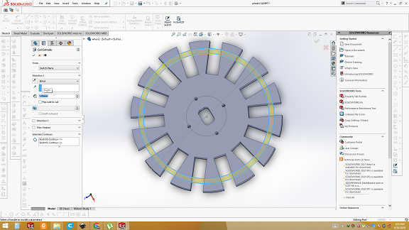
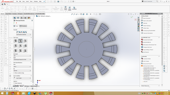
Select the face of circle and draw the rectangular slits in which small wheel are fitted. Select the circular pattern and draw the 14 more with equal distance. 14 small wheels will be inserted here. Then draw the hole for nuts and motors.
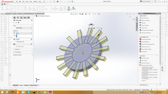
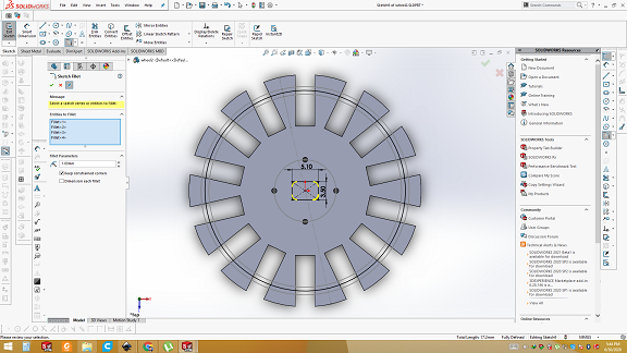
Draw a two line through center of rectangular slit for metal rode in which small wheel will be put in. Diameter of rode is 1mm so distance between two lines of 1mm and extrude cut is also 1mm
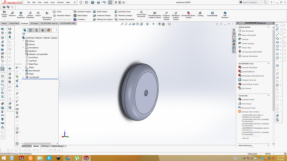
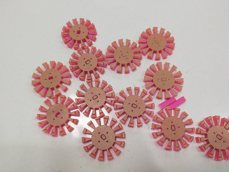
Small Wheel
Now it is time to make the small wheel which can be fitted into slot of big wheel. Draw a circle and extrude it. Size of extrude should be less than the width of the slot so it may not have any friction. Use the Flit command on the edges to make it smooth.
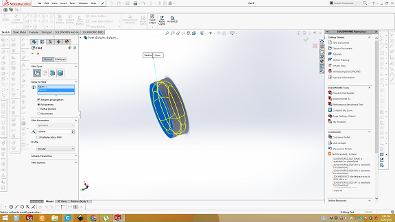
Here is final result of small wheel. Save as .stl and it is ready for 3D printing.
Open Assembly in Solid works
Open the assembly in solid works and bring two big wheels. Align them using "Mate" command. Then export the small wheel and align in the slot. Select the small wheel and select the circular pattern and increase the number to 14 with 360degree angle. Here is the final Omni wheel designed by me.
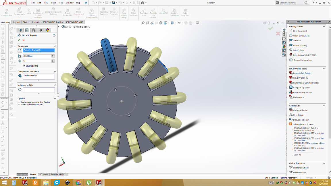
NOTE: Hole of motor is not shown in the assembly because first I verified in assemble then made a hole in big wheel for motor.
Assembly of Omni wheel
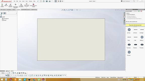
Make drawing from sketch
After verifying in assembly I made drawing on a big wheel’s part. A new window will appear and take the front side of the drawing and put on the main plan. Save as .DXF fie. I want to laser cut this part so I need pdf in 2D form. Now open .DXF file in Inkscape.
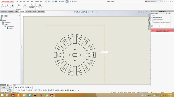
Open in Inkscape
Open in inkscape and fill the marked area with black color. I need to make slot using engraving. In the slot metal rode will be put between two big wheels which hold the small wheels. Convert outer boundary with stroke size of 0.001inch for cut.
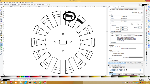
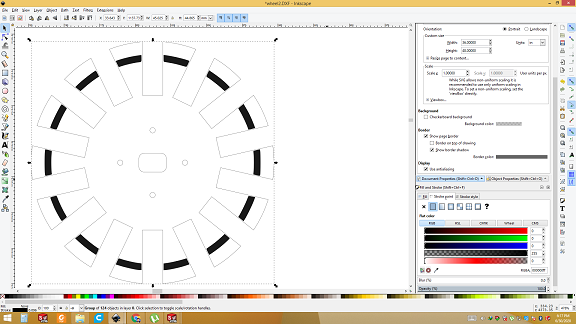
Now save as .pdf and it is ready for laser cutting.
3D Printing of Small wheel
.stl file is opened in Cura and set the layer height. Then save gcode. Gcode is then given to 3D printer.
Final result of small wheel
laser cutting of big wheel
After pdf is generated, it is sent to epiloger. Give the thickness of sheet and place the sheet. Then start laser cutting.
Final result of Laser cutting
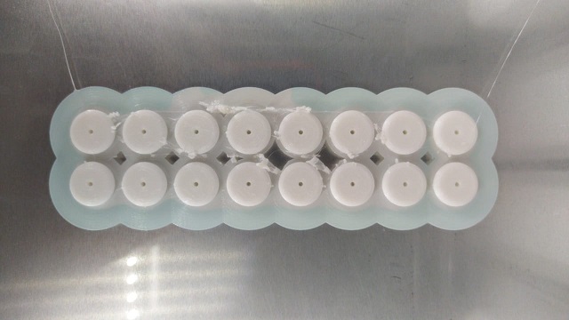
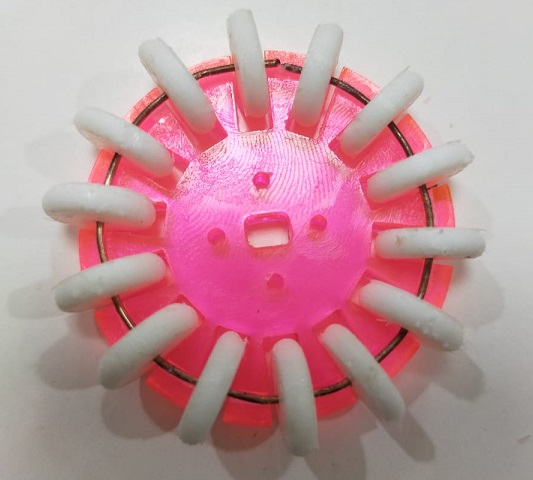
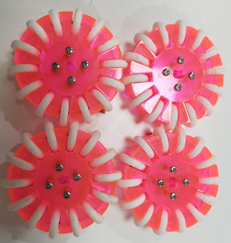
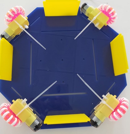
Assemble the Omni wheel
Take one big wheel and hard metal wire which is bendable. Bend the wire so it can fit inside the slot of omni wheel. Then put wire into 14 small wheels. Place the small ones into the slot as shown in the picture. Now take one other big wheel and place on top that. Use screws to tight the wheel. Here is finally Omni wheel is built.
Base of Robot
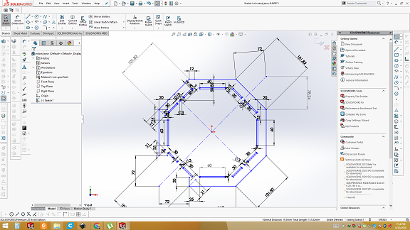
Most important part of our Fab mobile robot is Base, on which electronics, camera and omni wheels are placed. First of all open solid works. I want to make hexagonal shape. Hexagonal shape has 6 sides so I can place motors and wheels in both "X" shape as well in "+" shape.
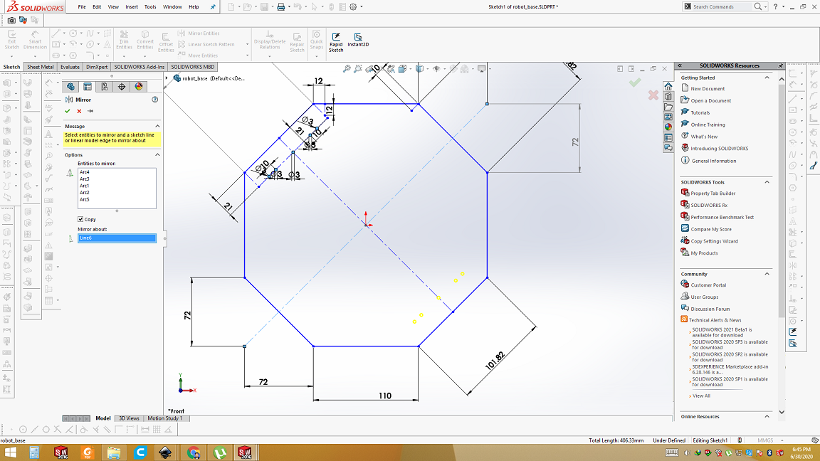
Making holes and slots for motor and slits
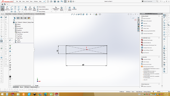
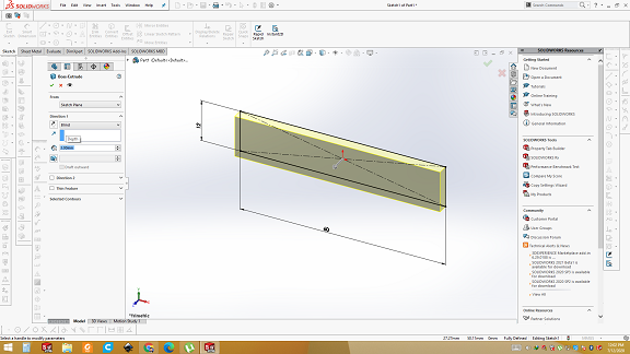
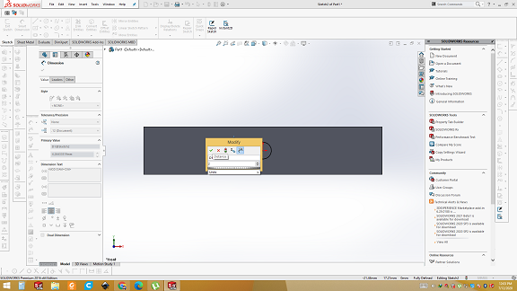
There are two parts of base. One is bottom part and other is top part. Both are connected through slits. Slits will be press fitted into holes. So first I measured the thickness of the acrylic sheet and then make a hole for slit. After that I extruded it to visualize in 3D.
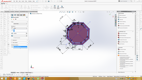
3D view of Base of Robot
Bottom and top part of base are identical. Only difference is that the top has slot for servo motor.
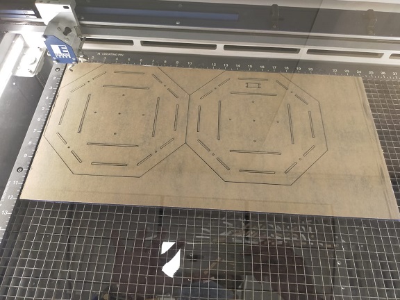
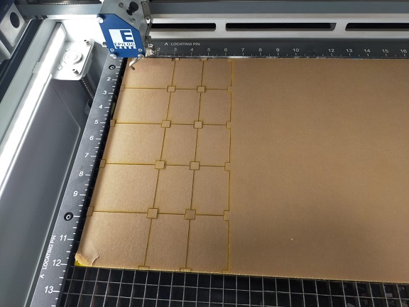
laser cutting of Base of Robot
After designing, file is sent to Epilog manager and laser cutting process is done.
Final Result of Lasercutting of Base and slits
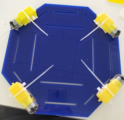
Assembly of base
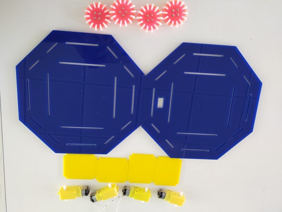
Take all the components. First of all I have to fix the motors, then solder the wires to the motors and then put wheels into the motors.
Electronics
Now it is time to put electronics into the robot. Four electronics board (PCB) is being fixed into the bottom part and one is fixed on the top part along with servo motor. Main and the most important part of electronics is Atmega 32U4 based microcontroller break out board. It works as the brain of this robot. Second board is two L293D motor driver breakout board. This board helps the microcontroller to drive the motors through external supply. Third board is the board for HC-05 Bluetooth module which is connected with Atmega 32U4 board through jumper wires. This is responsible to form the link between mobile BT app and microcontroller. Instruction sent from mobile app is received through HC-05 module then transferred to microcontroller for further decision making. Fourth one is power supply breakout board. It contains voltage regulator. 2S LiPo battery which we are using, it gives us around 7.5-8v but our microcontroller, servo motor and Esp32-cam works on 5v. So this breakout board is supplying desired voltage. Final part is ESP32-cam PCB board in which ESP32-cam will be mounted and that board is mounted on servo motor on the top part using 3D printed holder.
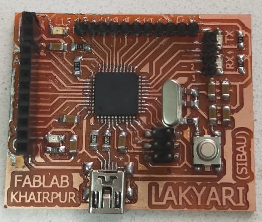
Atmega 32U4 breakout board
This is the brain of my Fab Robot. It has 13 digital input/output and 6 analog input/output which also can be used as digital input/output. I have designed this board in embedded programming week. Details of designing and fabrication of this board along with testing can be found here.
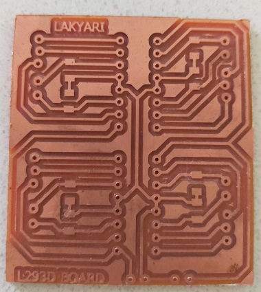
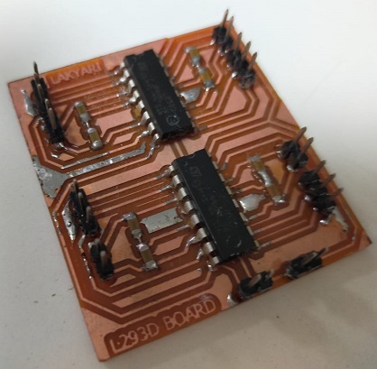
Motor Driver Board
I have designed this motor driver board in Output week. I have two L293D motor driver ic, which can drive 4 motors at a time (1 L293D IC drives 2 motors). It needs external power supply at which motor will run and three control signals for each motor from microcontroller i.e. one is enable, signal 1 and signal 2. Making enable high through microcontroller will allow drive the motor. Signal 1 signal 2 is used to control the direction of the motor. If signal 1 is HIGH and signal 2 is LOW, motor will run in forward direction. If signal 1 is LOW and signal 2 is high motor will run is backward direction. Making both signals 1 and 2 LOW will stop the motor. Making both signal HIGH produce invalid condition. I have designed this breakout board to control 4 motors as in my Fab Robot have 4 motors. Details of designing, fabrication and testing of this board can be found here.
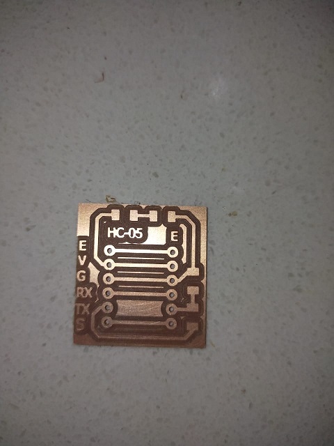
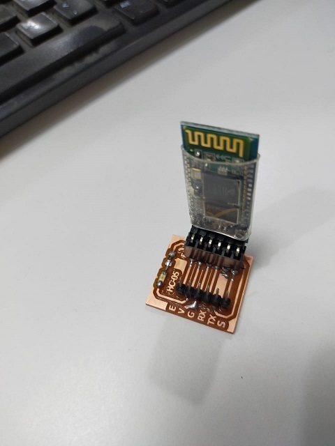
HC-05 board
HC-05 module is Bluetooth module. This board contains voltage divider circuit as RX pin of the HC-05 is 3.3v tolerant. This is responsible for communication between mobile app and the microcontroller. I have made this board in Networking and communication week. Further details regarding designing, fabrication and testing are available here.
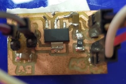
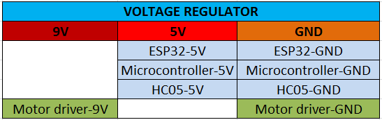
Voltage regulator
I have made this voltage regulator based on 1117 ic which gives 5v. It also gives 9v directly from battery to motors as well.
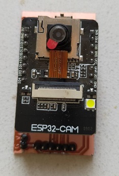
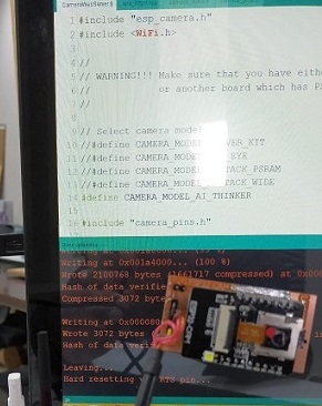
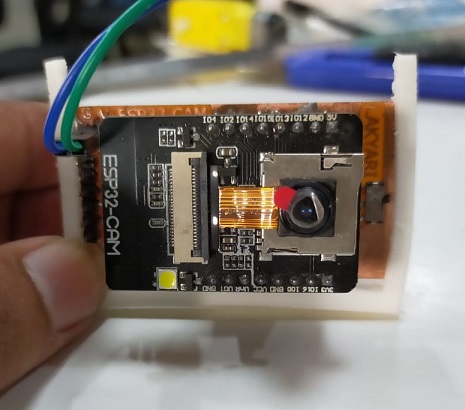
Esp32-cam board
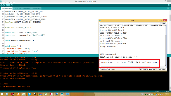
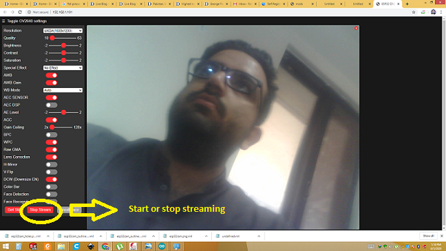
The last but important electronics part is Esp32-cam board. Esp32-cam is used for wireless live video transmission via Wi-Fi. Esp32-cam is programmable via FTDI cable. GPIO-0 pin need to connect with ground while programming, once code is uploaded GPIO-0 pin should be disconnected from ground. Press the hard reset button and open serial monitor. Serial monitor will show the IP address. Having same network live video can be seen on that IP. SO make it easier, I made this board. After getting the IP it only need 5v and network. Video can be seen there. I have made this board in Networking and communication week. For further details of designing, fabrication and testing click here.
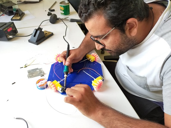
Electrical Connections
Now it is time to make electrical connections. Fix the Atmega 32U4, motor driver, BT board and power supply board to the bottom. Connect motors with motor driver. Connect the Microcontroller with motor driver board, HC-05 board, servo motor along with power supply board with Esp32-cam board and other components using pin connections chart given below.
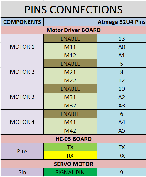
Connections
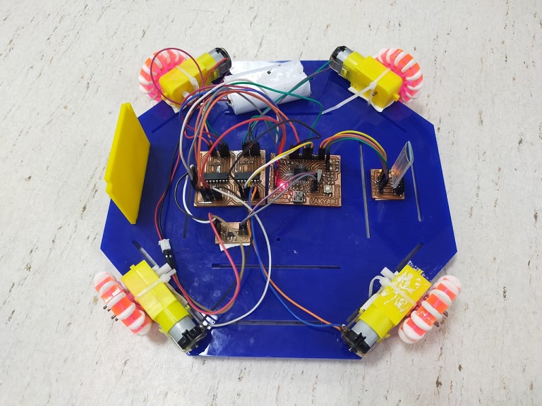
Testing the Robot
3D desiging the holder for Esp32-cam
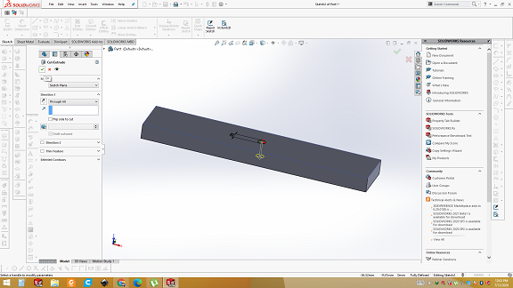
Esp32-cam needs to be fixed on servo motor so that we can control the viewing angle of video. For that we need holder in which Esp32-cam can be fixed and holder can be attached with motor. First of all, open the solid works and draw the base plat. Extrude it to 3mm. Draw a circle for the hole on its center. 2mm diameter circle is drawn then extrude cut through the plate. Through this, hole Holder is connected with servo motor.
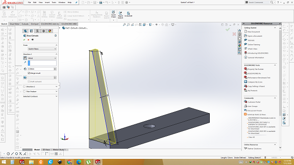
Now build the side support in which Esp32-cam board can be slide in and get fixed.
3D printing the Holder
Now save the file as .stl and open it into cura. Generate the gcode and give it to the 3D printer.
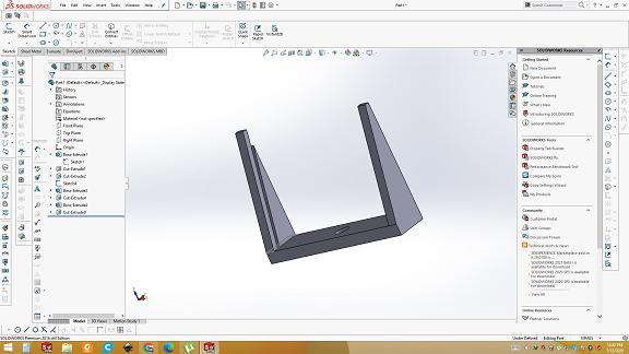
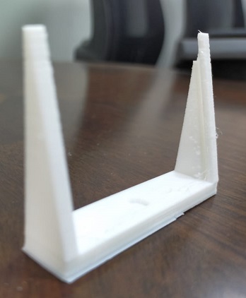
Final result
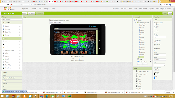
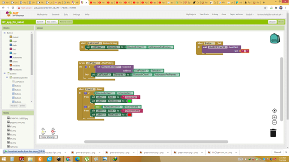
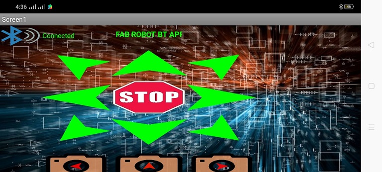
Bluetooth Mobile app for controlling Fab robot
Last part of final project is Mobile app for controlling my Fab robot. I made this app in the Application and interfacing week. I used MIT app inventor. It is open source platform for mobile app development. MIT app inventor uses block programming which make it much easier, especially for those who have no experience in app making like me. First of all, layout is designed, then programming is done in block codes. Step by step details of designing, coding and testing of this app are available here.
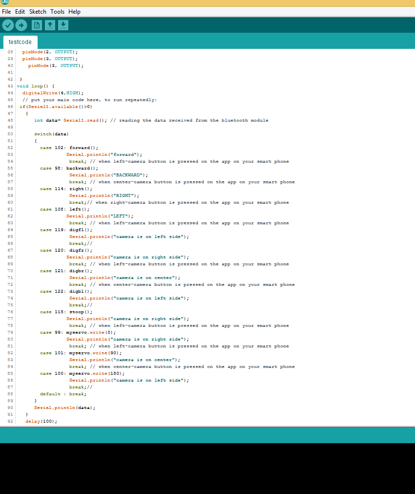
Embedded programming
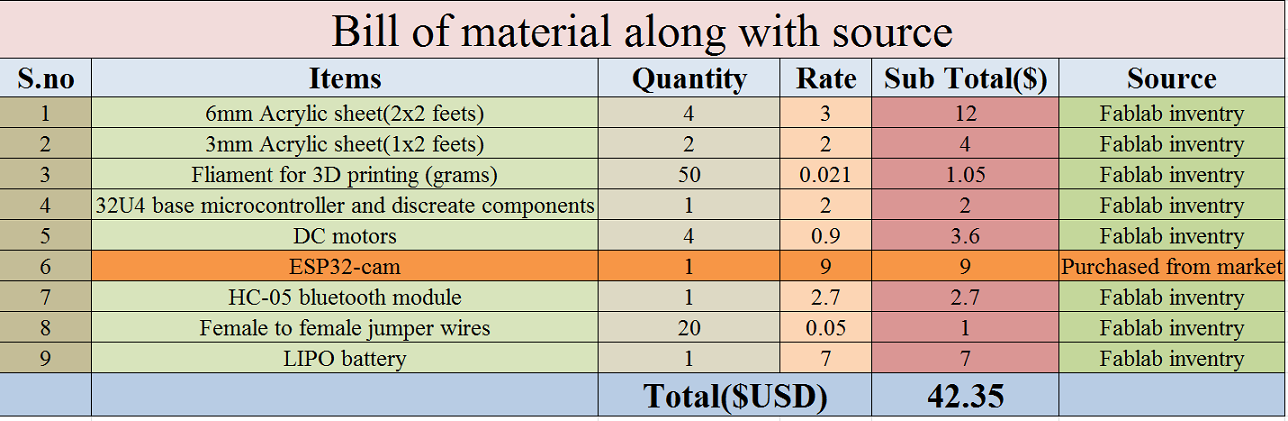
Bill of Material
 Download all files from here
This work is licensed under a Creative Commons Attribution-NonCommercial-ShareAlike 4.0 International License.