Group Assignment : Reading Data sheet and Architectures.
In this Group assignement we have study about data Sheet and Architecture of Micro Controller.
Introduction to AVR Microcontroller
Microcontroller is the advanced version of microprocessors. It contain on chip central processing unit (CPU), Read only memory (ROM), Random access memory (RAM), input/output unit, interrupts controller etc. Therefore a microcontroller is used for high speed signal processing operation inside an embedded system. It acts as major component used in designing of an embedded system.
AVR microcontroller is an electronic chip manufactured by Atmel, which has several advantages over other types of microcontroller. We can understand microcontroller by comparing it with Personal Computer (PC), which has a motherboard inside it. In that motherboard a microprocessor (AMD, Intel chips) is used that provides the intelligence, EEPROM and RAM memories for interfacing to the system like serial ports, display interfaces and disk drivers. A microcontroller has all or most of these features built into a single chip, therefore it doesn’t require a motherboard and any other components, Click.
AVR microcontroller comes in different configuration, some designed using surface mounting and some designed using whole mounting. It is available with 8-pins to 100-pins, any microcontroller with 64-pin or over is surface mount only.
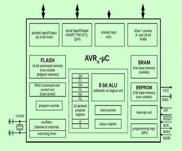
CPU: The CPU has an 8 bit ALU with status register, stack pointer, and 32 general purpose register. 8 GPR can be used as 16 bit register; 3 of the double register as address pointer (X, Y, Z). The GPR are part of the SRAM and thus volatile, meaning they lose their content without power, and are not defined when power returns!.
Control Unit: The RISC command and control unit with program counter can treat most 16 bit commmands (instructions) in one clock cycle. We reach near 16 million instructions per second ([MIPS]) Instructionspersecond#Millionsofinstructionspersecond_(MIPS)) with a 16 MHz crystal (about the speed of an INTEL 80386 in 1990).
Input/Output: Depending on the controller we get from one to four 8-bit GPIO ports, 8- and 16-bit timer/counter, a real time clock (RTC), PWM outputs, external interrupts, serial interfaces (EIA232, I²C(TWI), SPI), analog to digital converter (ADC), USB.
Memory: Three memory blocks are available. Non-volatile 16-bit Flash program memory, a little non-volatile 8-bit EEPROM an the volatile 8-bit SRAM. We will look in detail at these memories in this chapter.
Crystal: With an internal RC-oscillator we can get a clock up to 8 MHz. With an external crystal we can push the clock up to 20 MHz (even more with an internal PLL). A watchdog timer helps to detect an recover from hardware fault or program errors.
Interrupt unit: An interrupt handler manages external and internal interrupts to handle different events. The controller can use up to six sleep modes.
Programming logic: The controller memory (FLASH, EEPROM, fuse and lock-bits) can be programmed and cleared over SPI (Serial Peripheral Interface) in-system (ISP), Click.
AVR's are available in many different housings, and can use voltages from 1.8 V to 5.5 V. Apart from ISP they can be programmed using bootloader (Arduino) or debugged over JTAG.
Special Microcontroller Features:
PIC Micro Controller
PIC is a Peripheral Interface Microcontroller which was developed in the year 1993 by the General Instruments Microcontrollers. It is controlled by software and programmed in such a way that it performs different tasks and controls a generation line. PIC microcontrollers are used in different new applications such as smartphones, audio accessories, and advanced medical devices.There are many PICs available in the market ranging from PIC16F84 to PIC16C84. These types of PICs are affordable flash PICs. Microchip has recently introduced flash chips with different types, such as 16F628, 16F877, and 18F452. The 16F877 costs twice the price of the old 16F84, but it is eight times more than the code size, with more RAM and much more I/O pins, a UART, A/D converter and a lot more features..for more details PIC mirco Controller list is here and Detils, Click HERE
PIC Microcontrollers Architecture.
The PIC microcontroller is based on RISC architecture. Its memory architecture follows the Harvard pattern of separate memories for program and data, with separate buses.for the data Sheets Click Click HERE
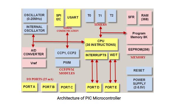
Memory Structure
The PIC architecture consists of two memories: Program memory and Data memory.
Program Memory: This is a 4K*14 memory space. It is used to store 13-bit instructions or the program code. The program memory data is accessed by the program counter register that holds the address of the program memory. The address 0000H is used as reset memory space and 0004H is used as interrupt memory space.
Data Memory: The data memory consists of the 368 bytes of RAM and 256 bytes of EEPROM. The 368 bytes of RAM consists of multiple banks. Each bank consists of general-purpose registers and special function registers.
Advantages of PIC Microcontroller:
Disadvantages of PIC Microcontroller:
Individual Assignment:
1. Read a Microcontroller Data Sheet
(Atmega 32U4 Microcontroller)
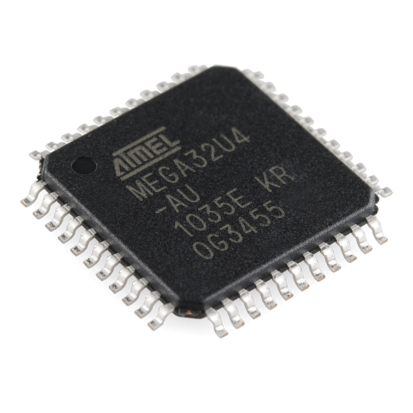
The ATMega32U4 is Atmel's low-power 8-bit AVR RISC-based microcontroller featuring 32KB self-programming flash program memory,
/2.5KB SRAM, 1KB EEPROM, USB 2.0 full-speed/low speed device, 12-channel 10-bit A/D-converter, and JTAG interface for on-chip-debug.
This is the same controller that's used on the Pro Micro and Fio v3.
Source:Sparkfun
Additional Features
- USB 2.0 Full-speed/Low Speed Device Module with Interrupt on Transfer Completion
- Complies fully with Universal Serial Bus Specification Rev 2.0
- Supports data transfer rates up to 12Mbit/s and 1.5Mbit/s
- Endpoint 0 for Control Transfers: up to 64-bytes
- Six Programmable Endpoints with IN or Out Directions and with Bulk, Interrupt or Isochronous Transfers
- Configurable Endpoints size up to 256 bytes in double bank mode
- Fully independent 832 bytes USB DPRAM for endpoint memory allocation
- Suspend/Resume Interrupts
- CPU Reset possible on USB Bus Reset detection
- 48MHz from PLL for Full-speed Bus Operation
- USB Bus Connection/Disconnection on Microcontroller Request
- Crystal-less operation for Low Speed mode
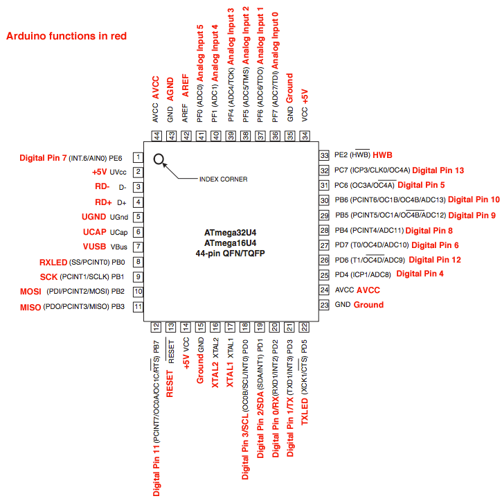
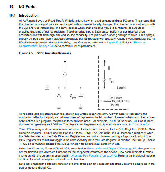
Atemgga 32U4 Microcontroller pinout
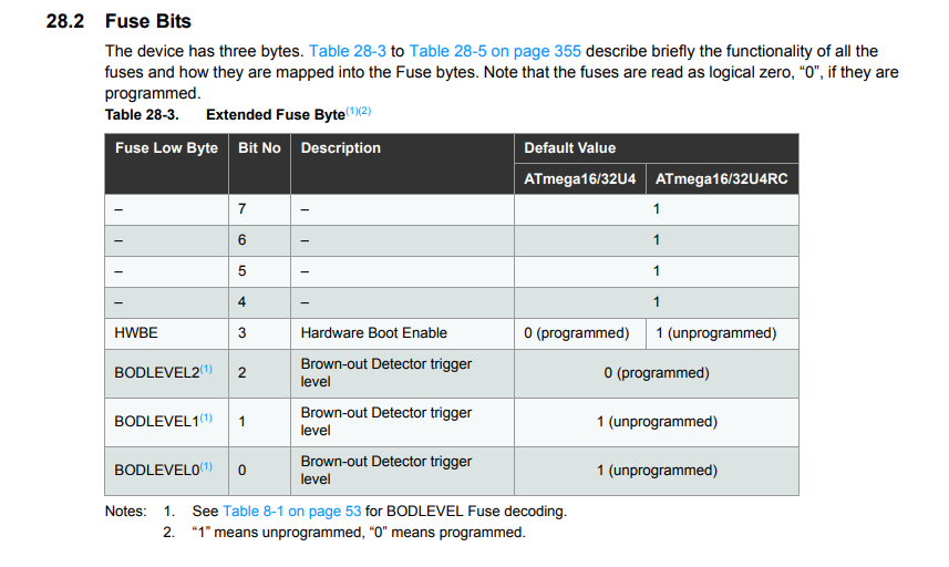
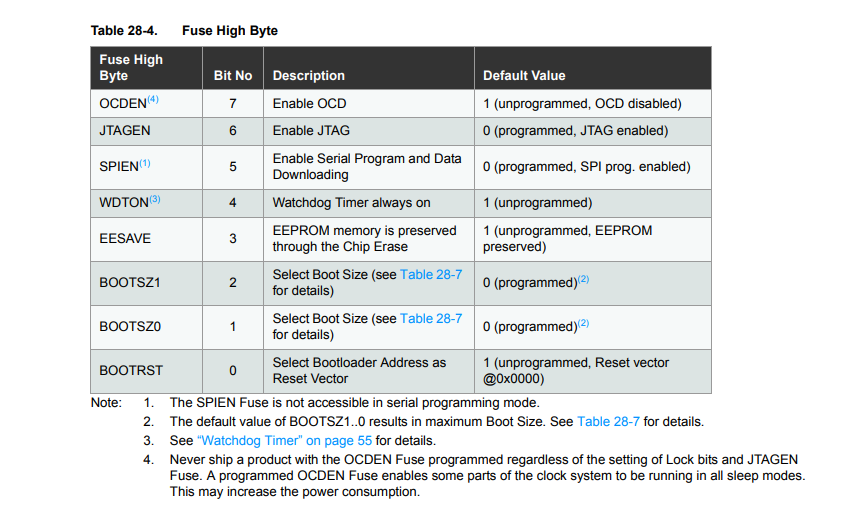
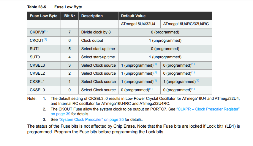
Atemgga 32U4 Microcontroller Fuses
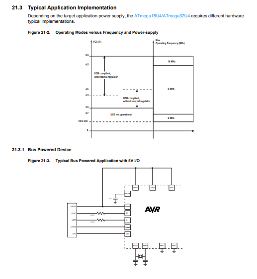
Atemgga 32U4 Microcontroller typical applications
Atemgga 32U4 Microcontroller-HOW TO TALK DIRECTLY TO THE CHIP REGISTERS
Download the data sheet from here
2. Program your board to do something
In this week I got inspiration from my colleague Nadir Aliwho has passed out in Fab Academy in 2018. He also made ATMega32U4 breakout board so I followed him. Best thing of 32U4 microcontroller is that it is directly programmable using the USB mini. We do not need FDTI cable to program it. It also has good number of I/O pins so it can be interface with many sensors and actuators at a time.
Following are the steps to design the 32U4 board
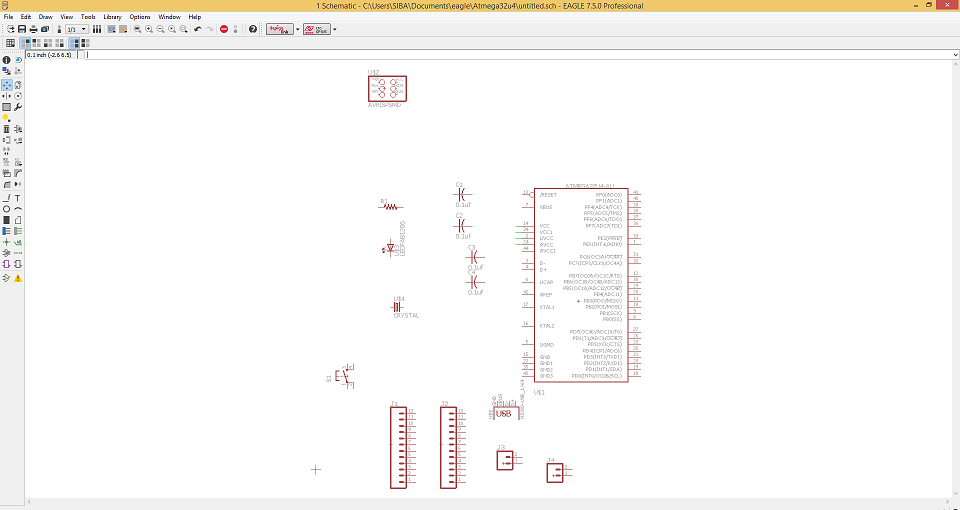
Opened Eagle software and import the MC package in Schemetic
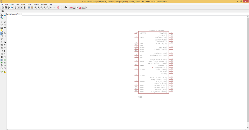
Import all the components in Schemetic
Connect them all in Schemetic
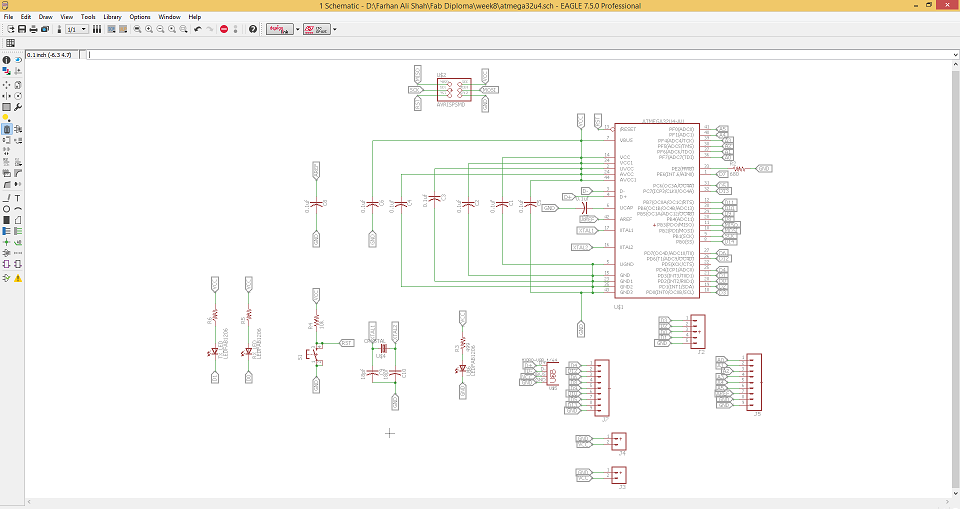
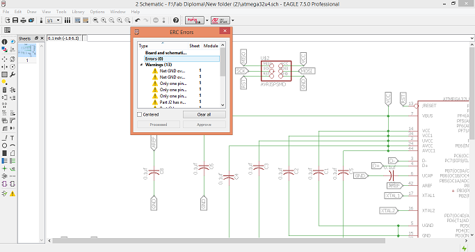
Check ERC
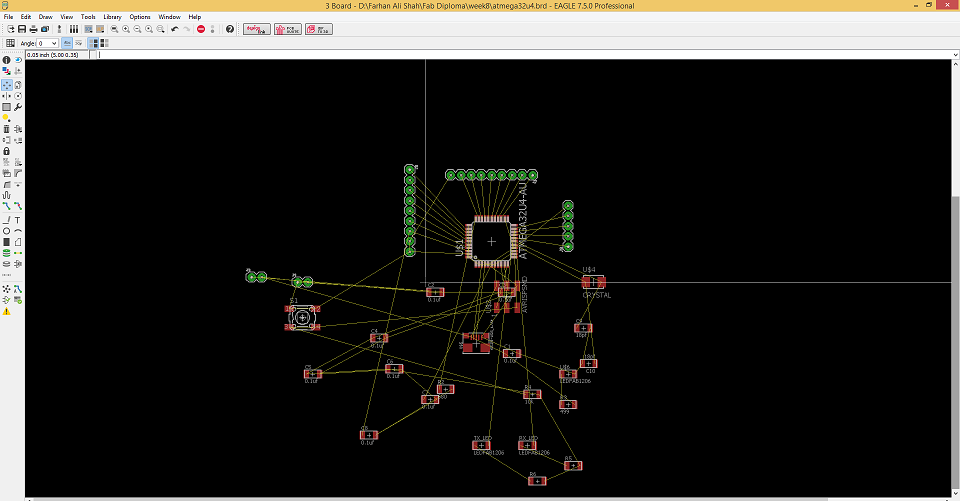
Go to board layout and rout the circuit
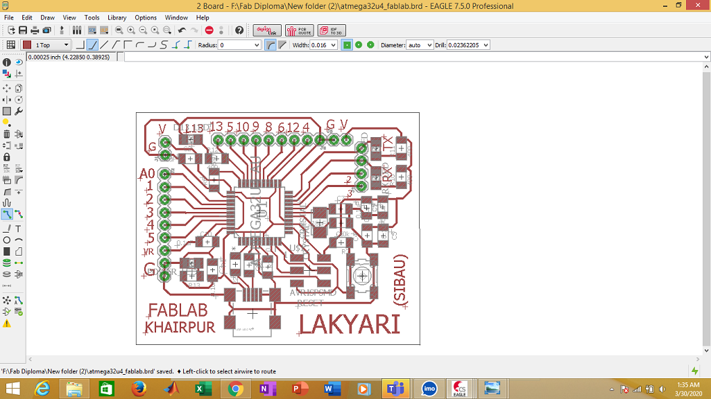
After routing
DUE TO CORONA VIRUS, LAB IS CLOSED. I AM HOPEFULL WITHIN COUPLE OF DAYS I WILL GET THE SPECIAL PERMISSION TO ACCESS THE LAB, SO I COULD MAKE THE BAORD AND PROGRAM IT.
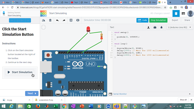
TILL THEN I TRIED TO SIMULATE IN TINKERCAD
But I really don't enjoy. It is super basic.
Now I got the partial access of the lab. Lets resume the work.
During lockdown, I completed my design work. Now I am in lab to mill the board.
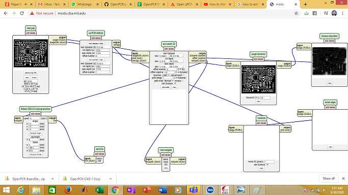
Opend mods
Open mods and import the PNG of Trace and drill and outline of the circuit. For trace, select 1/64 tool bit and generate the RML file.
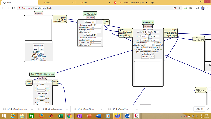
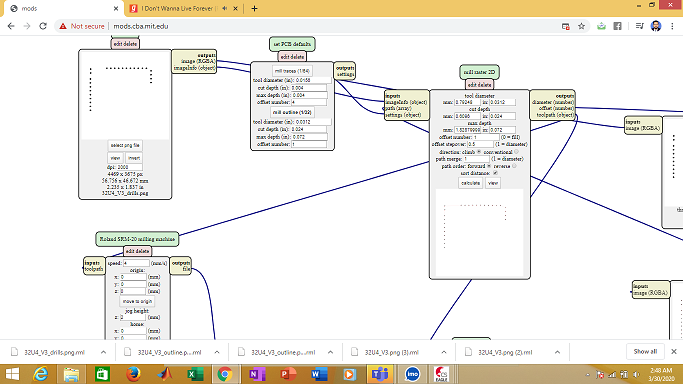
RML of drill and outline
Repeat the same process for drill and outline, but select the 1/32 tool bit and generate separate RML for drills and outline.
Machining
Open the SRM and manually set the X, Y and Z coordinates of start point. Then first give the trace file (1/64 tool bit) to machine. After trace is complete, change the tool bit with 1/32 tool bit and give the drills file then outline rml file.
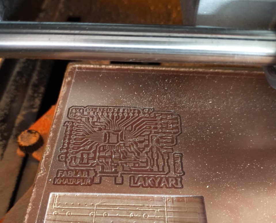
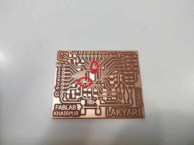
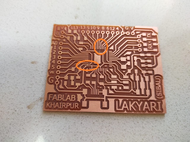
PCB milled
Check the milled PCB and observe that encircled two lines are connected which are not desired. So take the surgical knife and carefully separate these two lines. Now PCB looks fine.
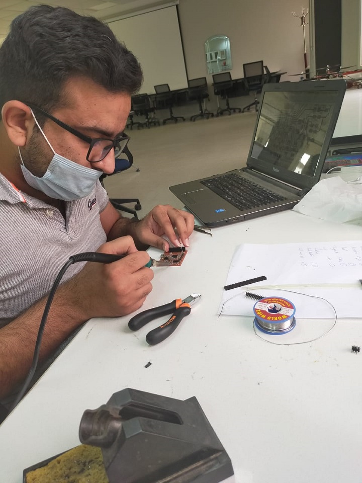
SOldering the IC
First of all start soldering the IC. This is main component of any circuit. 32U4 is Quad IC and special care is needed to solder the IC.
SOldering the other components
Always solder the smaller components first and components in the middle then go outside.
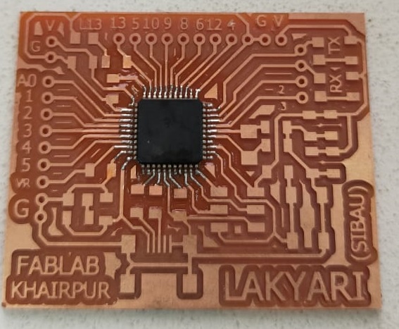
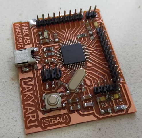
Atmega 32U4 board
here is final milled and soldered board of Atmega32U4.
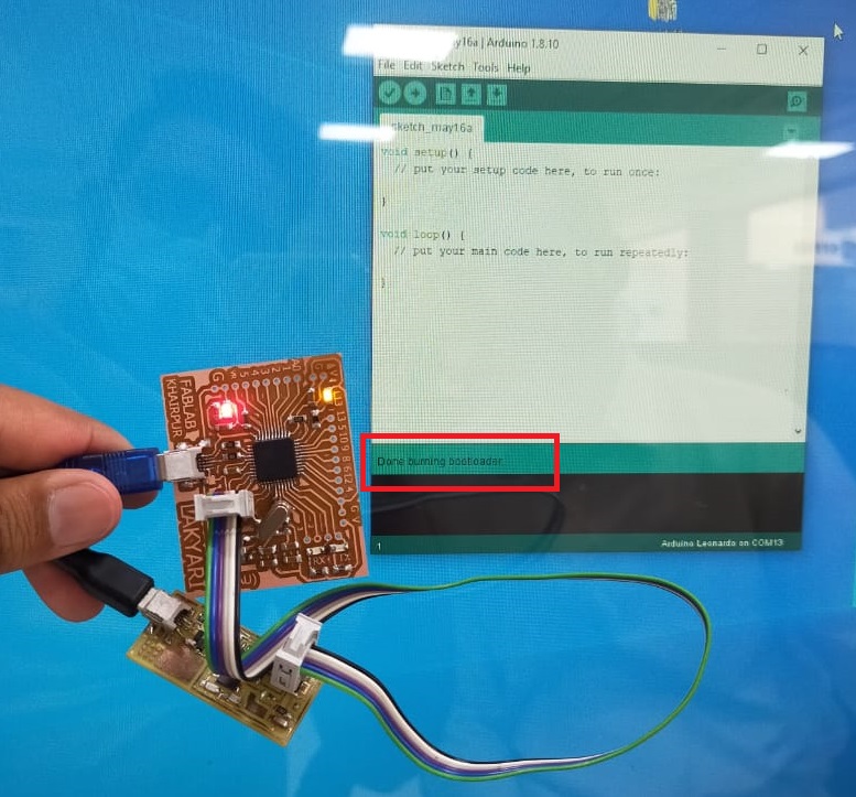
Boatload the IC
This board will not work until we will boatload the IC. We use the tinny 44 programmer which we made in Electronics production week to boatload the Atmega 32U4. Connect Tinny 44 with 32U4 board using ribbon cable and also connect both boards to the PC via USB cable. Open Arduino IDE and Go to the "Tools" option and select the board tinny 44 and programmer "USB tinny as ISp" and click burn boat loader. Wait for few seconds. Boatload is done as shown in highlighted area. Now our circuit is ready for programming.
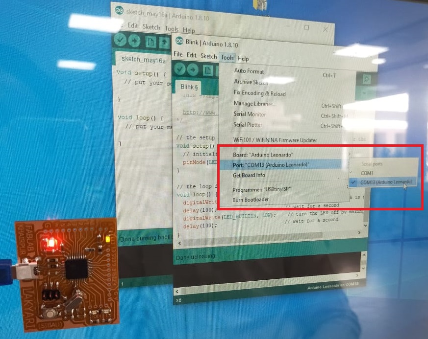
Verify the board
We can verify the board by just connecting USB mini to USB port of computer. Open the Arduino IDE and go to ports. In ports we can see the Arduino Leonardo board. Now we can program the board.
Program the Board
In this week our task is to program the microcontroller board using different environment. First and important platform is
Arduino IDE. It open source very easy platform to program the microcontroller boards. It works on C like programming. It is very user friendly.
Let’s start...
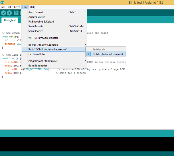
Open the Arduino IDE. Write the code. I have written basic Led blinking code to test the board. Select the board and com port in the tools.
Then click upload.
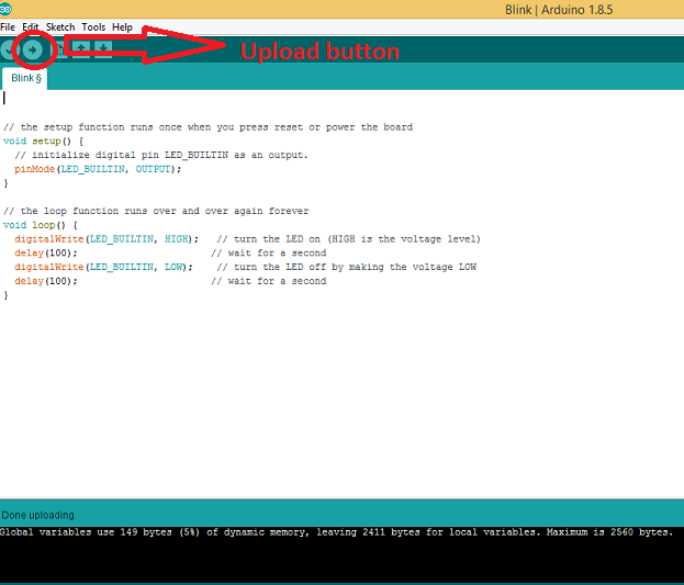
Final result
Controlling the servo motor using Serial monitor
Connect the servo motor with Microcontroller. Connect the data pin of servo with MC's digital pin 9. provide external supply of 12v and make ground common. upload the below code to the Atmega32U4 microcontroller.
CODE
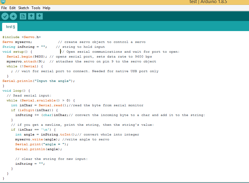
		#include"Servo.h"   //"" represent the greater and less sign here


		Servo myservo;           	 // create servo object to control a servo


		String inString = "";    	// string to hold input


		void setup() {

									// Open serial communications and wait for port to open:


		Serial.begin(9600); 		// opens serial port, sets data rate to 9600 bps


		myservo.attach(9);  		// attaches the servo on pin 9 to the servo object


		while (!Serial) {

						; 			// wait for serial port to connect. Needed for native USB port only

		}


		Serial.println("Input the angle");


		}


		void loop() {

											// Read serial input:

		while (Serial.available() > 0) {

		int inChar = Serial.read();			//read the byte from serial monitor


		if (isDigit(inChar)) {

		inString += (char)inChar;			// convert the incoming byte to a char and add it to the string:

		}

											// if you get a newline, print the string, then the string's value:

		if (inChar == '\n') {

		int angle = inString.toInt();		// convert whole into integer

		myservo.write(angle);				//write angle to servo

		Serial.print("angle = ");

		Serial.println(angle);


											// clear the string for new input:

      inString = "";

    }

  }

}
result
Other programming enviroment
In this week our task was to program the microcontroller using various programming platforms. So the 2nd platform that I am trying to use is a Python. I am programming my board using famous package/library called pyfirmita from python.
Firmata
Firmata is a generic protocol for communicating with microcontrollers from software on a host computer. It is intended to work with any host computer software package. Right now there is a matching object in a number of languages. It is easy to add objects for other software in order to use this protocol. Basically, this firmware establishes a protocol for talking to the Arduino from host software. The aim is to allow people to completely control the Arduino from software on the host computer.
Following are steps to program the Firmata
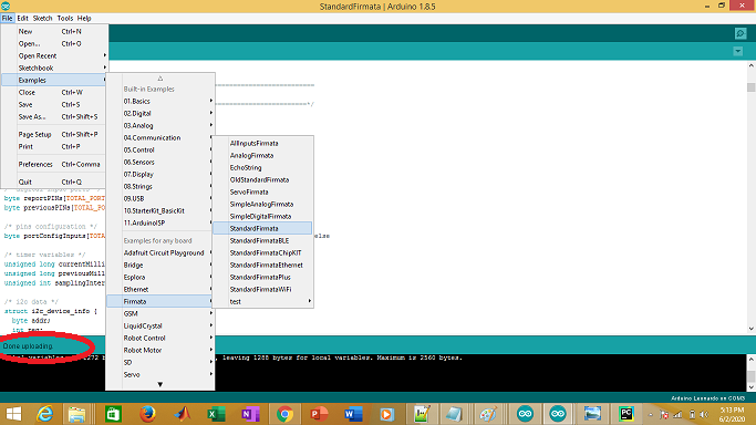
Firmata through Arduino IDE
Open Arduino IDE and go to File. Click on example then go to Firmata and select the Standard Firtmata (as show in picture). Then go to Tool and select the board and Port. Then click upload.
Now atmega32u4 is ready to communicate with python. Download and install the python. There are so many editor of python are available but I like pycharm. You can download Pycharm from here. The best thing about pycharm is that, that we can easily import different packages and use it
Install packages in pycharm
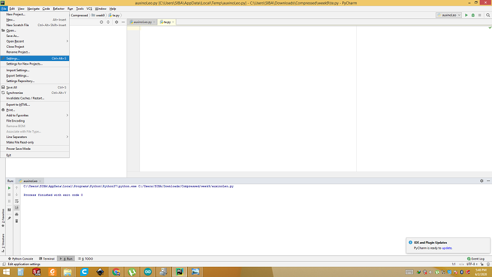
Click on File menu and select the setting.
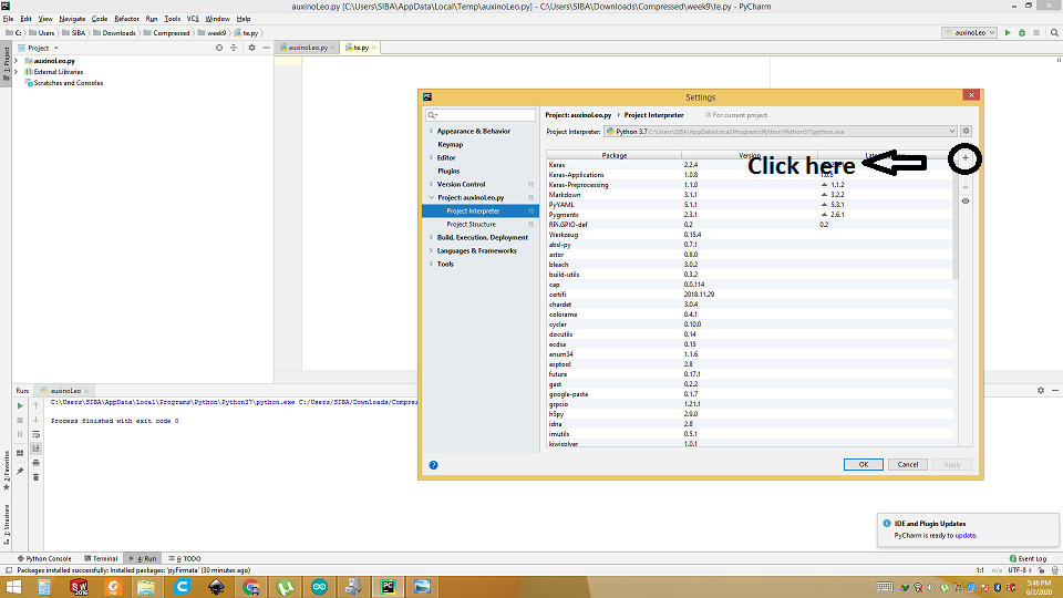
Click on Project interpreter and Click + sign
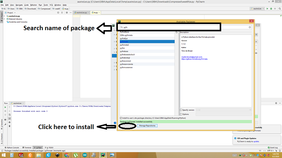
Search the "Pyfirmata", select it and click install. Once it is installed, it ready to use.
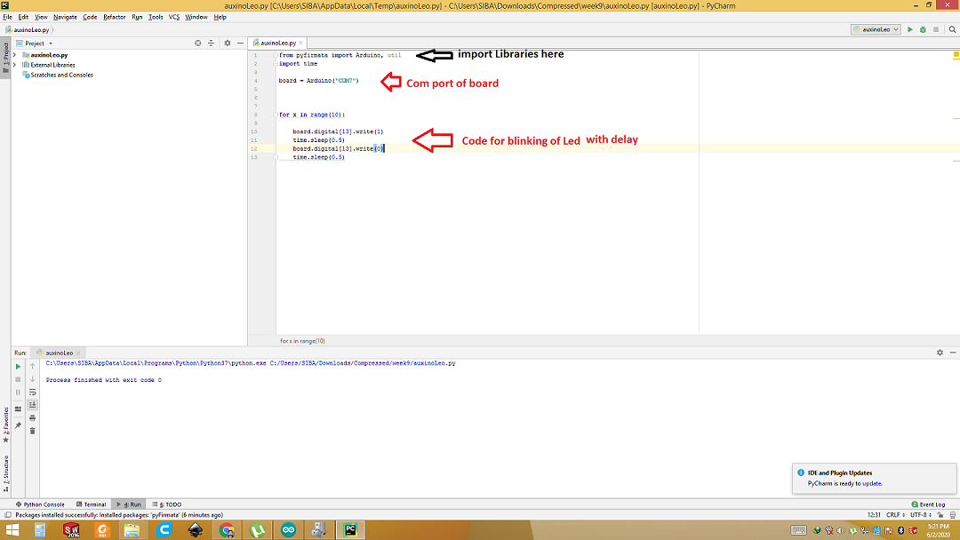
Coding in Python
I have worked in python before earlier also, so I did not find any difficulty in it. Here is the code in python. I wrote a simple code to turn on and off led for 10 times with 0.5 second delay.
Final result
Download all files from here

This work is licensed under a Creative Commons Attribution-NonCommercial-ShareAlike 4.0 International License.