Assignment
Week8: Embedded Programming
Assignment
- group assignment
- Compare the performance and development workflows for different microcontroller families
- individual assignment
- Read the datasheet for the microcontroller you are programming
- Program the board you have made to do something, with as many different programming languages and programming environments as possible.
My Work
This week, I made boards of UPDI programmar and FTDI serial interface for writing and testing my board with AVR 1 Series (that I made as ATtiny1614 echo board as an assignment outcome in week of electronics design). I created program by Arudino (.ino) language and C language, then compile, write and test program using my boards.
Group Assignment
Compare the performance and development workflows for different microcontroller families(link )
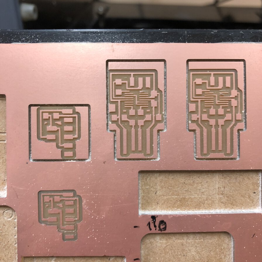
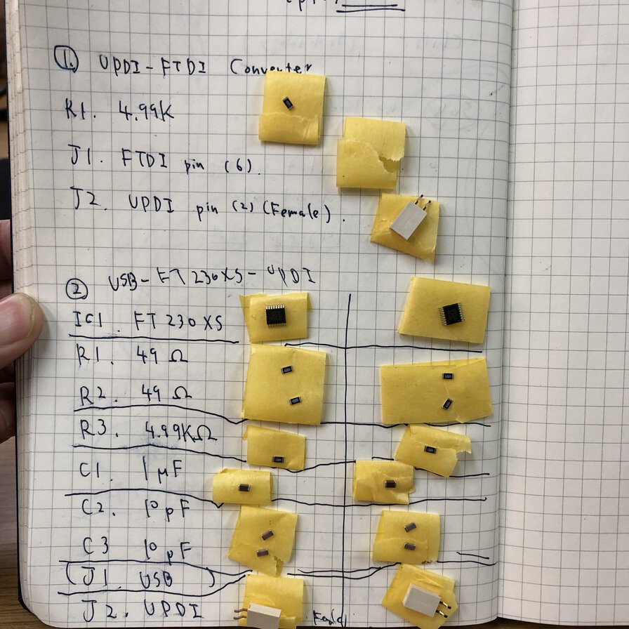
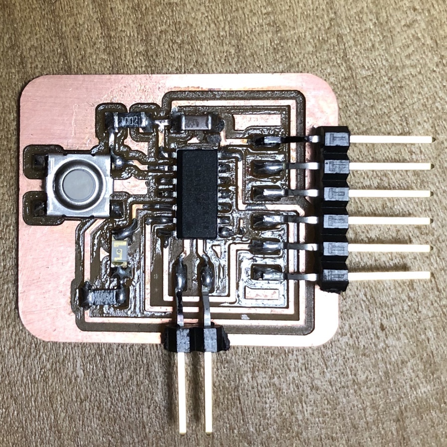
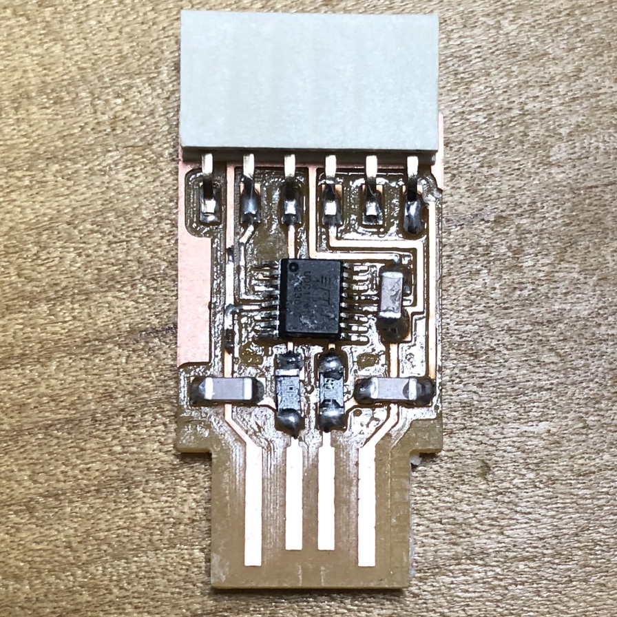
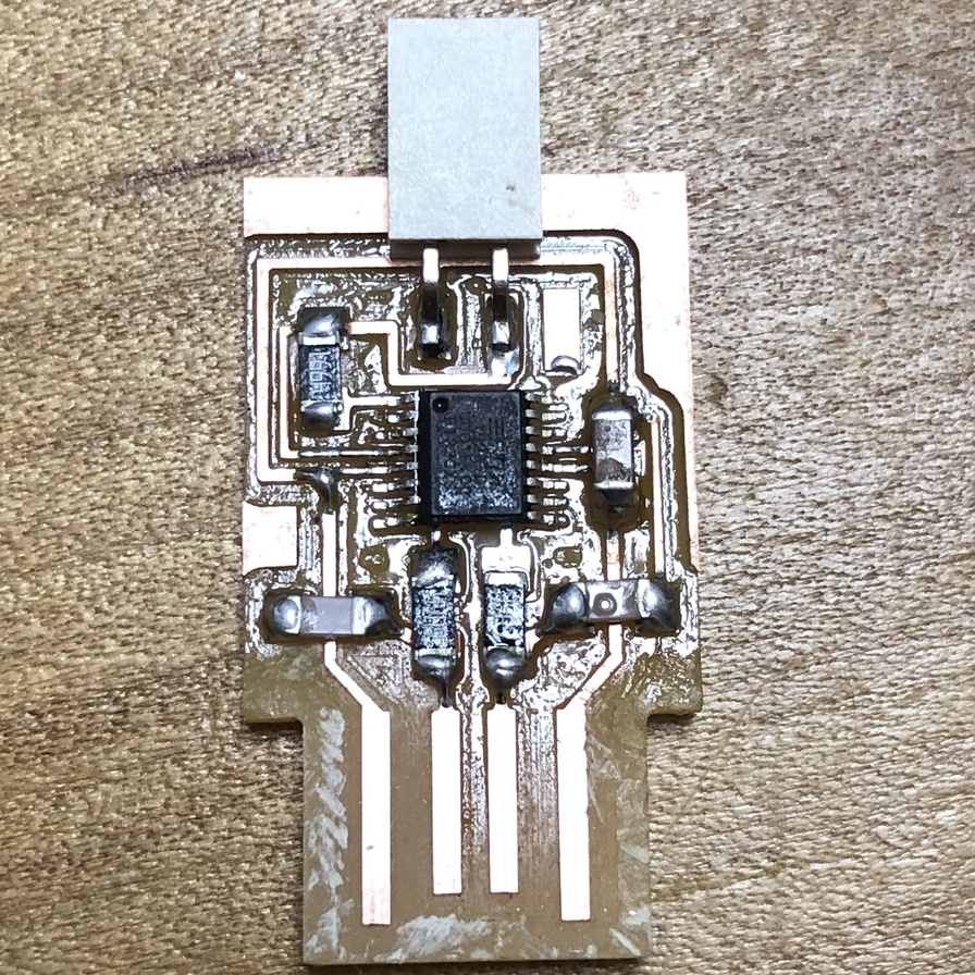
Boards production for AVR 1 series
In week of electronics design, I switched to ATtiny1614 echo board (AVR 1 series) and its UPDI programmer from ISP programmer. Accordingly, I started from making UPDI programmer(USB-FT230XS-UPDI), UPDI-FTDI converter and USB-FT230XS-serial converter. in this week.

Connection and test
At local session, the connection with my macbook pro did now work well. When I run ls /dev | grep -i usb, both of USB-FT230XS-UPDI(Programmer) and USB-FT230XS-Serial(Serial communication interface) were not listed.
Finally, it worked well after I came back to my home and renewed all the USB cables(that I bought in Amazon) and USB adapters(I bought at 100yen shop).
(To be updated) I will check the best environment (including RaspberryPi) for programming my board and pin that here
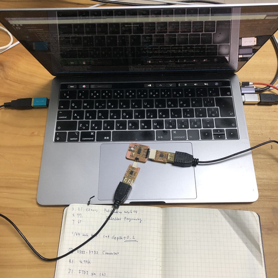
This is a way of a successful connection
USB Type C-A adapter - USB type A cable - USB-FT230XS-UPDI - Attiny1614 echo board - USB-FT230XS-Serial - USB type A cable - USB Type A-C adapter (host computer: Macbook pro)
$ ls /dev | grep -i usb
cu.usbserial-D307RG9Y (---USB-FT230XS-Serial)
cu.usbserial-D307RGA0 (---USB-FT230XS-UPDI)
tty.usbserial-D307RG9Y (---USB-FT230XS-Serial)
tty.usbserial-D307RGA0 (---USB-FT230XS-UPDI)
I have already written in detail about:
- How to build .hex file from .ino > here
- How to write program from linux > here
- How to write program from mac > here
Though I wanted to write a progarm by the same procedure to the same board, following errors occurred time by time:
- Exception: Failed to enter NVM programming mode
- Exception: Failed to chip erase using key
- Exception: Incorrect echo data
    ZTOKLIC02Z93YHLVDL:build tatsuro.homma$ pyupdi.py -d tiny1614 -c /dev/tty.usbserial-D307RGA0 -b 57600 -f hello.t1614.echo.ino.hex
    Device is locked. Performing unlock with chip erase.
    Traceback (most recent call last):
      File "/Users/tatsuro.homma/.pyenv/versions/3.7.0/bin/pyupdi.py", line 98, in _main
        nvm.enter_progmode()
      File "/Users/tatsuro.homma/.pyenv/versions/3.7.0/lib/python3.7/site-packages/updi/nvm.py", line 34, in enter_progmode
        if self.application.enter_progmode():
      File "/Users/tatsuro.homma/.pyenv/versions/3.7.0/lib/python3.7/site-packages/updi/application.py", line 129, in enter_progmode
        raise Exception("Failed to enter NVM programming mode")
    Exception: Failed to enter NVM programming mode

    During handling of the above exception, another exception occurred:

    Traceback (most recent call last):
      File "/Users/tatsuro.homma/.pyenv/versions/3.7.0/bin/pyupdi.py", line 178, in
        _main()
      File "/Users/tatsuro.homma/.pyenv/versions/3.7.0/bin/pyupdi.py", line 101, in _main
        nvm.unlock_device()
      File "/Users/tatsuro.homma/.pyenv/versions/3.7.0/lib/python3.7/site-packages/updi/nvm.py", line 54, in unlock_device
        self.application.unlock()
      File "/Users/tatsuro.homma/.pyenv/versions/3.7.0/lib/python3.7/site-packages/updi/application.py", line 89, in unlock
        raise Exception("Failed to chip erase using key")
    Exception: Failed to chip erase using key
      $ pyupdi.py -d tiny1614 -c /dev/tty.usbserial-D307RGA0 -b 57600 -f hello.t1614.echo.ino.hex
      Device is locked. Performing unlock with chip erase.
      Traceback (most recent call last):
        File "/Users/tatsuro.homma/.pyenv/versions/3.7.0/bin/pyupdi.py", line 98, in _main
          nvm.enter_progmode()
        File "/Users/tatsuro.homma/.pyenv/versions/3.7.0/lib/python3.7/site-packages/updi/nvm.py", line 34, in enter_progmode
          if self.application.enter_progmode():
        File "/Users/tatsuro.homma/.pyenv/versions/3.7.0/lib/python3.7/site-packages/updi/application.py", line 129, in enter_progmode
          raise Exception("Failed to enter NVM programming mode")
      Exception: Failed to enter NVM programming mode

      During handling of the above exception, another exception occurred:

      Traceback (most recent call last):
        File "/Users/tatsuro.homma/.pyenv/versions/3.7.0/bin/pyupdi.py", line 178, in
          _main()
        File "/Users/tatsuro.homma/.pyenv/versions/3.7.0/bin/pyupdi.py", line 101, in _main
          nvm.unlock_device()
        File "/Users/tatsuro.homma/.pyenv/versions/3.7.0/lib/python3.7/site-packages/updi/nvm.py", line 54, in unlock_device
          self.application.unlock()
        File "/Users/tatsuro.homma/.pyenv/versions/3.7.0/lib/python3.7/site-packages/updi/application.py", line 81, in unlock
          self._progmode_key()
        File "/Users/tatsuro.homma/.pyenv/versions/3.7.0/lib/python3.7/site-packages/updi/application.py", line 103, in _progmode_key
          self.datalink.key(constants.UPDI_KEY_64, constants.UPDI_KEY_NVM)
        File "/Users/tatsuro.homma/.pyenv/versions/3.7.0/lib/python3.7/site-packages/updi/link.py", line 215, in key
          self.updi_phy.send(list(reversed(list(key))))
        File "/Users/tatsuro.homma/.pyenv/versions/3.7.0/lib/python3.7/site-packages/updi/physical.py", line 85, in send
          raise Exception("Incorrect echo data")
      Exception: Incorrect echo data
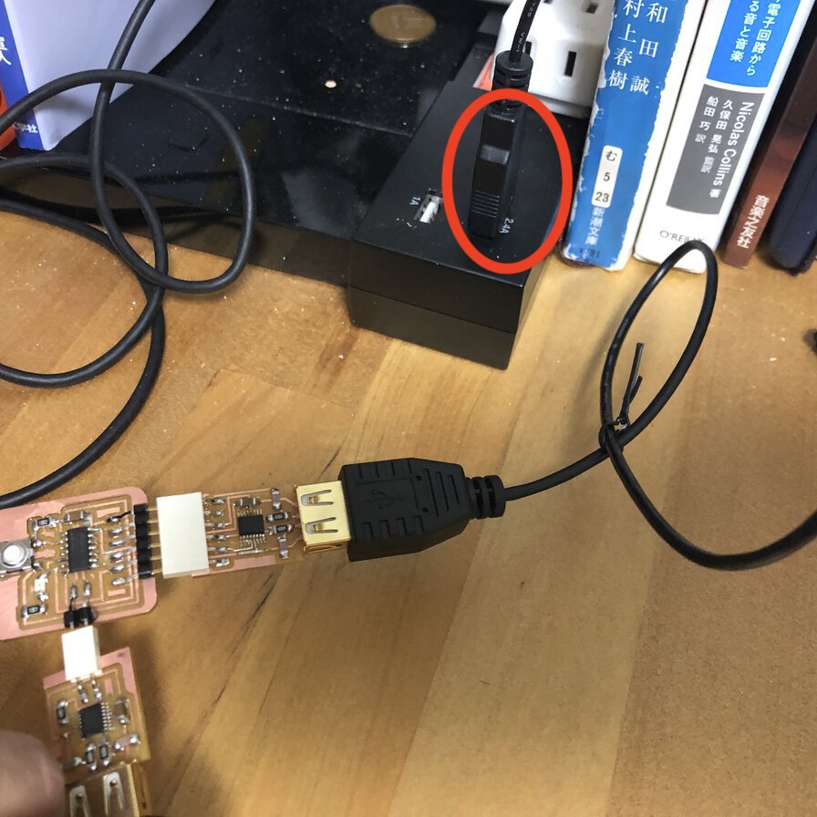
Seeing a issue thread in pyupdi github, these issue comes from power supply for target board via serial port of FTDI. So, I tried to put the USB cable to my room's quick battery charger port of 2.4A. Then this resolution works!
(In my case) it's important to have adapters and cables with strong joint. Also, it's necessary to sufficient power supply to the target board.
TBD: Check the power supply cases1: supply from USB type-C port in my macbook pro and case2: supply from 2.4A of quick charger for USB.
Read datasheet
I read the AVR ATtiny1614 datasheet and picked information that I'm interested in.
Architecture
Overview of tinyAVR 1-series is laying out memory sizes and pin count variant.
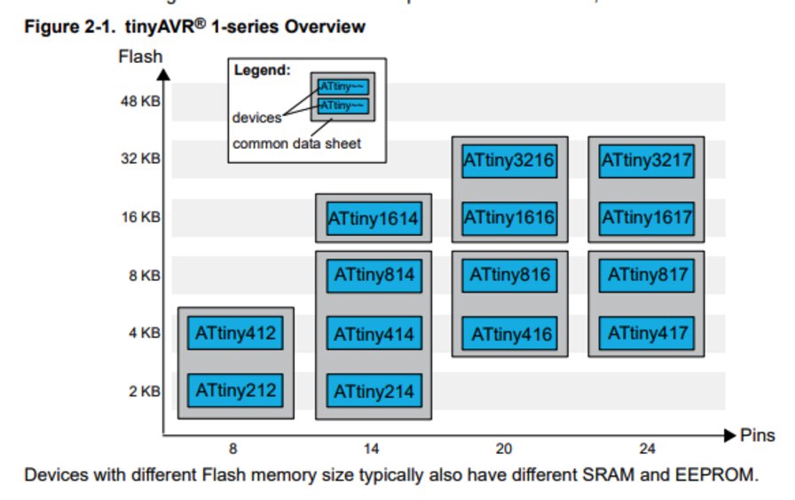
Refs: 2. tinyAVR 1-serires overview
ATtiny1614 has 16KB Flash memories and 14 pins.
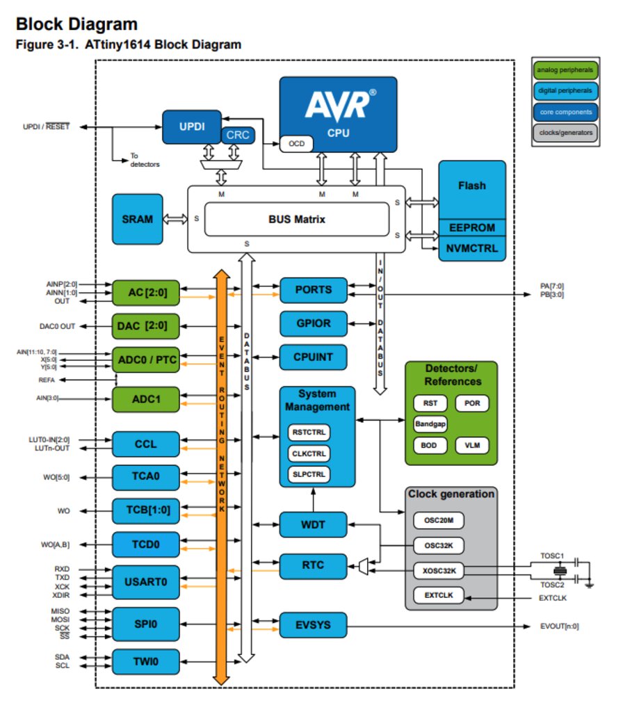
Refs: 3. Block Diagram
Refs: 8. AVR CPU - 8.3 Architecture
"In order to maximize performance and parallelism, the AVR CPU uses a Harvard architecture with separate buses for program and data. Instructions in the program memory are executed with single-level pipelining. While one instruction is being executed, the next instruction is prefetched from the program memory. This enables instructions to be executed on every clock cycle."
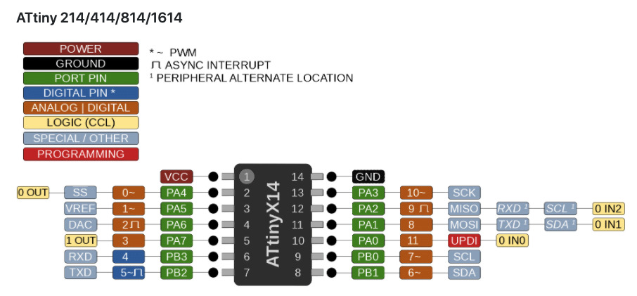
Pinout
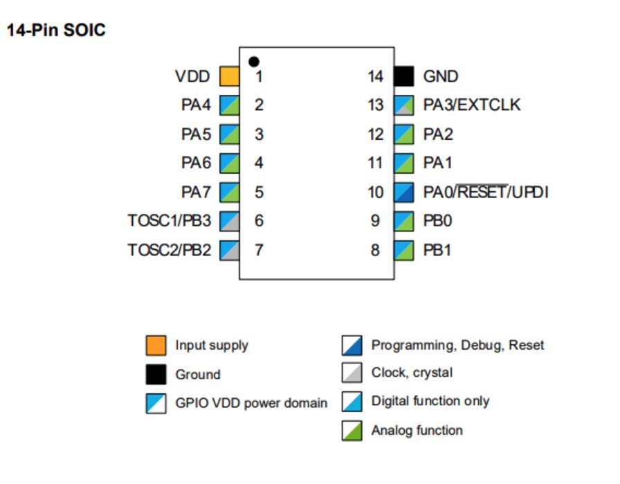
Refs: 4.1 14-Pin SOIC
Besides datasheet description, magaTinyCore's pin mapping is visualized at the following diagrams on the website of SpenceKonde(SpenceKonde/megaTinyCore(ATtiny_x14.md),
Memories
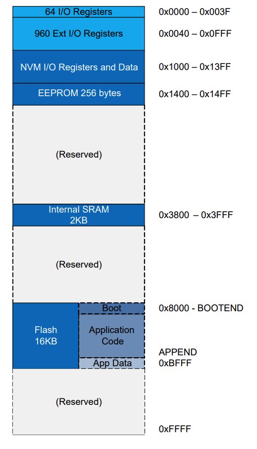
Refs: 6. Memories (6.1 Overview, 6.2 Memory Map)
- ERPROM: 256bytes
- SRAM: 2KB
- Flash: 16KB
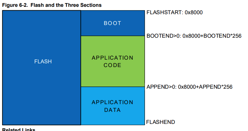
Flash has three sections(boot, application code and application data) for write protection.
Programming
Programming - Arduino (Sample: t1614.button.ino)
Refs: 4.1 14-Pin SOIC
Besides datasheet description, magaTinyCore's pin mapping is visualized at the following diagrams on the website of SpenceKonde(SpenceKonde/megaTinyCore(ATtiny_x14.md),
Refs: 6. Memories (6.1 Overview, 6.2 Memory Map)
- ERPROM: 256bytes
- SRAM: 2KB
- Flash: 16KB
Programming
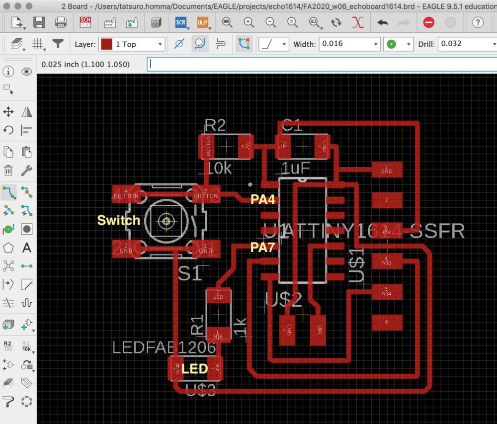
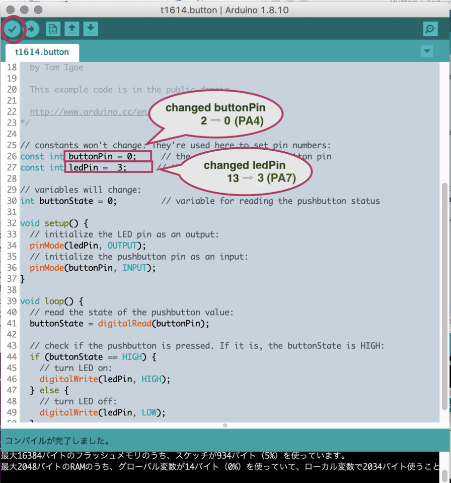
According to Pinout spec in datasheet,
- My LED connected PA7 of ATtiny1614, which is Arduino Pin 3
- My Switch connected PA4 of ATtiny1614, which is Arduino Pin 0
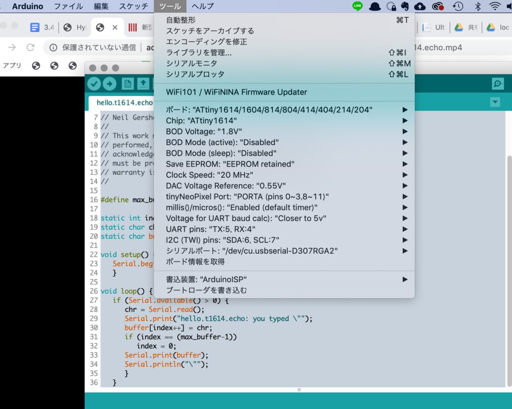
The deatil procedure is written in week06 document here(How to build .hex file from .ino)
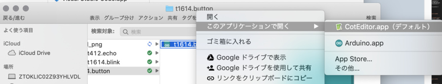
When setting the board as ATtiny1614, we cannot edit the .ino file in Arduino IDE. So you need to open .ino file by text editor.
Besides that, .ino file needs to be a directory with the same name as .ino - like "t1614.button/t1614.button.ino"
$ cd ~/Arduino/build
$ ls -1
build.options.json
core
includes.cache
libraries
preproc
sketch
t1614.button.ino.bin
t1614.button.ino.eep
t1614.button.ino.elf
t1614.button.ino.hex
t1614.button.ino.lst
// set local into virtual environment
$ pyenv local 3.7.0
// check the python version of virtual environment
$ pyenv versions
system
* 3.7.0 (set by /Users/tatsuro.homma/Arduino/build/.python-version)
3.7.0/envs/scraping
scraping
// Program .hex
$ pyupdi.py -d tiny1614 -c /dev/tty.usbserial-D307RGA0 -b 57600 -f t1614.button.ino.hex Programming successful
source file is ATtiny1614.button.ino
Programming - Arduino (t1614.button_blink.ino: blink and serial communication)
I tried to write a program to press button triggers toggling the frequency of blink
My idea is that 3 seconds of long push on the button triggers the change of frequency of blink in 4 status: 0: Nothing, 1: 100msec, 2:500msec, 3:1000msec. The status is sent to serial monitor.
Source code - Attiny1614.button_blink.ino
source file is ATtiny1614.button_blink.ino
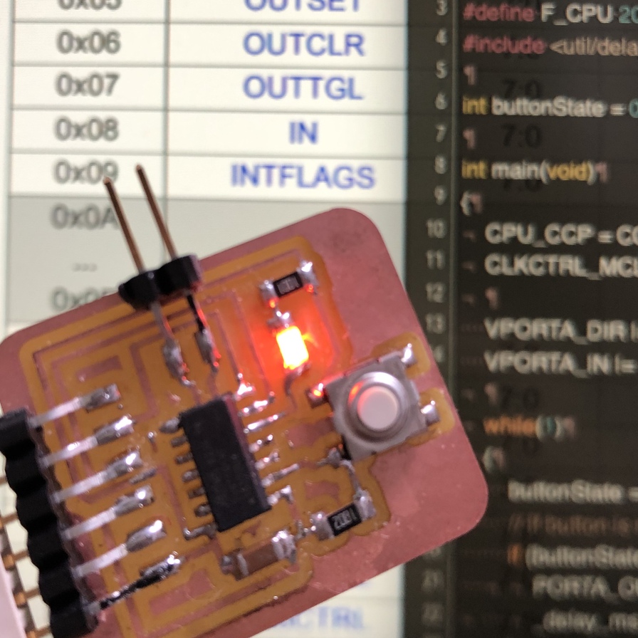
Programming - C (t1614.simpleblink.c)
It took time for me to dig in how to read datasheet of AVR 1 Series( to write a program and compile it into .hex file
Firstly, I tried to write a code based on echo.c for Attiny44. However it went wrong as the usage of register for In-Out pins are different between tiny44 and tiny1614(AVR 1 series). Based on little information for AVR 1 serires implementation, I managed to obtain a simple blink output sample source in a discussion forum. Then I added input pin setting and function to read status from button.
Tips
Datasheet of ATtiny1614 tells something.
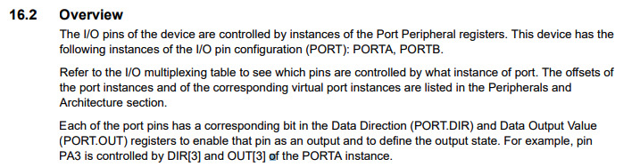
For accessing pin, it's necessary to access via port instance(e.g. PORTA)
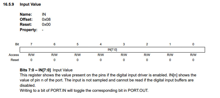
Input data can be derived from "IN" register.
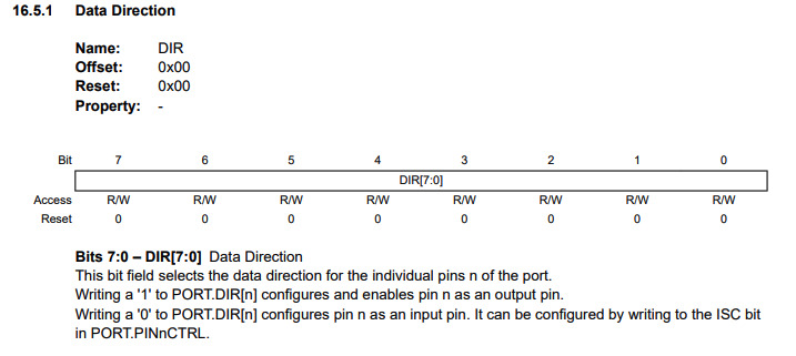
If "DIR" is set to 1, the assigned pin is used as output pin.
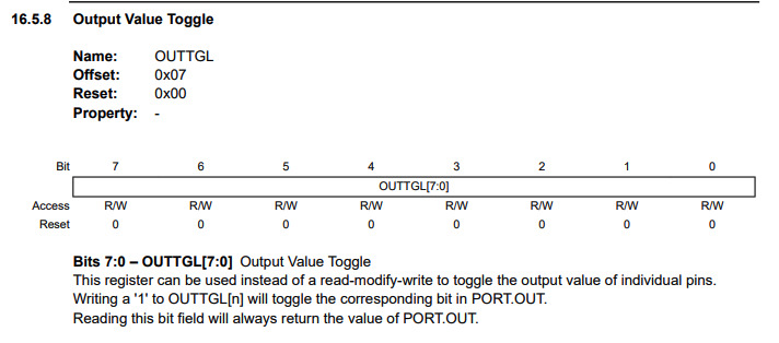
There are various function in register. For example, OUTTGL will toggle the corresponding bit in PORT.OUT.
It looks that register values in datasheet cannot be used in source code directly. So I checked the source code of avr/io.h and digged in avr/iotn1614.h
In my local environment, these files are located in following directories.
- ~/Library/Arduino15/packages/arduino/tools/avr-gcc/7.3.0-atmel3.6.1-arduino5/avr/include/avr/io.h
- ~/Library/Arduino15/packages/arduino/tools/avr-gcc/7.3.0-atmel3.6.1-arduino5/avr/include/avr/iotn1614.h
I'm not sure if there are more straight forward approaches.
Source code - Attiny1614.simpleblink.c
Build .hex file from C language program
As Arduino IDE cannot open .c source file, I tried to compile it by arduino-cli commandline tool.
What I did is:
- Install arduino-cli via homebrew
- Make configuration file
- Install a board of ATtiny1614
- Add 3rd party board manager
- Compile
- Write program by pyupdi
Refs: Arduino-cli
// then you can run command of arduino-cli like:
$ arduino-cli help core
Config file written to: /Users/tatsuro.homma/Library/Arduino15/arduino-cli.yaml
$ arduino-cli board list
Port                            Type              Board Name FQBN Core
/dev/cu.Bluetooth-Incoming-Port Serial Port       Unknown
/dev/cu.Kn-iphone-WirelessiAP   Serial Port       Unknown
/dev/cu.usbserial-D307RG9Y      Serial Port (USB) Unknown
/dev/cu.usbserial-D307RGA0      Serial Port (USB) Unknown
// list all board of Attiny
$ arduino-cli board listall Attiny
            Board Name                                         FQBN
ATtiny1614/1604/814/804/414/404/214/204            megaTinyCore:megaavr:atxy4
ATtiny1614/1604/814/804/414/404/214/204 (optiboot) megaTinyCore:megaavr:atxy4o
ATtiny1634 (No bootloader)                         ATTinyCore:avr:attiny1634
ATtiny1634 (Optiboot)                              ATTinyCore:avr:attiny1634opti
ATtiny167/87 (Optiboot)                            ATTinyCore:avr:attinyx7opti
ATtiny2313/4313                                    ATTinyCore:avr:attinyx313
ATtiny24/44/84                                     ATTinyCore:avr:attinyx4
ATtiny25/45/85                                     ATTinyCore:avr:attinyx5
ATtiny261/461/861                                  ATTinyCore:avr:attinyx61
ATtiny3216/1616/1606/816/806/416/406               megaTinyCore:megaavr:atxy6
ATtiny3216/1616/1606/816/806/416/406 (optiboot)    megaTinyCore:megaavr:atxy6o
ATtiny3217/1617/1607/817/807/417                   megaTinyCore:megaavr:atxy7
ATtiny3217/1617/1607/817/807/417 (Optiboot)        megaTinyCore:megaavr:atxy7o
ATtiny412/402/212/202                              megaTinyCore:megaavr:atxy2
ATtiny412/402/212/202 (optiboot)                   megaTinyCore:megaavr:atxy2o
ATtiny43                                           ATTinyCore:avr:attiny43
ATtiny44/84 (optiboot)                             ATTinyCore:avr:attinyx4opti
ATtiny441/841 (No bootloader)                      ATTinyCore:avr:attinyx41
ATtiny441/841 (Optiboot)                           ATTinyCore:avr:attinyx41opti
ATtiny45/85 (Optiboot)                             ATTinyCore:avr:attinyx5opti
ATtiny461/861 (optiboot)                           ATTinyCore:avr:attinyx61opti
ATtiny48/88                                        ATTinyCore:avr:attinyx8
ATtiny48/88 (optiboot)                             ATTinyCore:avr:attinyx8opti
ATtiny828 (No bootloader)                          ATTinyCore:avr:attiny828
ATtiny828 (Optiboot)                               ATTinyCore:avr:attiny828opti
ATtiny87/167 (No bootloader)                       ATTinyCore:avr:attinyx7
Attiny416 Xplained Nano (optiboot)                 megaTinyCore:megaavr:Xplained416
Attiny817 Xplained Mini (optiboot)                 megaTinyCore:megaavr:Xplained817
// install megaTinyCore(ATtiny1614)$ arduino-cli core install megaTinyCore:megaavr
// confirm installed board
$ arduino-cli core list
ID                   Installed Latest Name
ATTinyCore:avr       1.3.2     1.3.2
esp32:esp32          1.0.4     1.0.4
esp8266:esp8266      2.4.2     2.4.2
megaTinyCore:megaavr 1.1.5     1.1.5
$ vi ~/Library/Arduino15/arduino-cli.yaml
  board_manager:
    additional_urls:
      http://drazzy.com/package_drazzy.com_index.json
// update-index
$ arduino-cli core update-index
Updating index: package_index.json downloaded
Updating index: package_drazzy.com_index.json downloaded

$ arduino-cli core search ATtiny1614
ID                   Version Name
megaTinyCore:megaavr 1.1.8   megaTinyCore
Sketch uses 168 bytes (1%) of program storage space. Maximum is 16384 bytes.
Global variables use 0 bytes (0%) of dynamic memory, leaving 2048 bytes for local variables. Maximum is 2048 bytes.
$ ls
t1614.simpleblink.c
t1614.simpleblink.c.megaTinyCore.megaavr.atxy4.hex
t1614.simpleblink.c.megaTinyCore.megaavr.atxy4.elf
// Check programmar is recognized as USB device
$ ls /dev | grep -i usb
cu.usbserial-D307RGA2
cu.usbserial-FT9OZSKA
tty.usbserial-D307RGA2
tty.usbserial-FT9OZSKA
// Switch to pyenv virtual environment
$ pyenv local 3.7.0
$ pyenv versions
system
* 3.7.0 (set by /Users/tatsuro.homma/gdrive/Fab/FabAcademy2020/week08/file/t1614.simpleblink.c/.python-version)
3.7.0/envs/scraping
$ pyupdi.py -d tiny1614 -c /dev/tty.usbserial-D307RGA0 -b 57600 \
-f t1614.simpleblink.c.megaTinyCore.megaavr.atxy4.hex
Programming successful
Files
Lessons Learned
- It's very important to keep stable local environment for embedding program and verification. It's seems to be essential to supply sufficient current by AC adapter and tight joint (it might be the issue of my soldering performance).
- It's necessary to understand key feature like meory and registyer mapping in datasheet for writing efficient program especially in C language.
References
- Attiny1614 datasheet
- Attiny1614 datasheet(Japanese)
- SpenceKonde/megaTinyCore(ATtiny_x14.md)
- a simple blink output sample source in a discussion forum
- Arduino-cli