Assignment
Week6: Electronics Design
Assignment
- group assignment
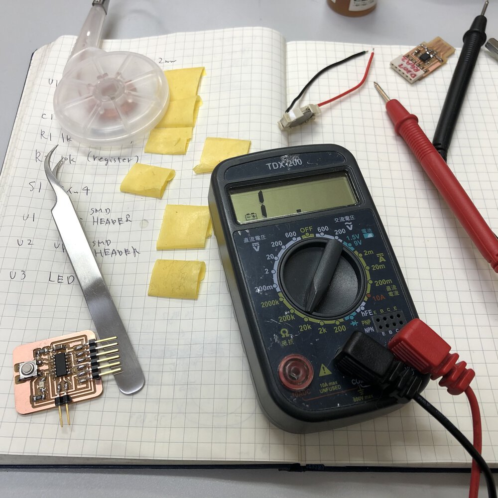
- Use the test equipment in your lab to observe the operation of a microcontroller circuit board (in minimum, check operating voltage on the board with multimeter or voltmeter and use oscilloscope to check noise of operating voltage and interpret a data signal)
- individual assignment
- Redraw one of the echo hello-world boards or something equivalent, add (at least) a button and LED (with current-limiting resistor) or equivalent input and output, check the design rules, make it, test it.
My Work
I tried to make Attiny1614 echo board using EAGLE software and Roland MDX-15. I made schematics and board pattern by EAGLE, milled it by Roland MDX-15, solder components, programmed it by UPDI programmer then tested echo program.
Group Assignment (use the test equipment to observe the operation of a microcontroller circuit board)
Board and Component
At global session in week4(Electronics Production), I was lucky to be reviewed about my FabTiny using ISP programer and Neil recommended me to use UPDI(AVR 1 series) or ARM as a programmer because these newer ones work in good performance and compatible to the USB connections. UPDI's knowledge looks to be shared the other people better than ARM. That's why I moved to UPDI from ISP from this week. For going thorough basic design of PCB, I decided to try Attiny1614 echo board.
Here is a datasheet of Attiny1614
Attiny1614 echo board is shared at FabAcademy Embedded programing page.
Here is a summary of component for the Attiny1614 echo board. The parts is less than ISP(AVR) programmer for Attiny44/45 etc. because AVR-1 series micro controller allows to program by UDPI interface (does not need to 2x3 pin ISP) and to omit the crystal because micro controller itself has internal / external clock options.
For the assessment requirement that says "add (at least) a button and LED (with current-limiting resistor) ", I decided to add LED, resister and switch to my board
| parts | description | amount |
|---|---|---|
| micro controller | ATtiny1614 | 1 |
| capacitor | 1uF | 1 |
| led | orange | 1 |
| switch | tact | 1 |
| resister | 1kΩ(for led) | 1 |
| resister | 10kΩ(for pull up register of switch) | 1 |
| pin header | 1x6 pin for FTDI | 1 |
| pin header | 1x2 pin for UPDI | 1 |
Schematic Design
- Supported by multiple environment of windows, mac os and linux.
- Free license is provided in order to private use and non profit activity by individual. A restriction of free license is under 2 sheet of circuits, under 2 layers of signal and under 80cm2.
- Supported by multiple environment of windows, mac os and linux.
- Owned by Autodesk Inc. and the models coordinate between Fusion 360 and EAGLE.
Select Component from Fab library
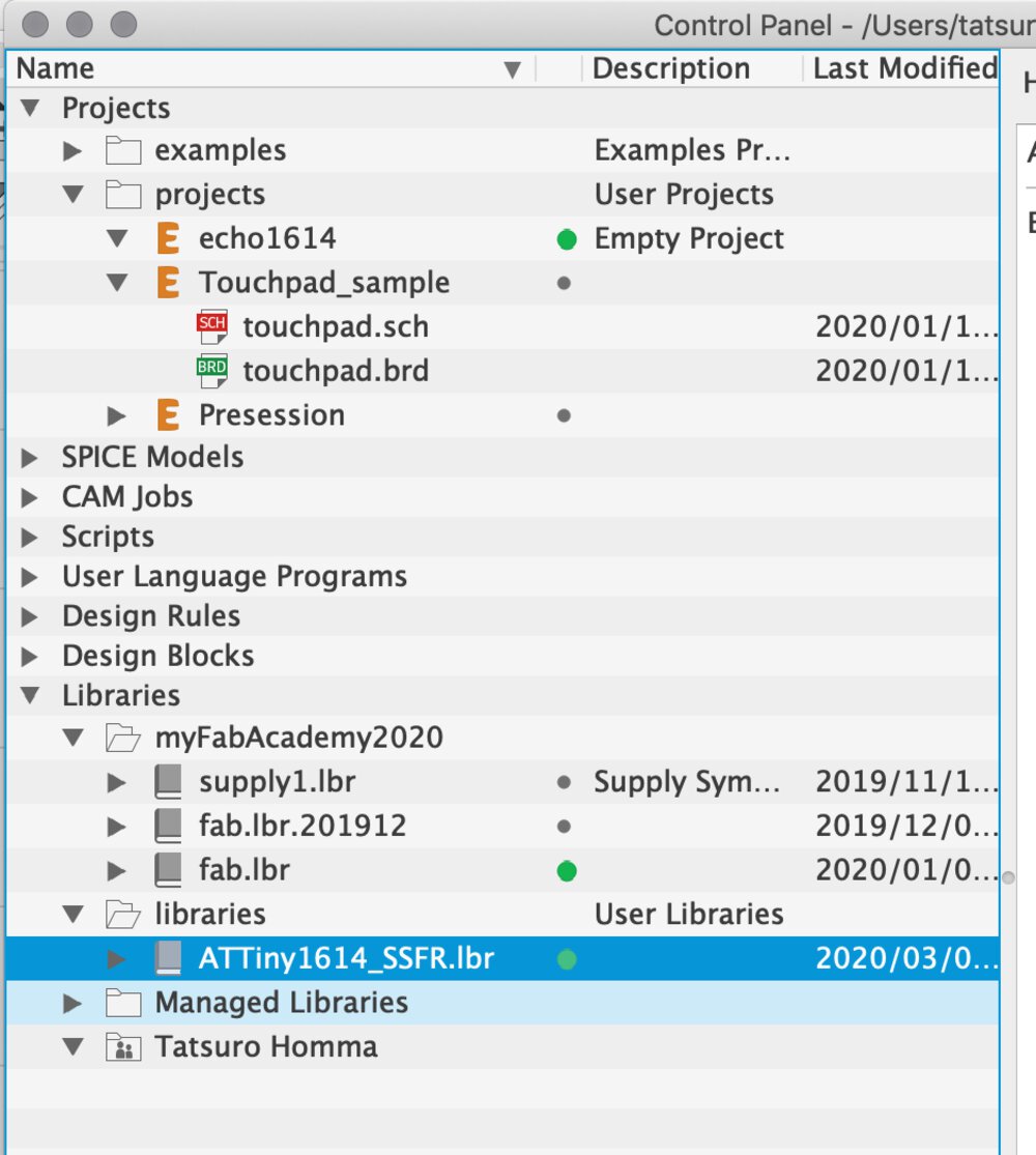
For redrawing the schematic, I needed to download libraries for EAGLE from Gitlab fab library.
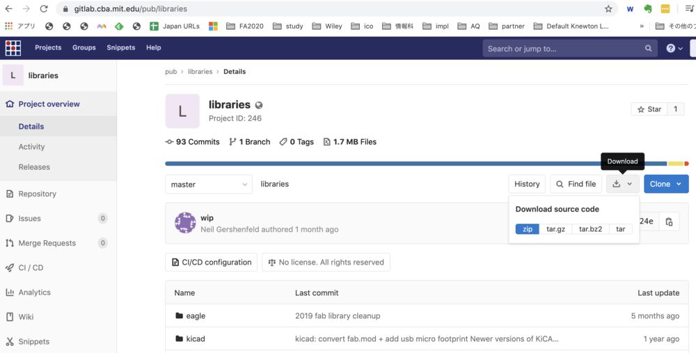
1) download libraries for EAGLE from gitlab,
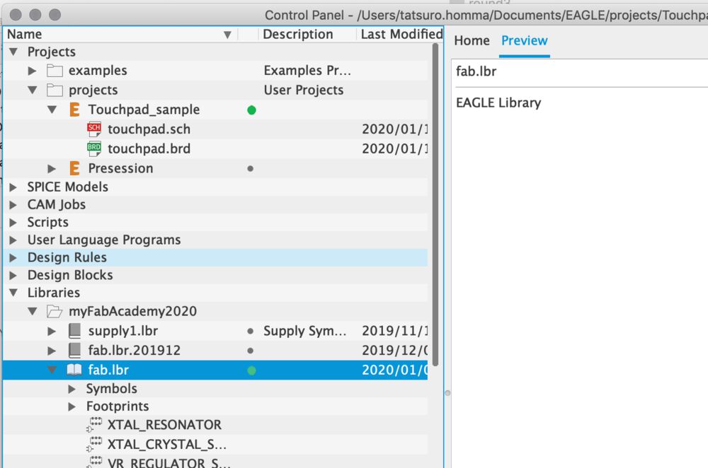
2) Extract archive and open "fab.lbr" from control panel in EAGLE.
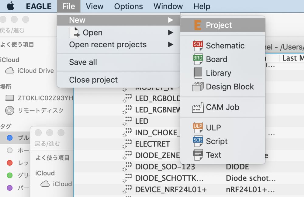
3) Create project (project name: echo1614)
File > New > Project
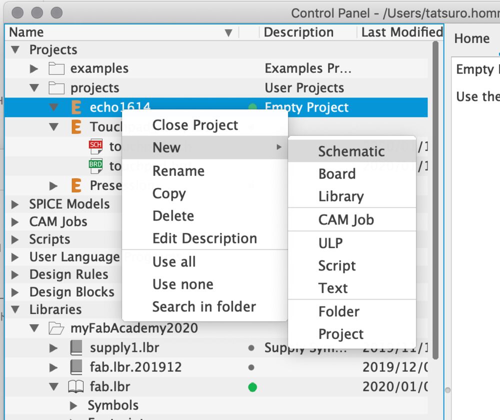
4) At project, create schematic.
(Project) New > Schematic
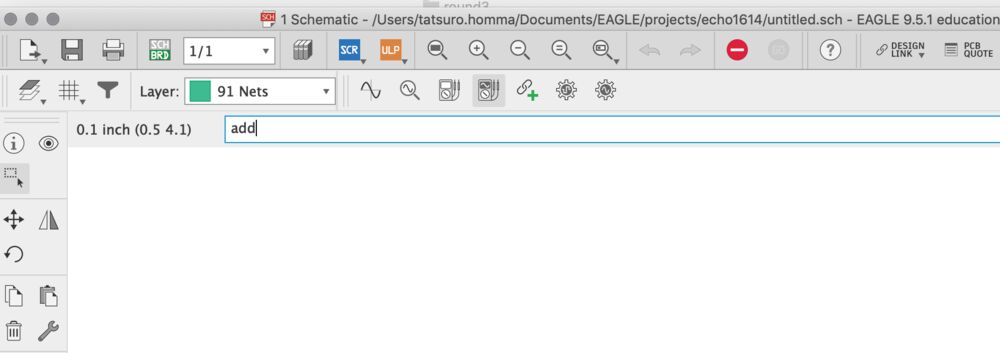
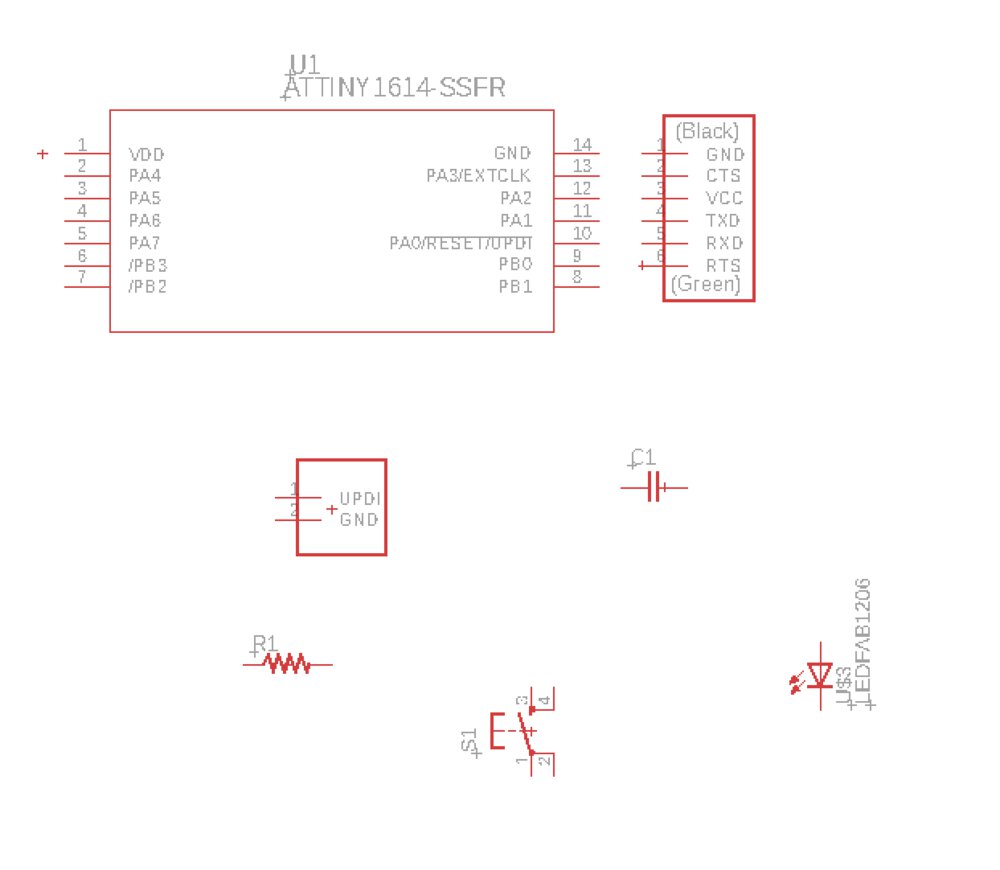
5) Open new schematic
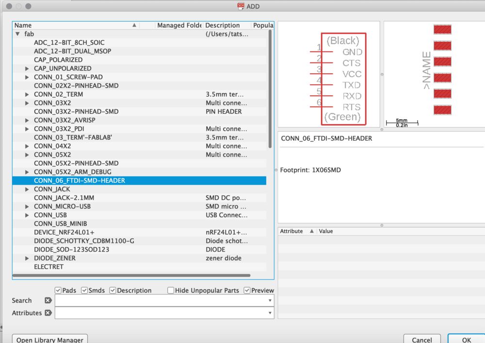
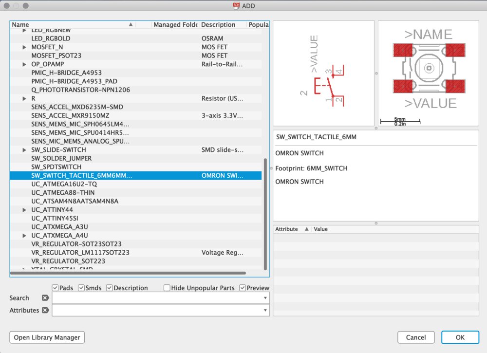
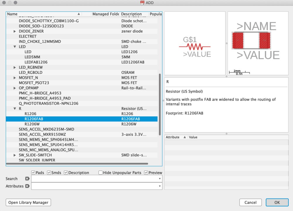
6) select component from library.
Example: Header pin (1x6pin for FTDI) - "CONN_06_FTDI_SMD_HEADER"
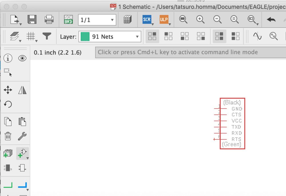
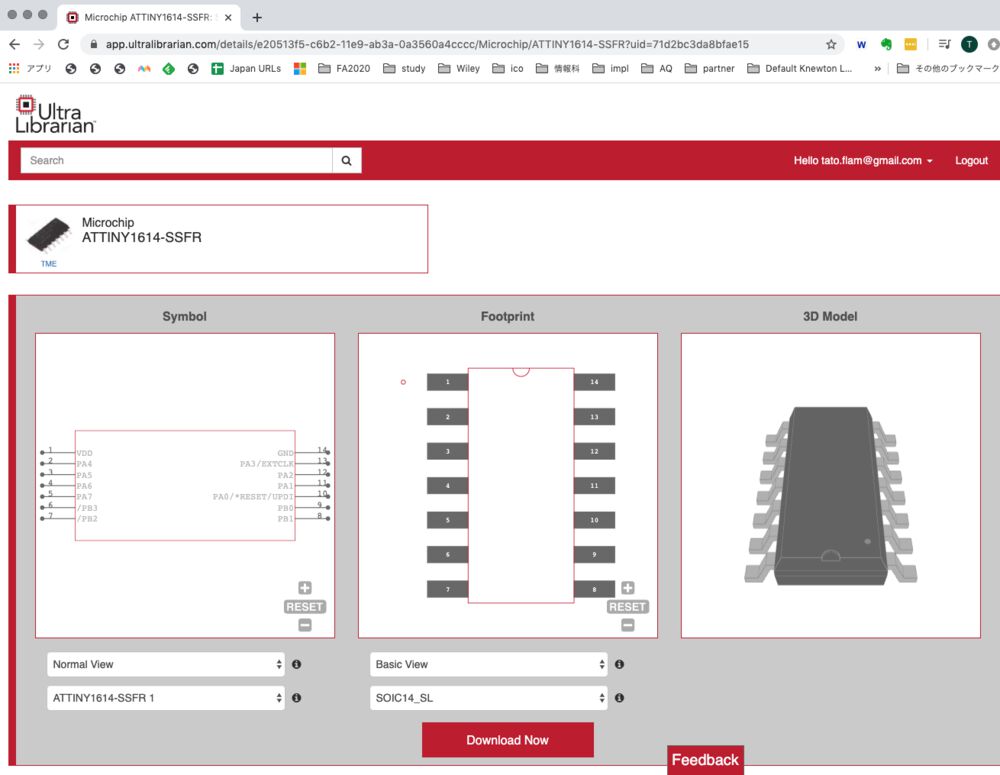
7) Open component in schematic view.
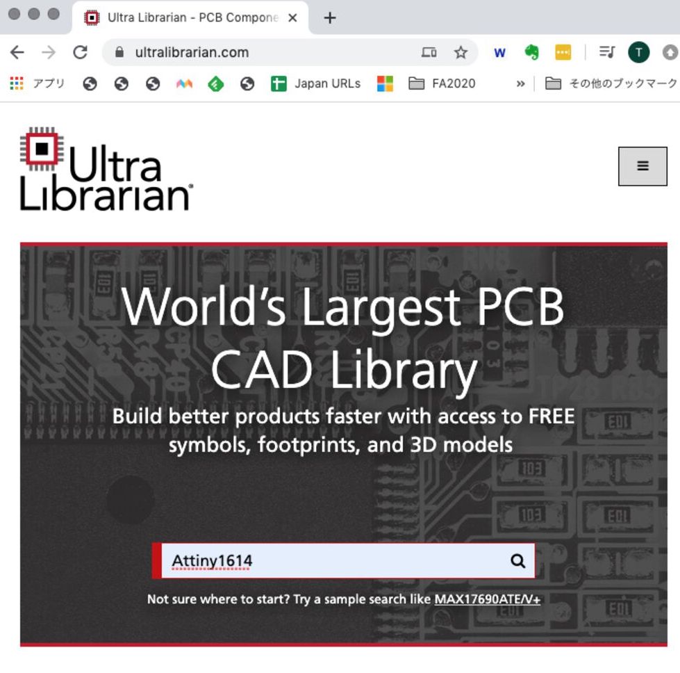
8) If you cannot find component at library, you can look for it at Ultra Librarian
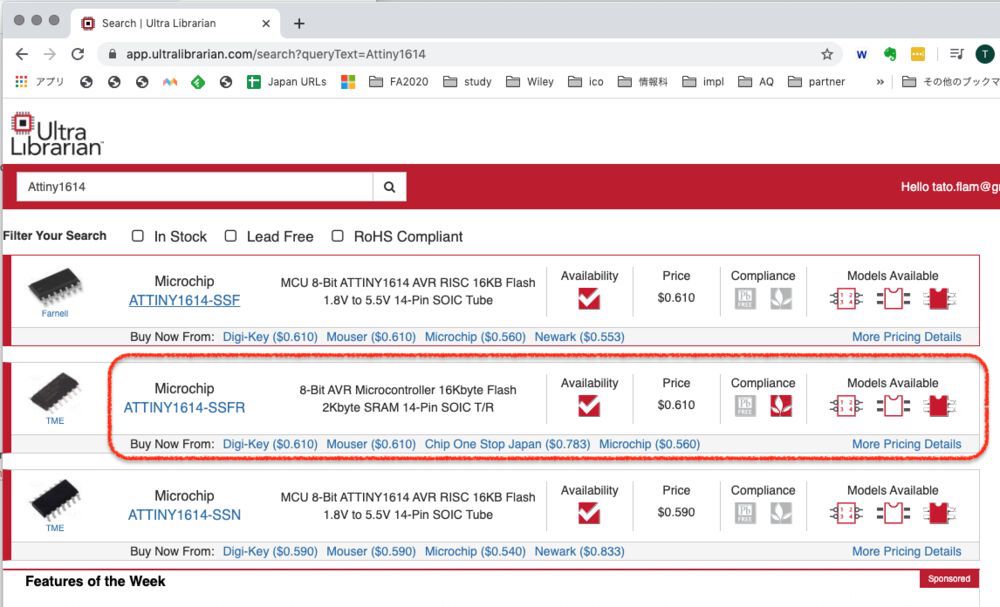
9) Find what is at your inventory.
10) Find what is at your inventory.
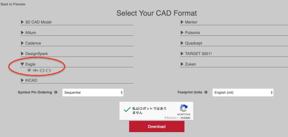
11) Check "EAGLE" and download it.
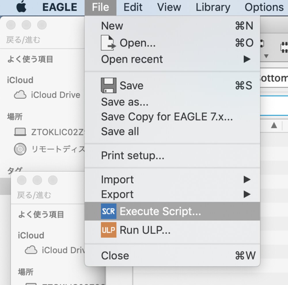
12) downloaded ".scr" file cannot be imported directly.
File > "Execute Script", then you can open the ".scr" file and import it into the library.
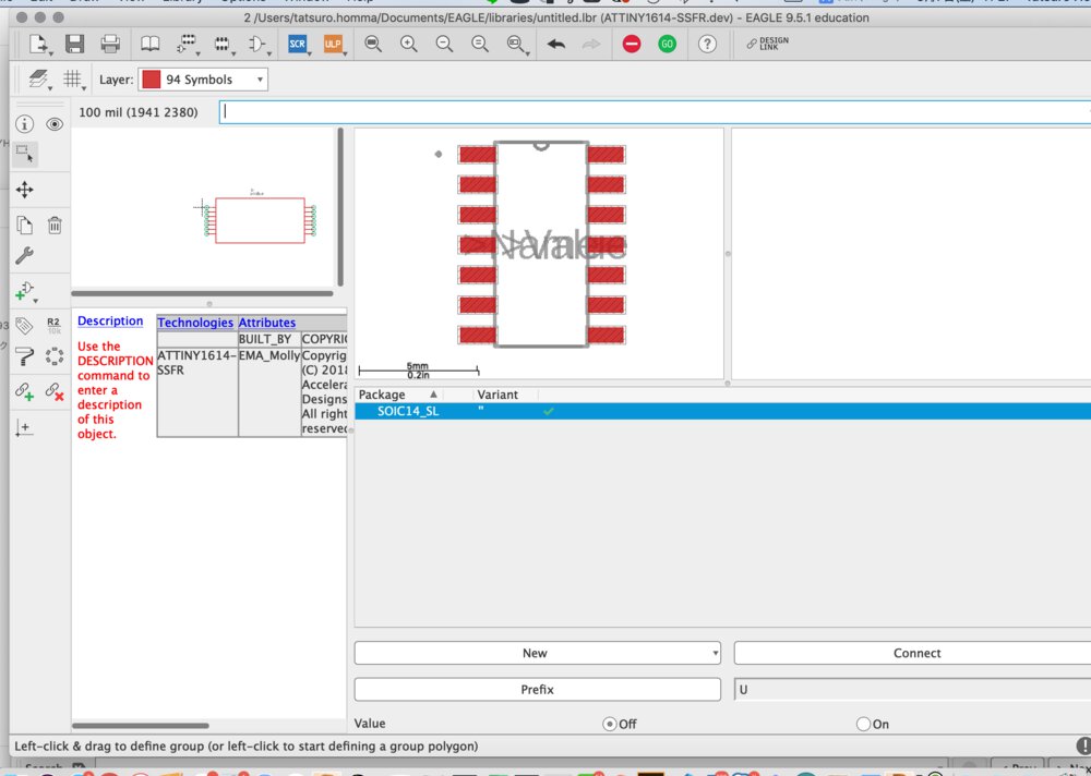
Here is what I imported.
BOM
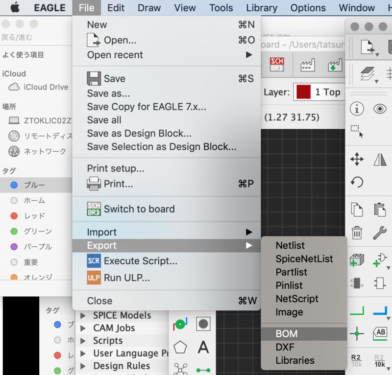
After download component, you can export "BOM(Bill of Material)" from EAGLE.
BOM of my echo board: week06_echoboard1614_BOM.html .
| Part | Value | Device | Package | Description | BUILT_BY | COPYRIGHT | MANUFACTURER_PART_NUMBER | VENDOR |
| C1 | 1uF | CAP_UNPOLARIZEDFAB | C1206FAB | |||||
| R1 | 1k | R1206FAB | R1206FAB | Resistor (US Symbol) | ||||
| R2 | 10k | R1206FAB | R1206FAB | Resistor (US Symbol) | ||||
| S1 | SW_SWITCH_TACTILE_6MM6MM_SWITCH | 6MM_SWITCH | OMRON SWITCH | |||||
| U$1 | CONN_06_FTDI-SMD-HEADER | CONN_06_FTDI-SMD-HEADER | 1X06SMD | |||||
| U$2 | CONN_02_UPDI-SMD-HEADERCONN_02_UPDI-SMD-HEADER | CONN_02_UPDI-SMD-HEADERCONN_02_UPDI-SMD-HEADER | 1X02SMD | |||||
| U$3 | LEDFAB1206 | LEDFAB1206 | LED1206FAB | LED | ||||
| U1 | ATTINY1614-SSFR | ATTINY1614-SSFR | SOIC14_SL | EMA_Molly | Copyright (C) 2018 Accelerated Designs. All rights reserved | ATTINY1614-SSFR | Microchip |
Wiring
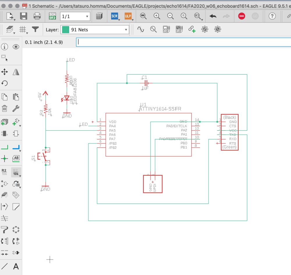
Then I wired the schematics. I used some commands like:
- move: move the component
- rotate: rotate the component
- net: connect between components
- name: add name of components
- value: add value of components (ex. 1k, 10K (Ω for resister))
I follow the board pattern of sample echo board. Actually, it's not usual case to write connection under the parts (by Tamiya-san's review)
For stabling the voltage of tact switch when the switch is off, I added pull up resister to the side of S3/S4 of switch.
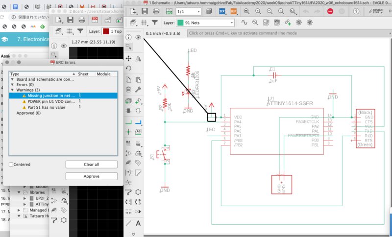
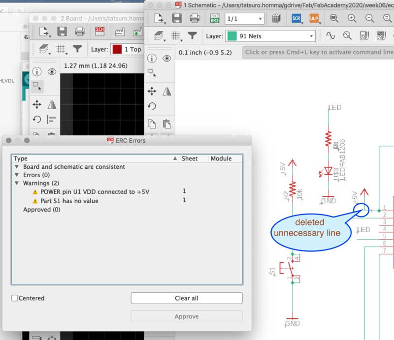
ERC
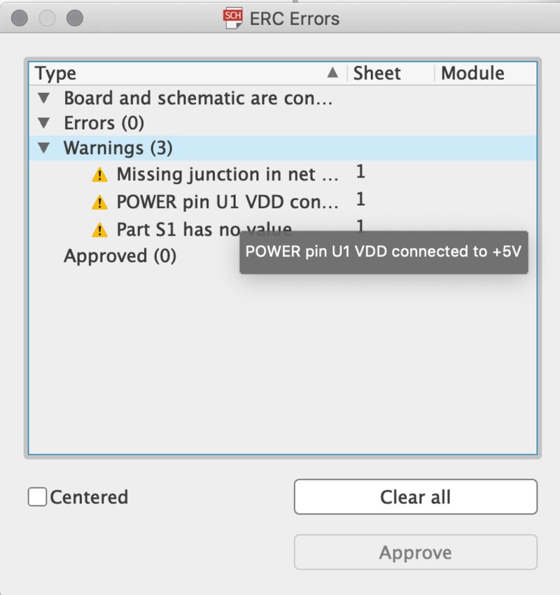
After wiring is completed, we can check ERC(Electrical Rule Check). We can check if the circuit is correct electrically.
At schematics, "Tools" > "ERC"
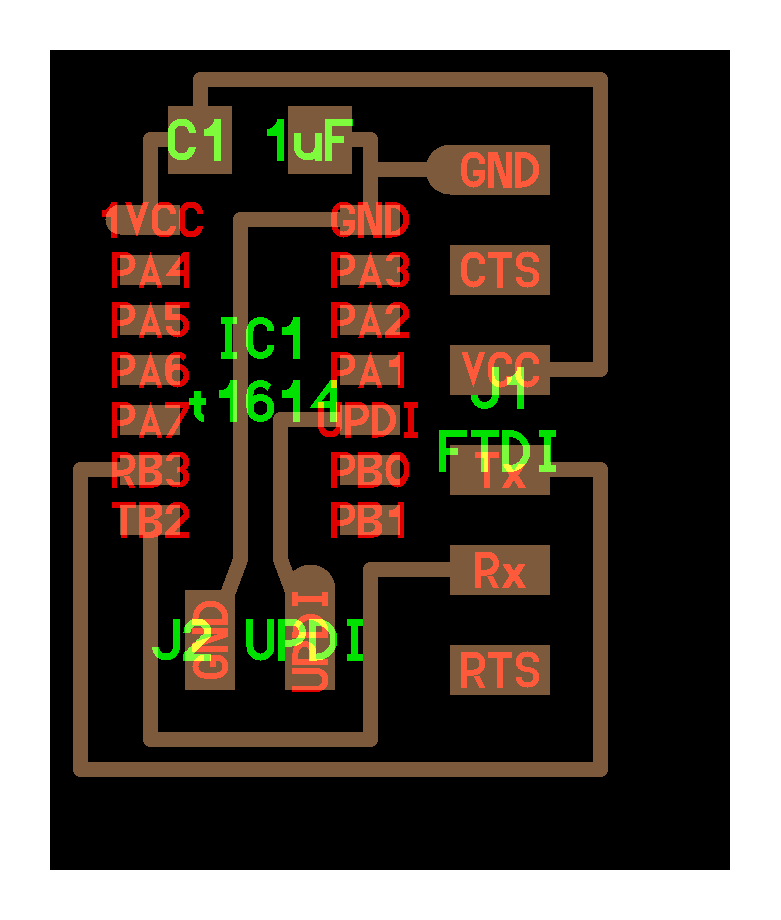
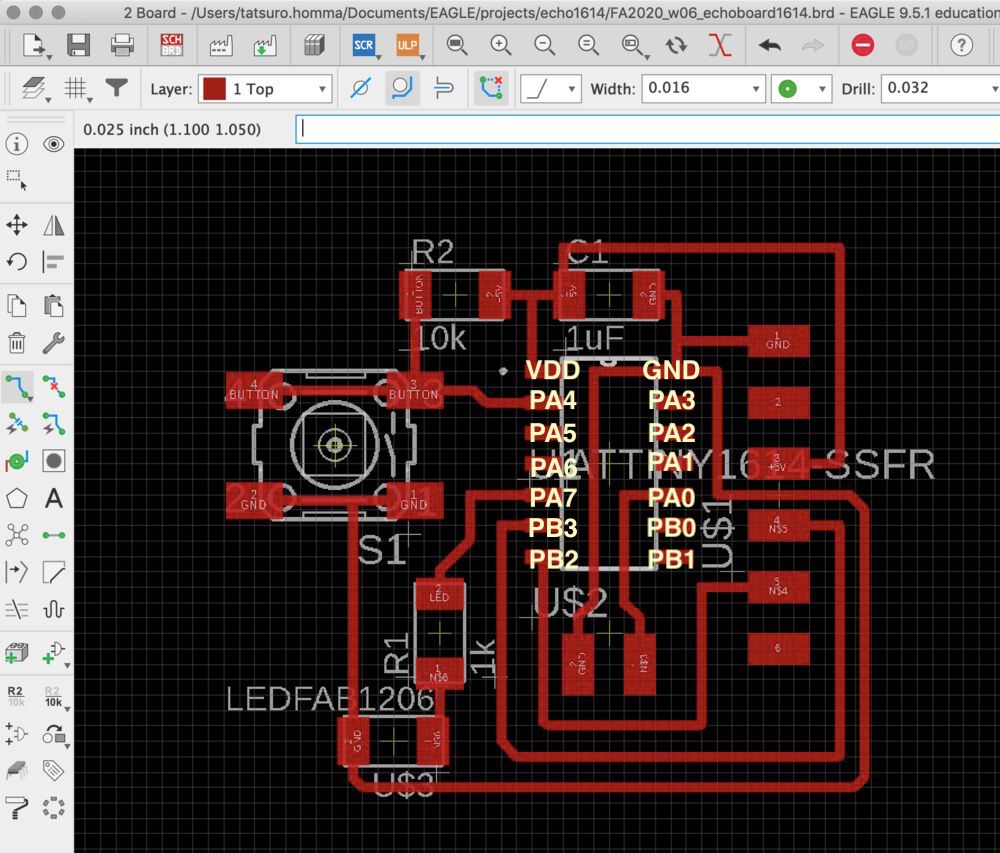
Board Pattern Design
Grid Settings
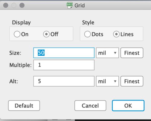
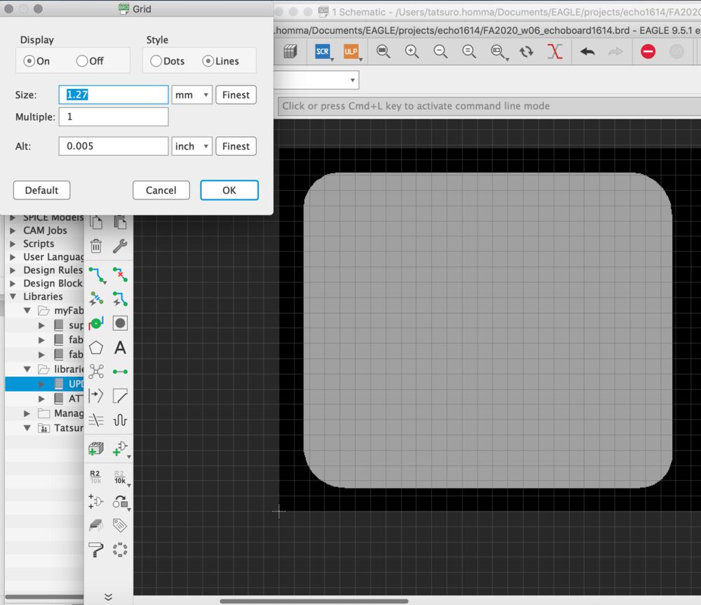
Set grid to 50 mil. Display "on" shows grid to board pattern pad.
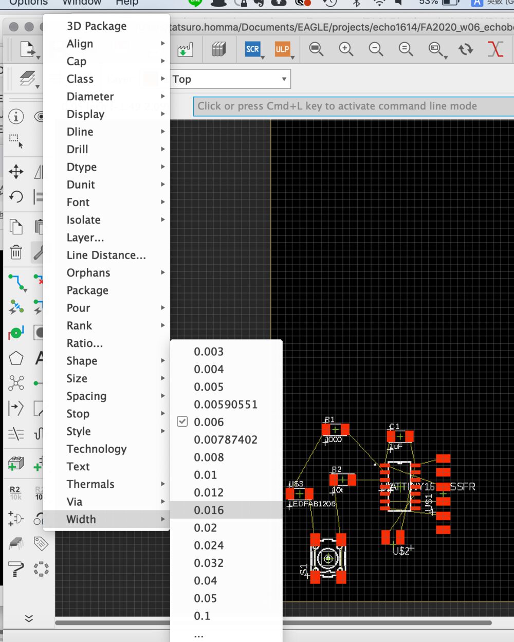
"Change" > "Width" > "0.016" (0.016 mil inch = 0.40 mm)
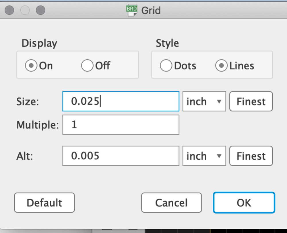
It's good to change the grid to 0.025 inch for drawing detail path.
Ratsnest
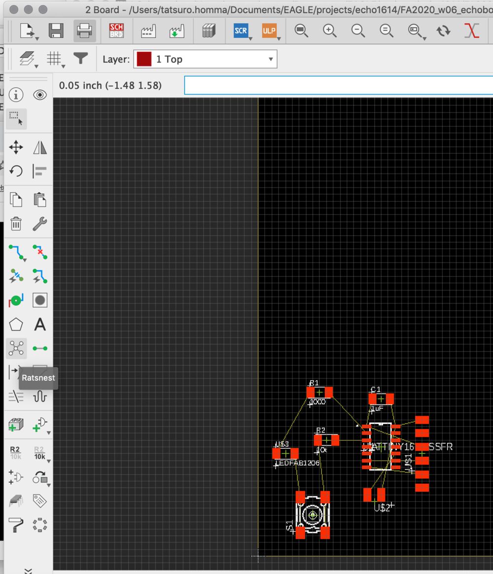
At the Board Pattern view, you can run "Ratsnest" for checking unconnected line.
If anything happens after running ratenest, it's OK.
Design Rule Settings
I imported DRC(Fabcity Design Rules) to local EAGLE.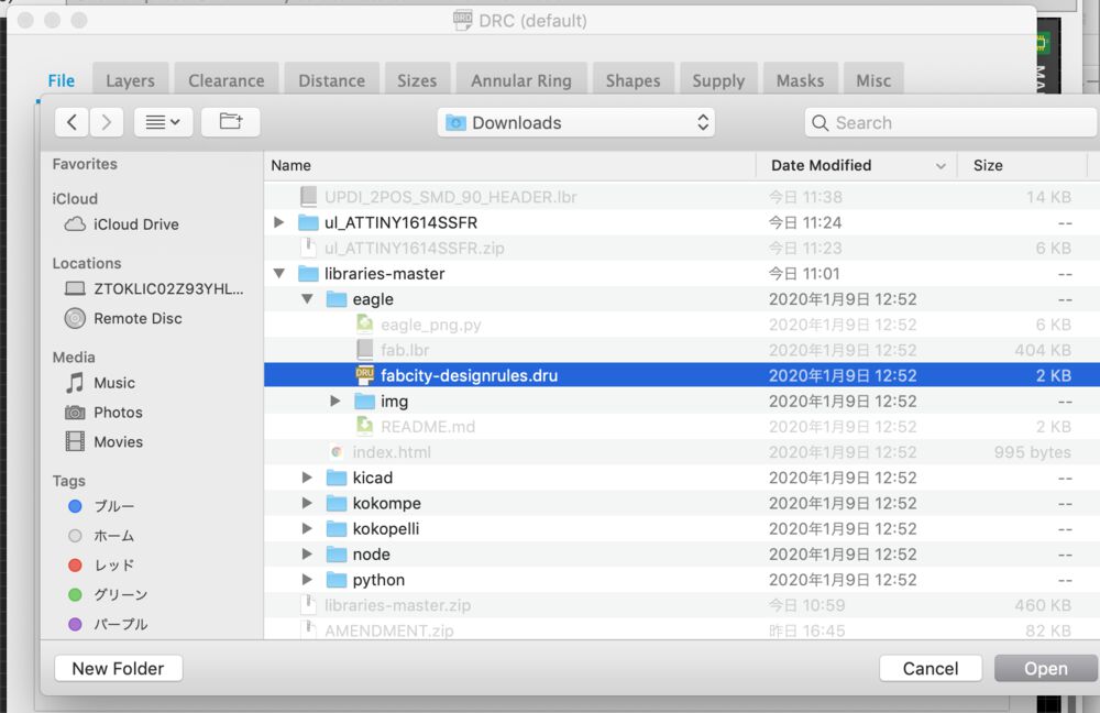
At "Tool" > "DRC" > (File)Tab and "Load", load design rule file From downloaded library,
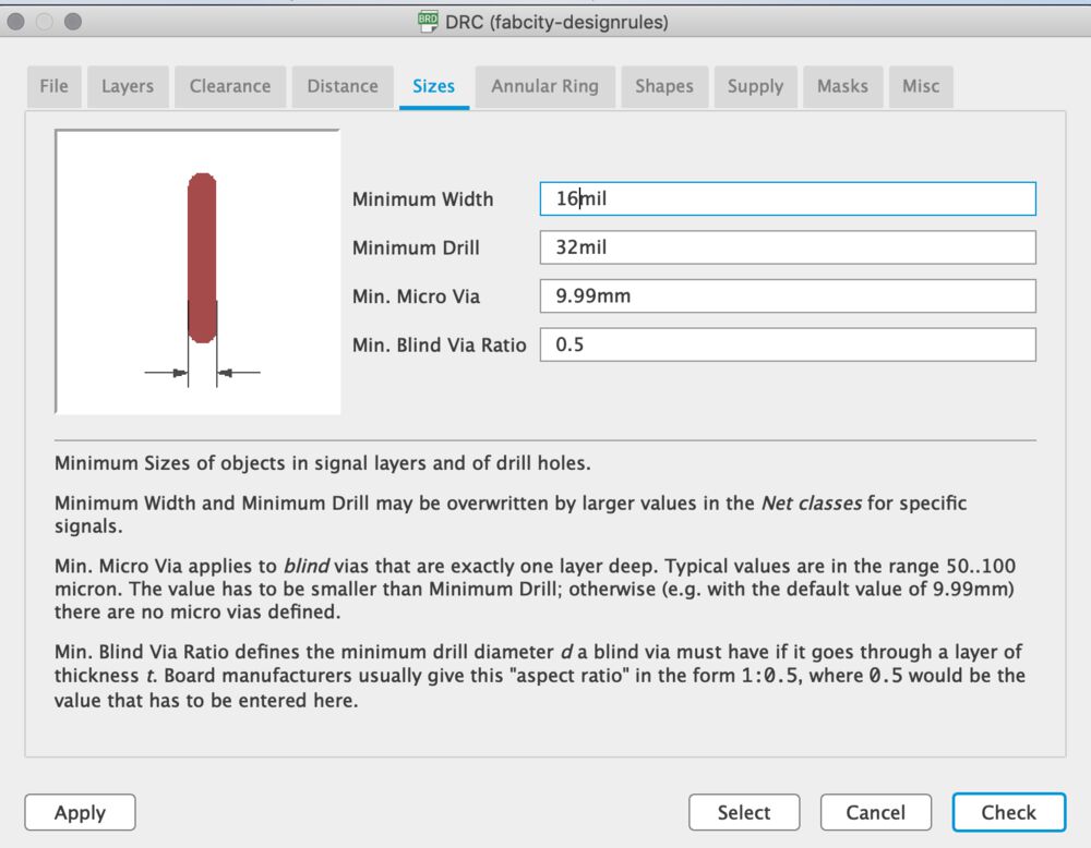
Change minimum width of drill to 16mil(0.40mm) from 25 mil.
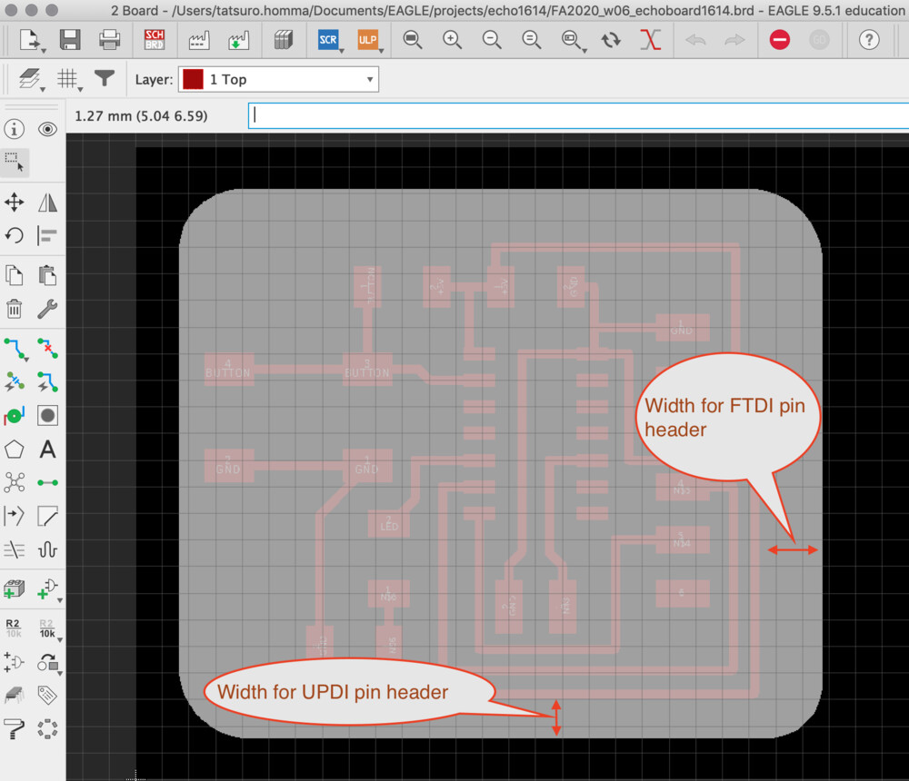
Make Board Pattern and checked design rules
Put the "SCHBRD(switch to Board) button and draw the board pattern.
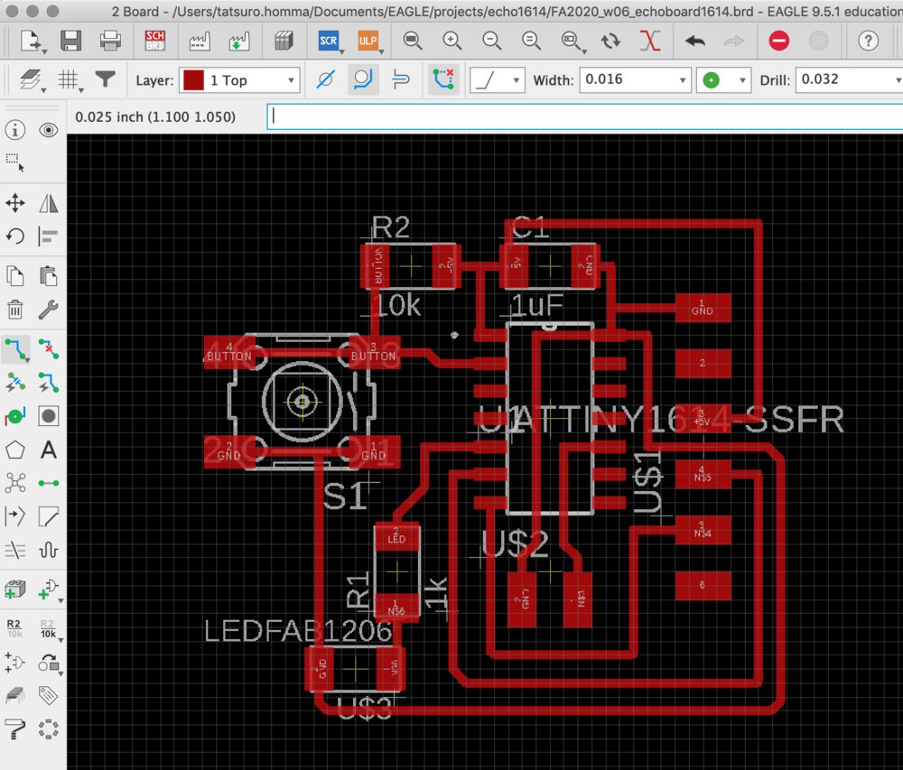
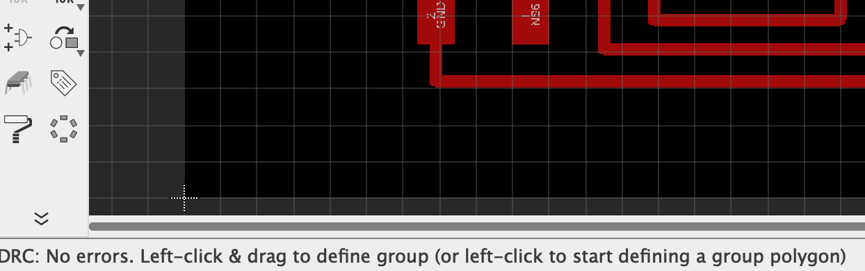
If DRC("Tool">"DRC") reports error, you need to correct it. I checked warning and refine the path.
Sometime, you need to write path from the center point of reg. Or you need to switch to schematic for putting name for component
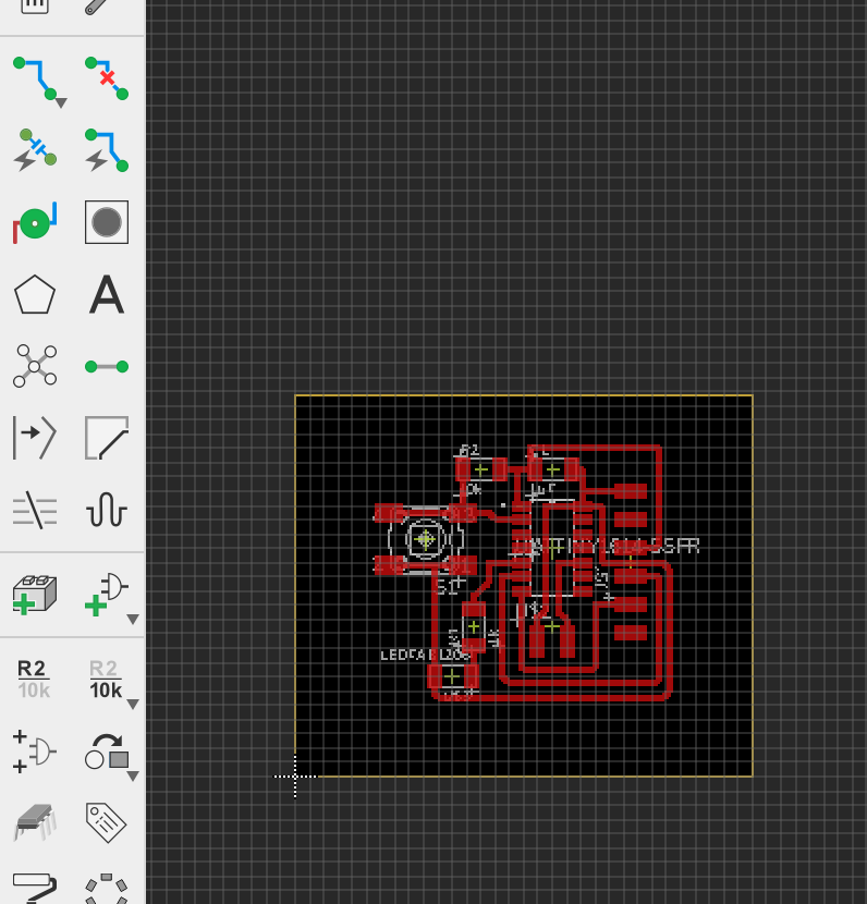
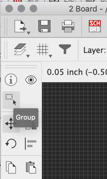
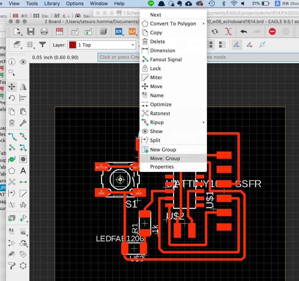
After completing to write board pattern, make the every traces as a group and move it to the cutting area.
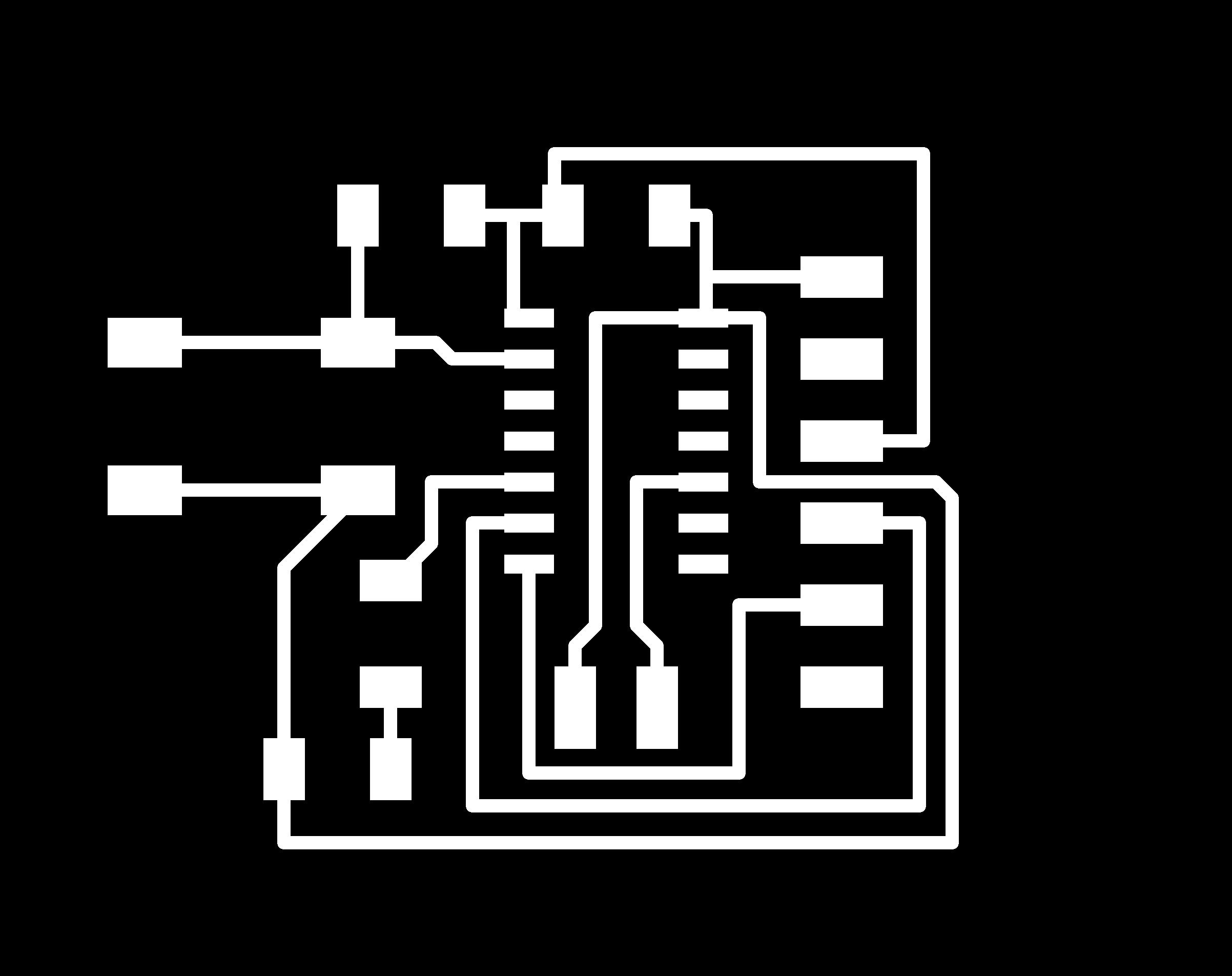
Outline
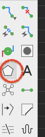
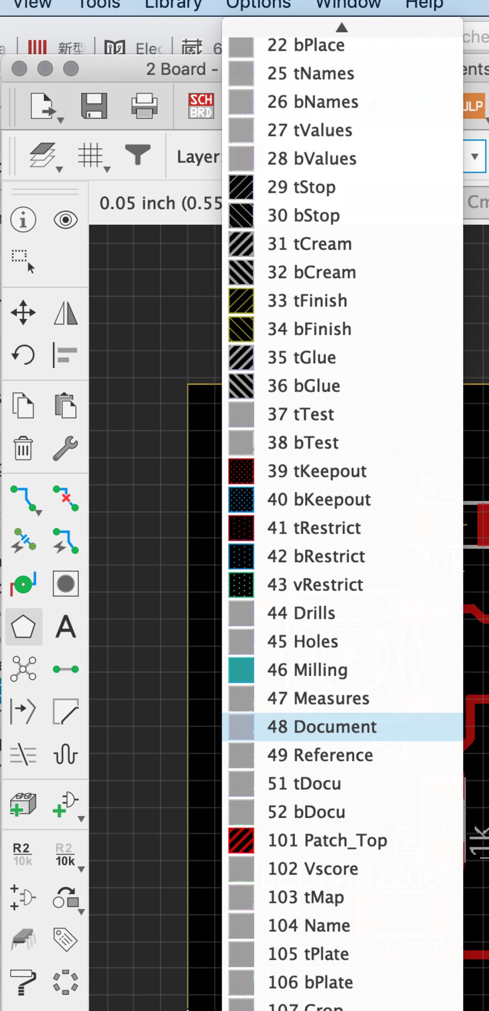
1) Checked polygon and select the layer of "48: Document"
2) Created outline.
Rounded corner is good not for hurting the hand.
3) Checked outline.
Firstly, I had narrow width between edge and trace area. However, too small length from edge will bring un expected electrical error or physical error in adapter connection.
I calculated
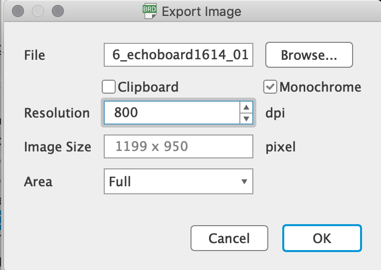
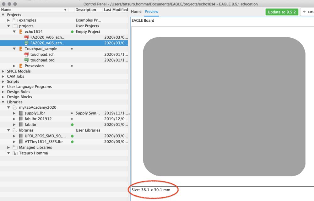
3) Exported png file to local storage. Check the dpi=800 and the physical length (38.1mm x 30.1mm)
Sometime, the CAM tools like mods or Fabmodule cannot load the same resolution of image file and the milled board gets bigger. It's good for us to check the size of image and re-check it at the CAM tool again.
The files exported are here

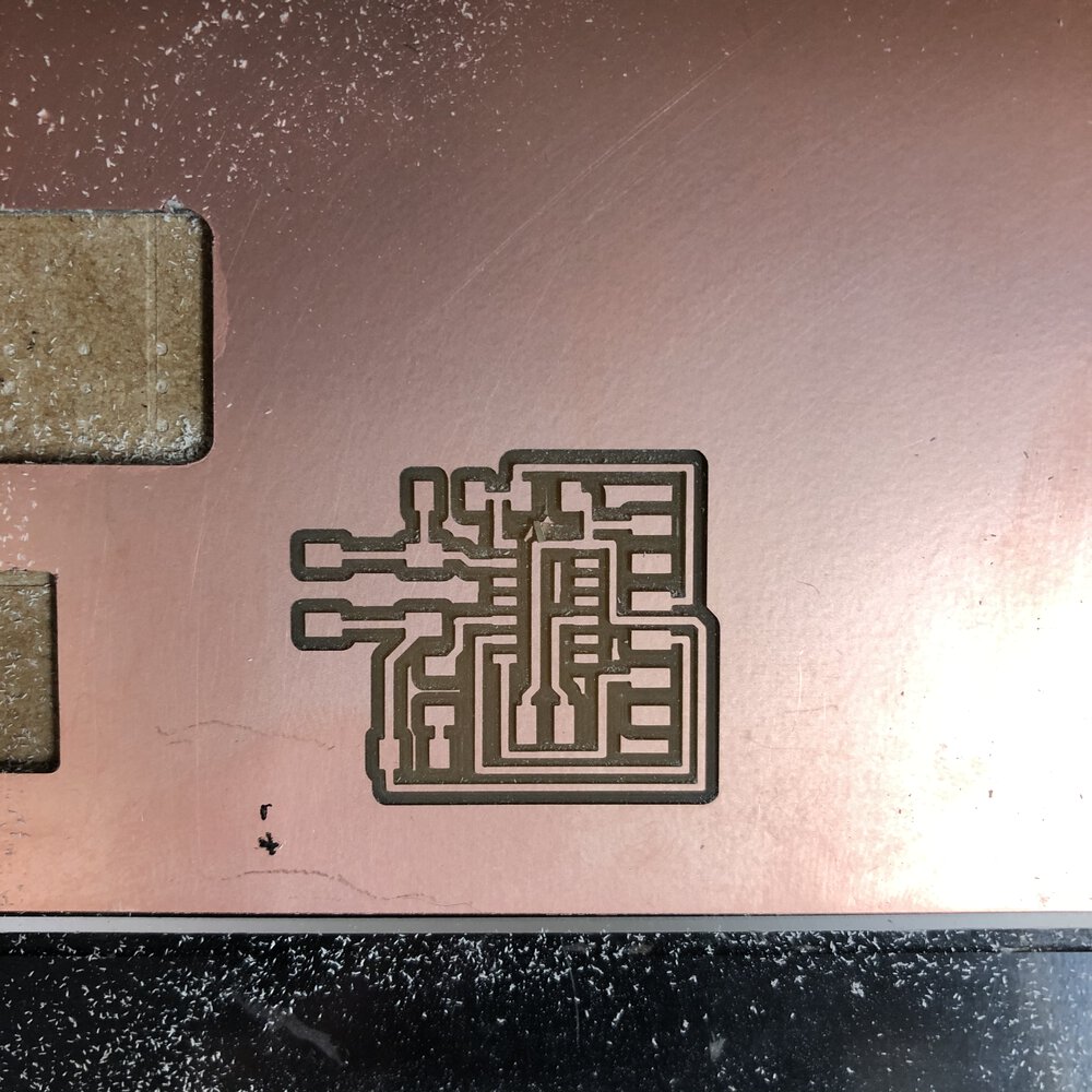
Milling
Then I milled the board by Roland MDX-15
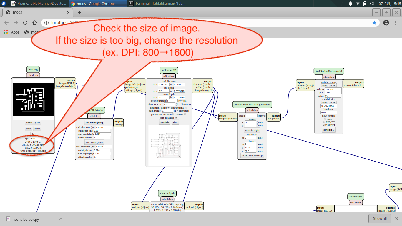
load "w06_echo1614_top.png" into mods
Check the size of image. If the file is too big, change the resolution of image (in my case, changing the DPI from 800 to 1600 resolved this issue)
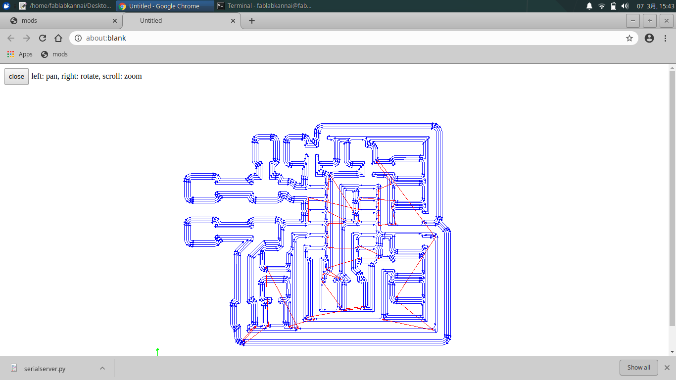
traced path with 1/64 inches endmil.
- Tool diameter: 0.39mm
- Cut depth: 0.2mm
- max depth: 0.2mm
- offset number: 4
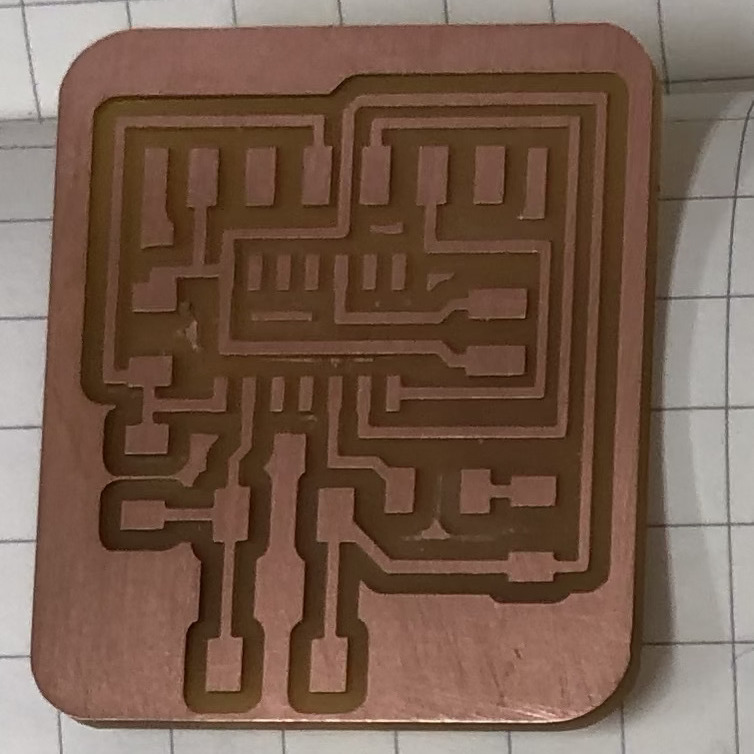
Checked if the cut path calculated by mods run through correctly and there is no short (connected part unintentionally).
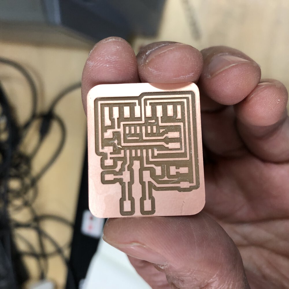
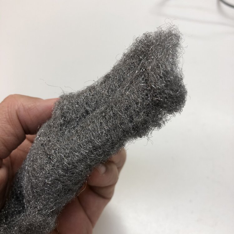
clean the surface of the copper with steel wool.
Purpose of using steel wool is deburring and copper oxide off for better soldering. Also, washing your finger oil out from board is another important proses.
Soldering
Then I got parts from Kannai Fablab Inventory, soldered them and tested the assembled board.
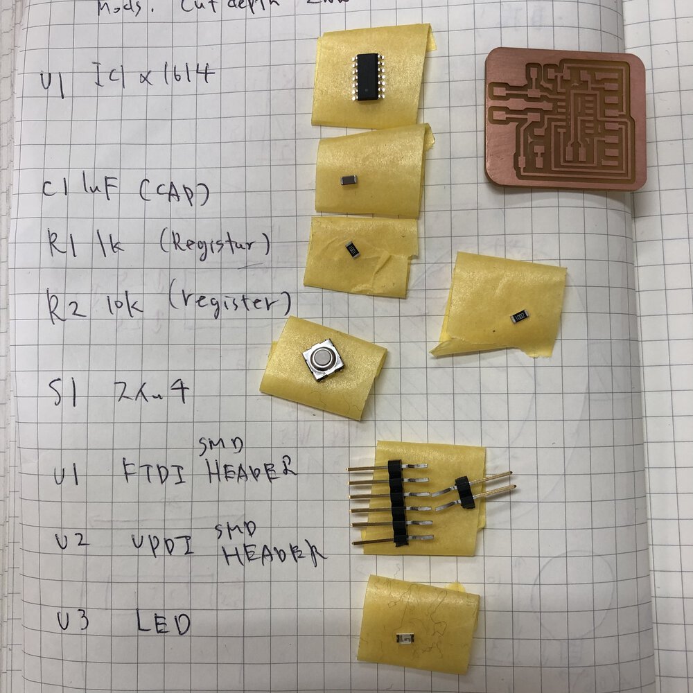
Materials are from Kannai inventory
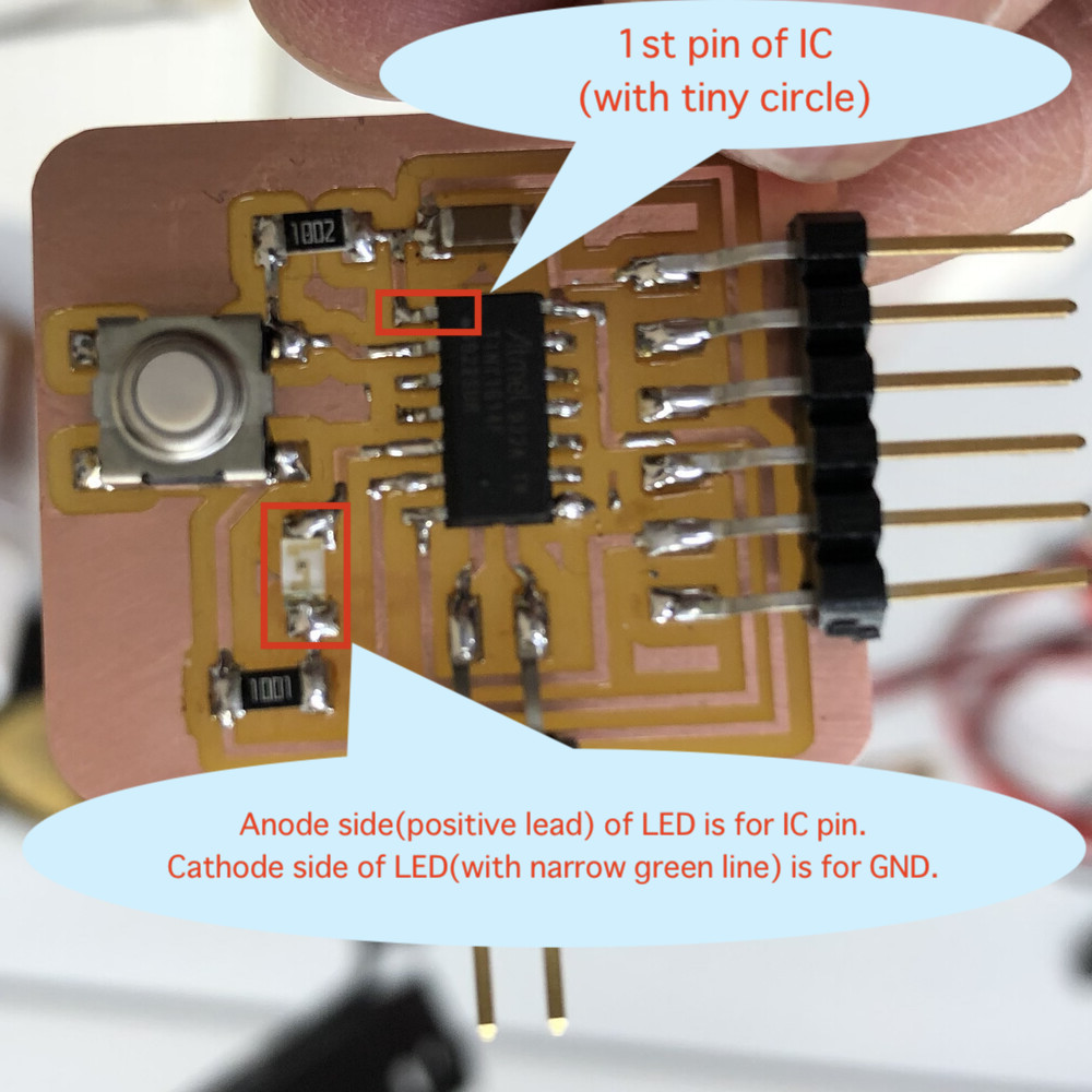
IC and LED has polarity.
1st pin of IC(VDD) is marked on the surface of ATtiny1614.
Anode side(positive lead) of LED is for IC pin. Cathode side of LED(with narrow green line) is for GND.
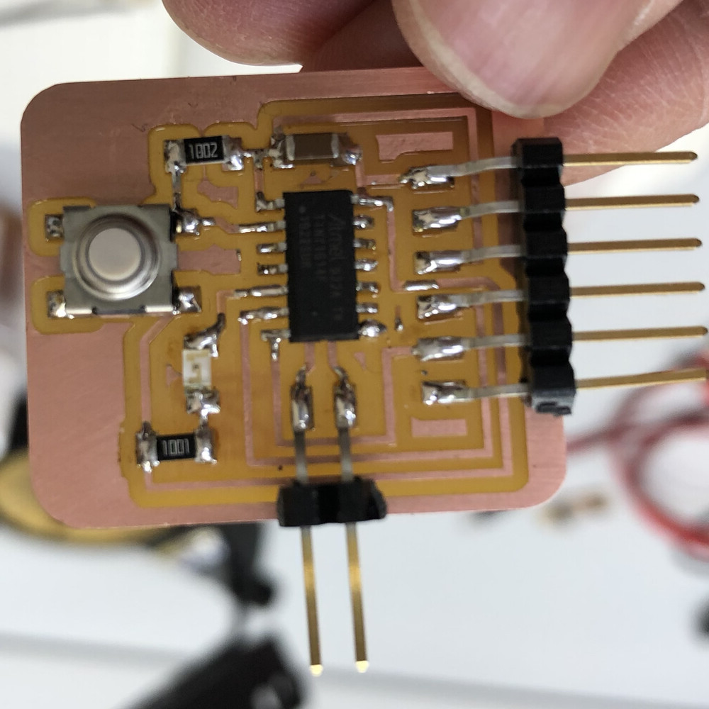
Assembled.
Actually, the assembled order of LED and 1K resister is different from the board design.Though the LED light turned on in both cases of
-1)IC - LED - resister - GND or
-2)IC - resister - LED - GND,
2) is better for protecting LED from current.
I tested where the path should not be connected. Though it was difficult for me to test tiny parts covered by round solder, finally I could finish the test and completed to assemble my echo board!
Program and Test
I followed the instruction for in-system development(AVR 0,1-series) made by my instructor, Tamiya-san.
work flow is
- configure Arduino IDE for building program from .ino file
- configure board manager of Arduino IDE as ATtiny1614 micro controller program
- compile program
- install python libraries by pip3 and downloading
- write program
build .hex from .ino
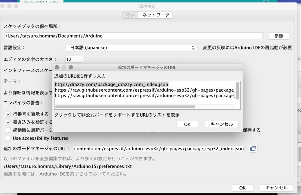
1) On Arudino IDE, Arduiono > preferences, I confirmed "Additional Board manager" has a URL of "http://drazzy.com/package_drazzy.com_index.json"
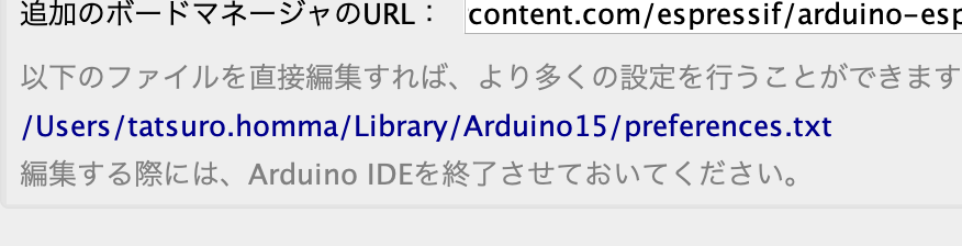
2) Checked the place of a setting file of Arduino(preference.txt). Then I close Arudino IDE and opened the preference.txt of Arduino.
Added the build path of build.path=/Users/tatsuro.homma/Arduino/build/to the "preference.txt. You need to shutdown the Arduino IDE. At mac environment, it's easier to open directly the text file specifying path like "/Users/${user}/Library/Arduino15/preferences.txt" by terminal editor like vim.
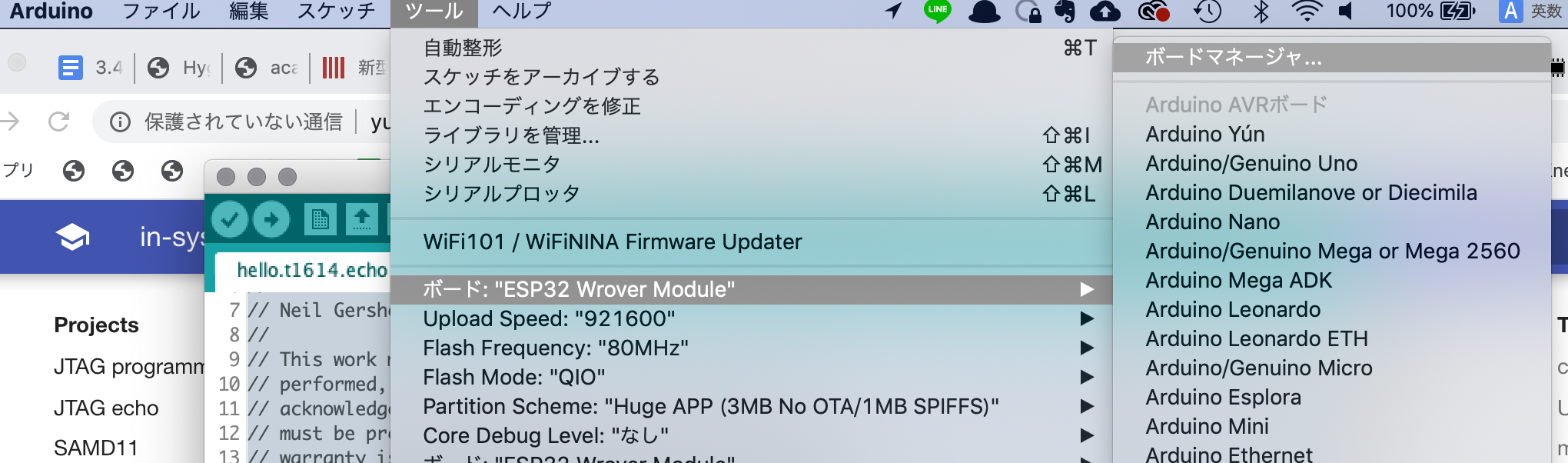
3) Re-open the Arudino IDE and "Tool" > "Board" > "Board Manager"
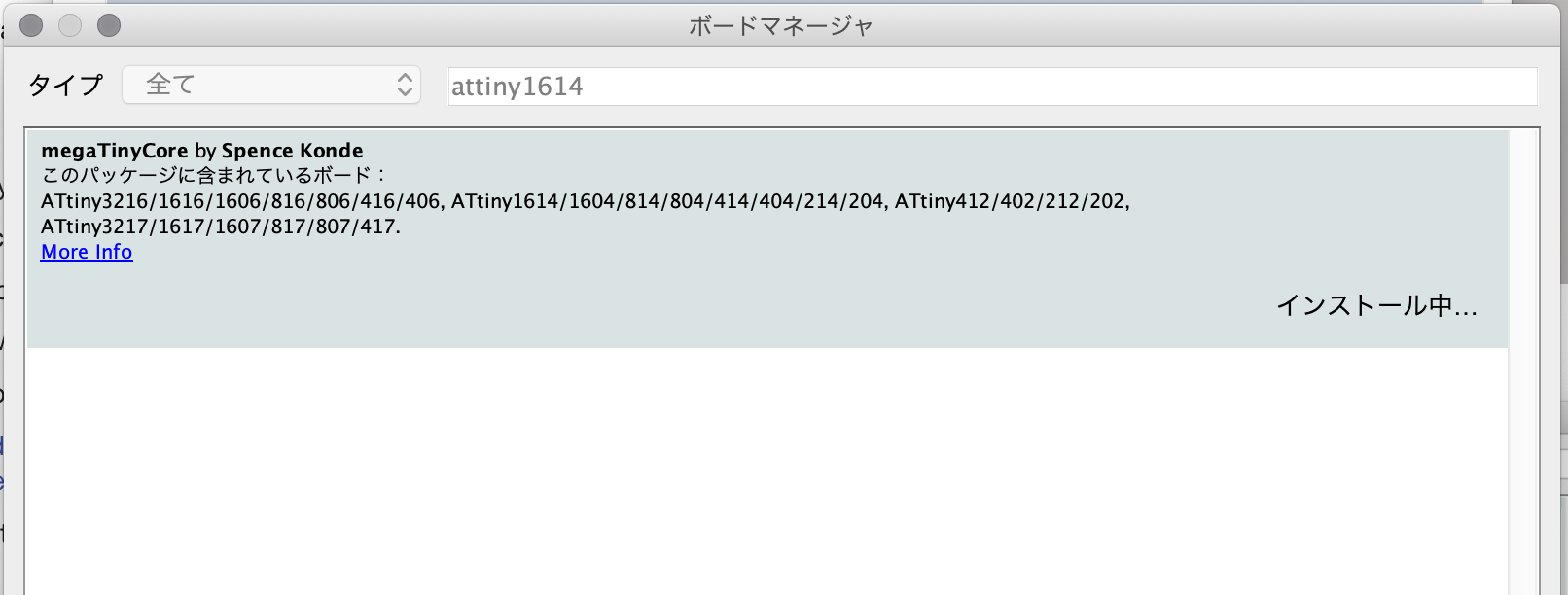
4) Search for "ATtiny1614" at the Board Manager.
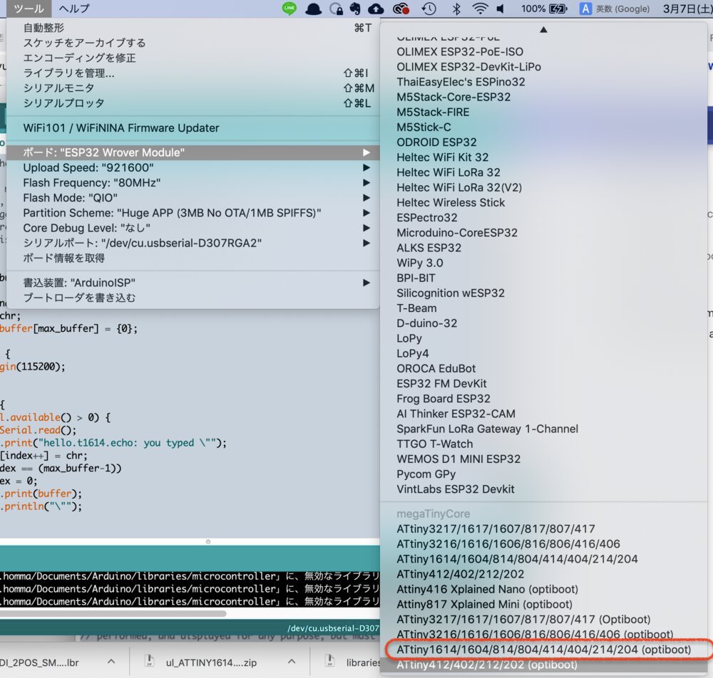
5) At Arduino IDE, "Tool" > "Board" and select the board manager that has a name of ATtiny1614.
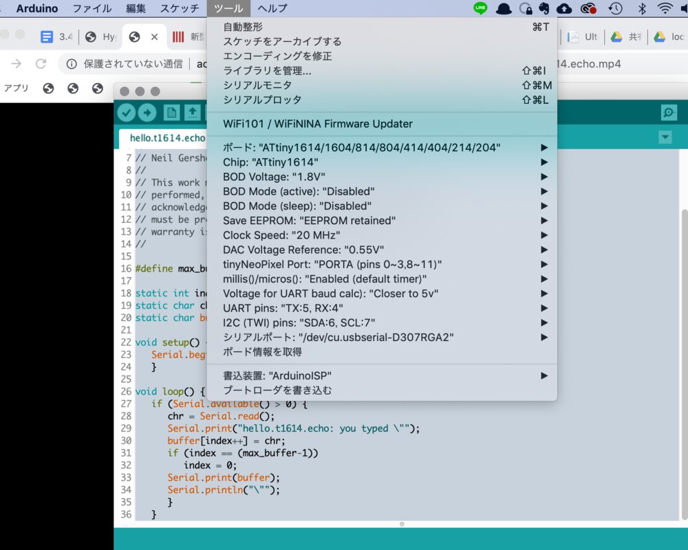
6) Check the settings at "Tool" in Arduino IDE.
- Board: "ATtiny1614/1604/814/...."
- BOD Voltage: 1.8V
- Clock Speed: 20MHz
- DAC Voltage Reference: 0.55V
- Voltage for UART Baud Calc: Closer to 5v
- UART Pins: TX:5, RX:4
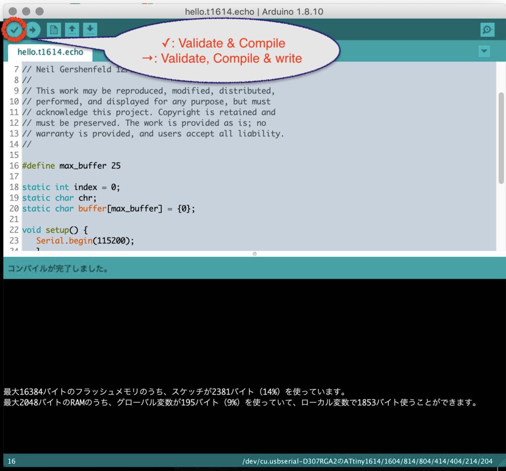
7) "✓" in Aruduino IDE (Validate & Compile)
Then you can get build file at the build path that is specified at 2) (build.path=/Users/tatsuro.homma/Arduino/build/).
you can open the file by Arduino IDE, however you cannot edit it. For editing it, you need to open it by the other text editor.
Write progarm from Linux
$ cd ~
$ pip3 install intelhex pylint pyserial
Also, downloaded pyupdi from github and extract zip file.
$ mkdir -p pyupdi
$ ce pyupdi
$ unzip -j pyupdi_master.zip
$ ls
pyupdi_master pyupdi_master.zip
Path of extracted pyupdi.py at xbuntu is: /home/fablabkannai/FA2020/pyupdi/pyupdi-master/pyupdi.py
Firstly, I tried to write my program from my Macbook Pro. However, I could not make the pip3environment at this point. This is because my macbook pro environment is configured for Python2 and repository of pip is referred to my company's pip repository. I came up with an idea to make the separated virtual environment for python3 library.
As I cannot save my time because of time constraints at the activity at Fablab, I left my mac and run $ pip3 install intelhex pylint pyserial and download pyupdi at the xbuntu laptop at Kannai. Afterward, I resolved this and successfully wrote my program from macbook pro (see below 13))
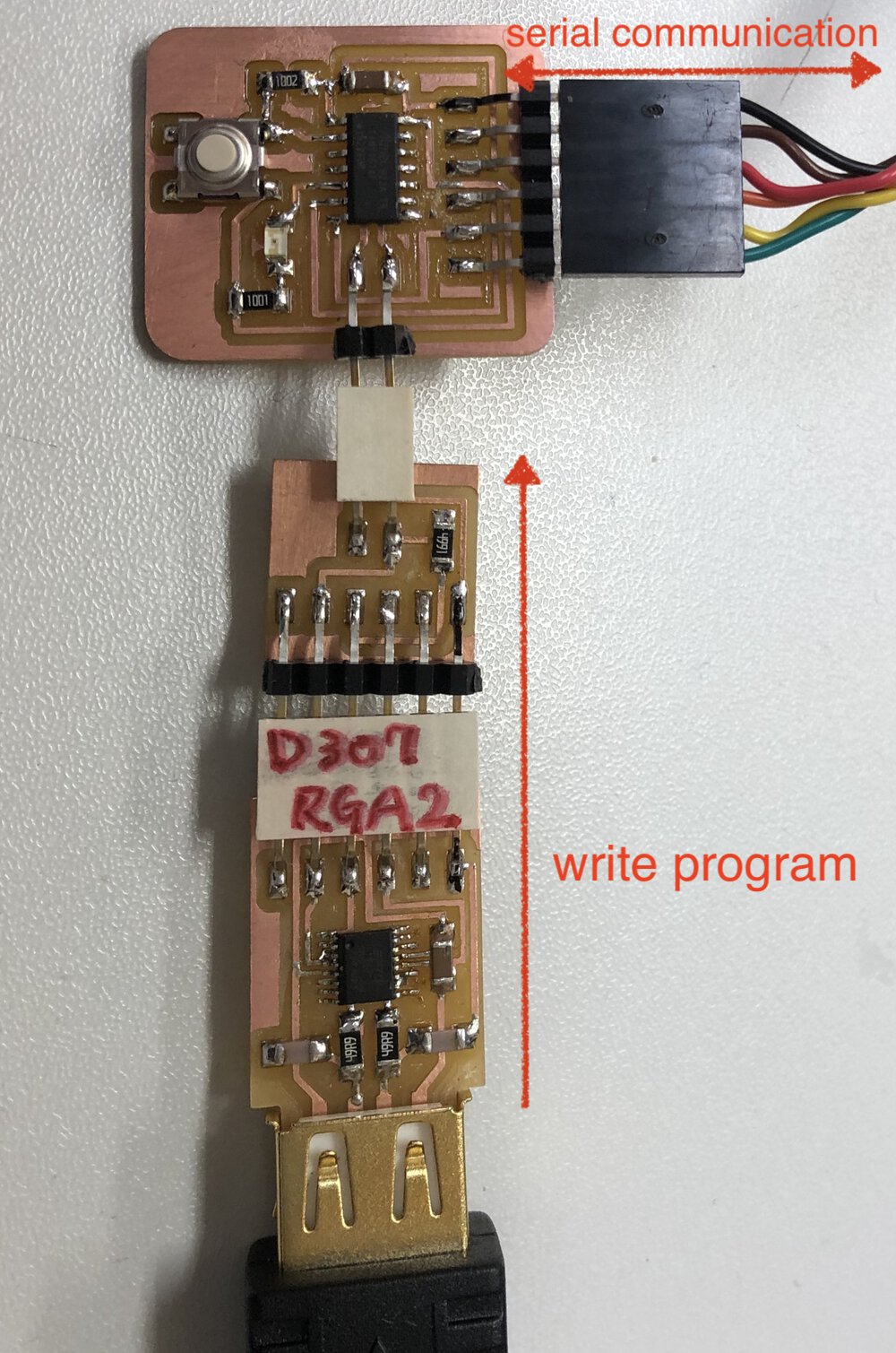
2) Connect and check the devices
xbuntu (USB Type A for serial communication)
|
USB-Serial converter cable (FTDI)
|
echo board (FTDI 1x6 pin)
echo program
echo board (UPDI 1x2 pin)
|
UPDI(1x2pin)-FTDI(1x6pin) board
|
FTDI(1x6pin)-USB board
|
USB TypeA(female)-USB TypeA(male)
|
xbuntu (USB Type A for programmer)
ttyUSB0
ttyUSB1
$ lsusb
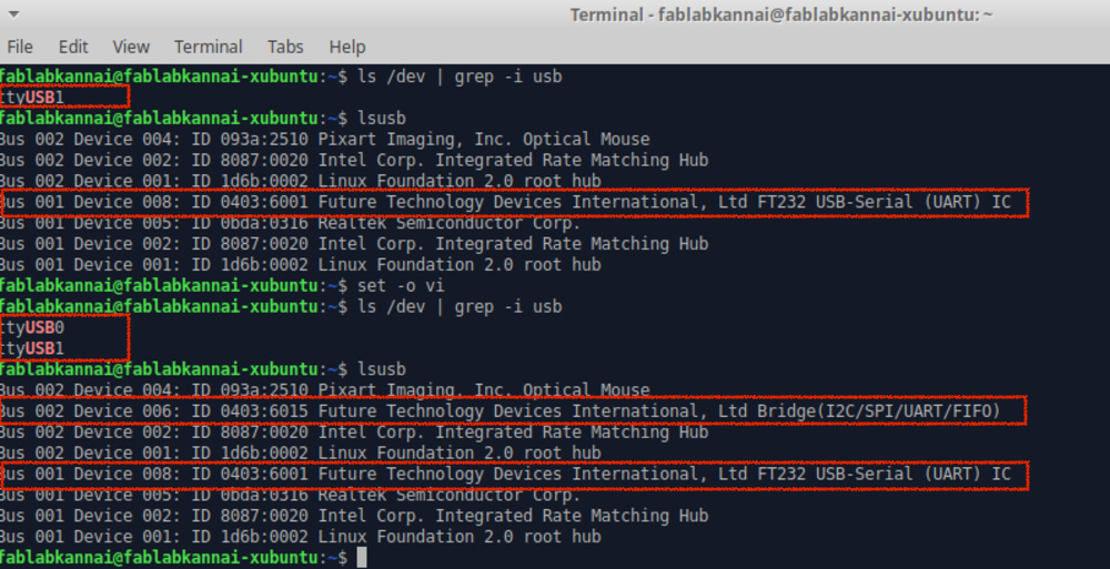
3) Check devices
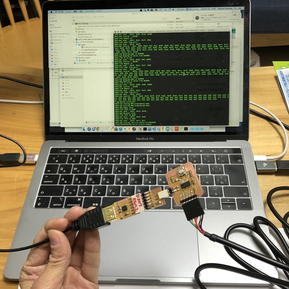
At first, I could find only the device for serial communiation and could not recognize the device for the programmer. After re-plug the USB type C-A adapter and change it for the cheap one (that has track record at Kannai), it worked!
It looks to be important to chose a good adapter(unrelated to the price) that can hold the plug strongly.
$ ls
hello.t1614.echo.ino.hex
$ python3 /home/fablabkannai/FA2020/pyupdi/pyupdi-master/pyupdi.py -d tiny1614 -c /dev/ttyUSB0 -b 115200 -f hello.t1614.echo.ino.hex -v
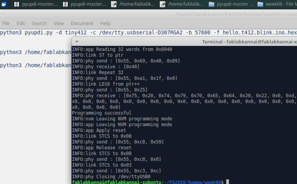
4) write program
Firstly, I could not write program. The pyupdi.py raise an error with messages like "Incorrect echo data", "Failed to chip erase using key" or "Failed to enter NVM programming mode" etc. However, after changing the USB adapter and re-plug the converters, it worked! So, in my case, it worth checking your adapter and connection status.
$ ls
hello.t1614.echo.ino.hex
$ python3 /home/fablabkannai/FA2020/pyupdi/pyupdi-master/pyupdi.py -d tiny1614 -c /dev/ttyUSB0 -b 115200 -f hello.t1614.echo.ino.hex -v
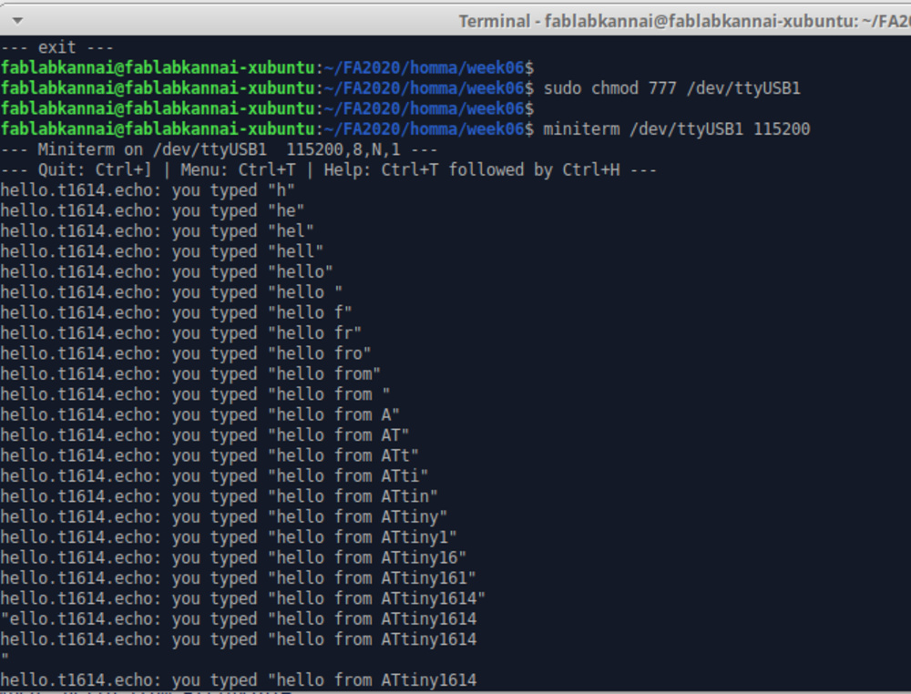
5) confirmed echo program
Before doing echo, I run sudo chmod 777 /dev/ttyUSB1 after specifying the USB port for serial and add authorization. In my case with linux, I needed to do this every time I re-plug the echo devices.
Then I run miniterm and check echo program successfully.
It looks that miniterm is contained by pySerial.
Write progarm from mac
1) (Mac) setup for macbook pro laptop of UPDI programmer and serial communication with ATtiny1614.
I wanted to have mac environment as that is my main machine.
/Users/tatsuro.homma/Arduino/build
confirm the python version on virtual environmebnt
system
* 3.7.0 (set by /Users/tatsuro.homma/Arduino/build/.python-version)
3.7.0/envs/scraping
confirm the python version 3 is set
Python 3.7.0
before installing via pip, upgrade pip version itself just in case
install required packages in dependeny of pyupdi. # As i could not pip3 install following packages, I directly installed pyserial and intlhex from github files.
$ pip3 install git+https://github.com/pyserial/pyserial.git
$ pip3 install git+https://github.com/python-intelhex/intelhex.git
I checked my python environment at my macbook pro laptop and worked on that. The solution is "construct python3 virtual envvrionment by pyenv and install package via pip3 in pyenv"
- setup python3 virtual environment using pyenv (terminal in/out memo1)
- install the required packages(pylint, intelhex and pyserial)(terminal in/out memo2)
/Users/tatsuro.homma/Arduino/build
install pyupdi via pip
3) (Mac) Install pyupdi enveiornment (via pip)
Firstly, I downloaded pyupdi.zip from github. However, downloading .zip requries additional work to check path and specifying explicitly in command or symbolic link.
it's cool to install pyupdi via pip (instead of downloading .zip and extract it) because pip envrironment can handle vesrions and dependencies. Also, you can write program via pyupdi at the environmenbt with direct command of pyupdi.py(without specifying the path of python3 /xx/x/xx/xx/pyupdi.py file by path or symbolic link etc.)
cu.usbserial-D307RGA2
cu.usbserial-FT9OZSKA
tty.usbserial-D307RGA2
tty.usbserial-FT9OZSKA
$ pyupdi.py -d tiny1614 -c /dev/tty.usbserial-D307RGA2 -b 57600 -f hello.t1614.echo.ino.hex
Programming successful
4) (Mac) program an echo program from mac
cu.usbserial-FT9OZSKA
tty.usbserial-FT9OZSKA
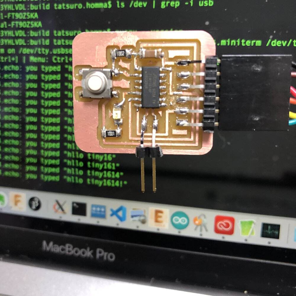
$ python -m serial.tools.miniterm /dev/tty.usbserial-FT9OZSKA 115200
--- Miniterm on /dev/tty.usbserial-FT9OZSKA 115200,8,N,1 ---
--- Quit: Ctrl+] | Menu: Ctrl+T | Help: Ctrl+T followed by Ctrl+H ---
hello.t1614.echo: you typed "h"
hello.t1614.echo: you typed "hl"
hello.t1614.echo: you typed "hll"
hello.t1614.echo: you typed "hllo"
hello.t1614.echo: you typed "hllo "
hello.t1614.echo: you typed "hllo t"
hello.t1614.echo: you typed "hllo ti"
hello.t1614.echo: you typed "hllo tin"
hello.t1614.echo: you typed "hllo tiny"
hello.t1614.echo: you typed "hllo tiny1"
hello.t1614.echo: you typed "hllo tiny16"
hello.t1614.echo: you typed "hllo tiny161"
hello.t1614.echo: you typed "hllo tiny1614"
hello.t1614.echo: you typed "hllo tiny1614!"
--- exit ---
5) (Mac) Completed to test echo program uccessfully
Lessons Learned
- When deciding the position of the parts of electronics design, it's good to imagine the physical board pattern and. Automatic patterning function seems to be useful but it might bring complex board pattern and electrically ineffective path lines.
- For easy soldering and embedding, check the margin between parts or edges.
- I challenged to make ATtiny1614 (AVR 0,1 series) based board. Though it was challenging, very good to know about strong compatibility in UPDI interface with fewer parts than ISP.
- It's very important to select "good" adapter or connector cable between interfaces.
- Python virtual environment is useful to construct separated environment for a program board.
- ICOVID-19 brought many works related in child care to me this week. I need more effective time management.
Files
- echo board(trace image): w06_echo1614_top.png
- echo board(outline image): w06_echo1614_outline.png (outline):
- schematic file: FA2020_w06_echoboard1614.sch
- board Pattern file: FA2020_w06_echoboard1614.brd
- echo program (built by Arduino IDE): hello.t1614.echo.ino.hex
References
- Attiny1614 datasheet
- Attiny1614 datasheet(Japanese)
- EAGLE
- Gitlab(pub) fab library
- pinhead-2.lbr
- instruction about pull up resister (Japanese:プルアップ抵抗について解説)
- the instruction for in-system development(AVR 0,1-series) by Tamiya-san
- pyupdi