Assignment
Week4: Electronics production
Assignment
- Group Assignment
- characterize the design rules for your PCB production process
- Individual Assignment
- make an in-circuit programmer by milling and stuffing the PCB, test it, then optionally try other PCB processes
- characterize the design rules for your PCB production process
- make an in-circuit programmer by milling and stuffing the PCB, test it, then optionally try other PCB processes
Table of content
My Work
I've learned about CNC and CAM at Fablab Kannai from my instructor Tamiya-san.
Group Assignment(Endmills, material, CNC, Test Cut and evaluation)
Link to group assignment page at Kannai lab
FabTinyISP(Brian)
For deciding which ISP to make in this week, I think about micro controllers to be used in my final project. As I will use Atmega328p for my final project (so far), I want to make ISP for AVR micro controller.
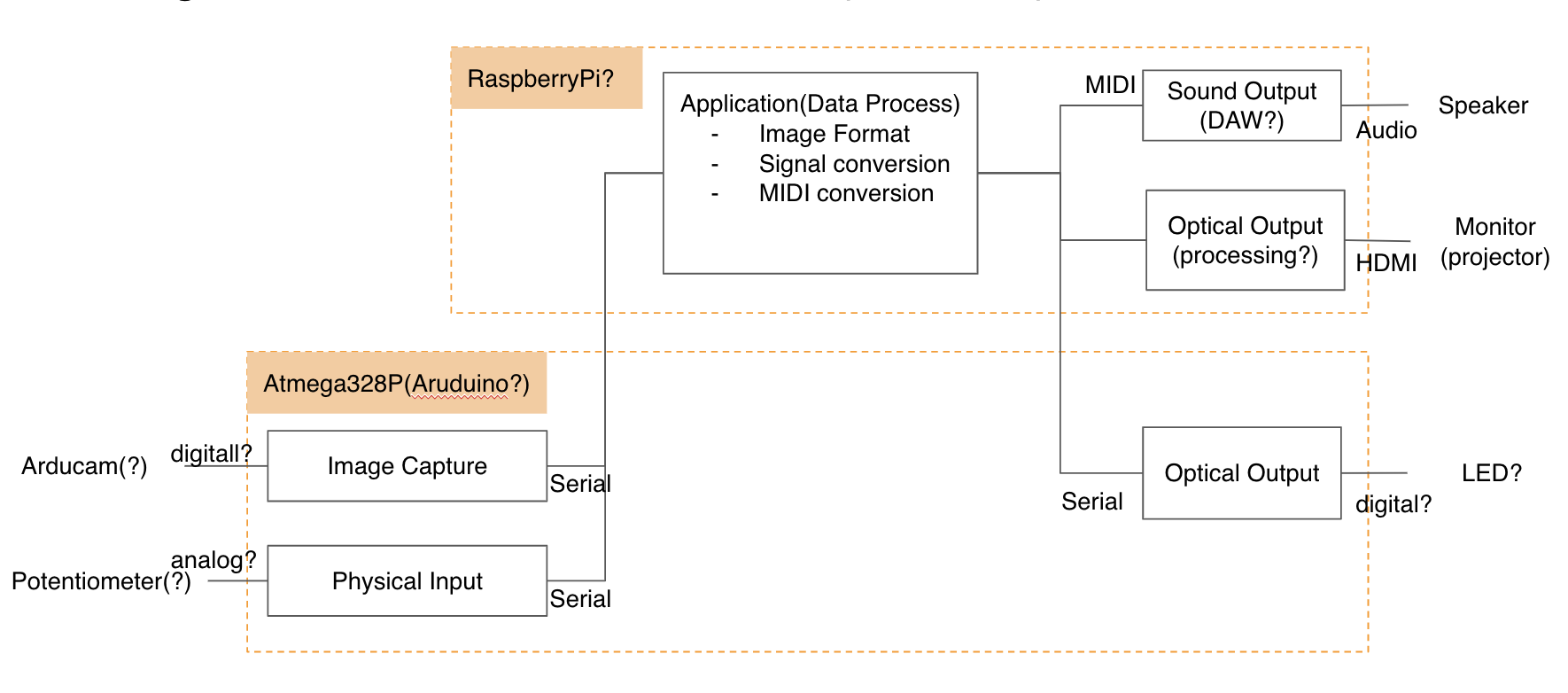
This diagram is initial architectural design overview of my final project from application and interfaces. This will be revised thorough FabAcademy 2020.
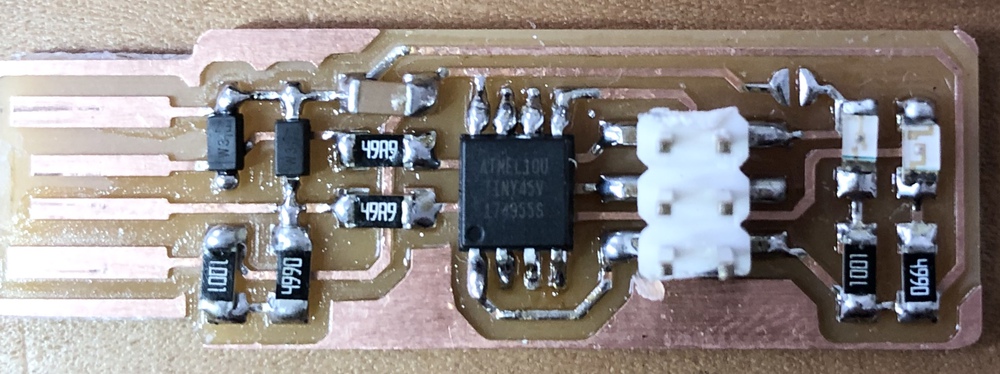
Dsign of FabTinyISP(Brian)
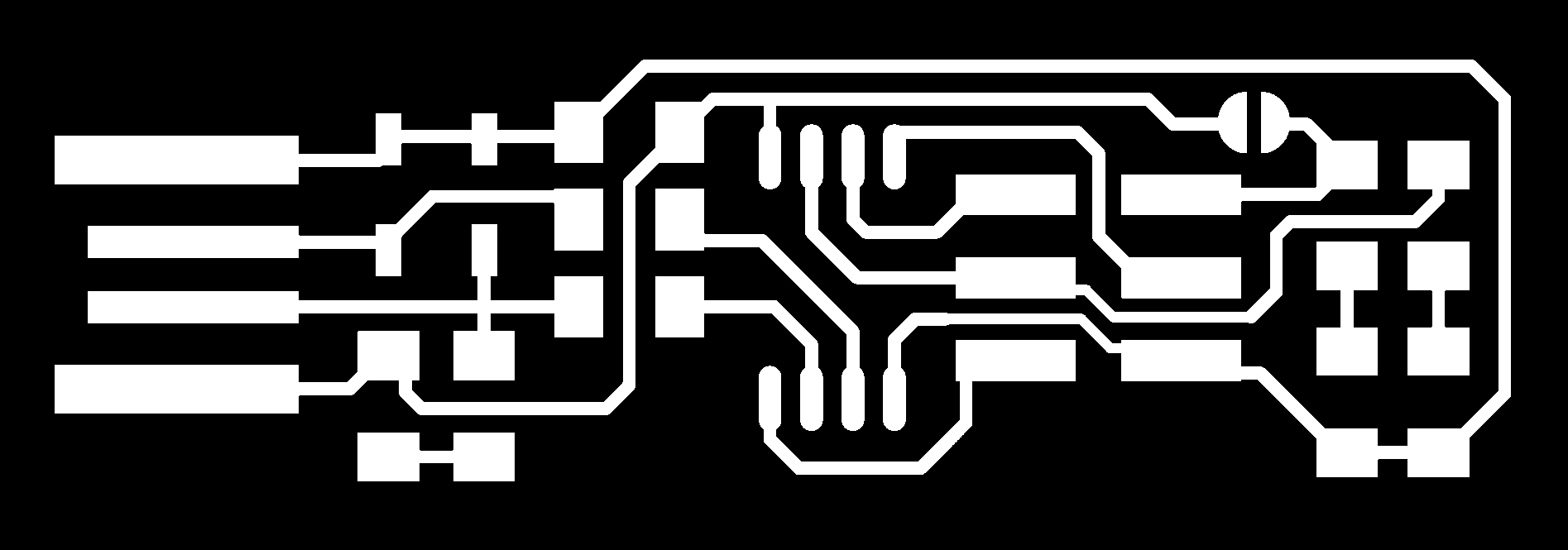

_pcb_full.png)
_schematic.png)
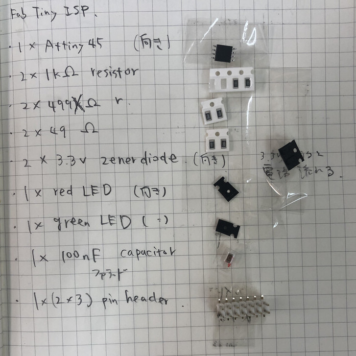
- 1x ATtiny45 or ATtiny85
- 2x 1kΩ resistors
- 2x 499Ω resistors
- 2x 49Ω resistors
- 2x 3.3v zener diodes
- 1x red LED
- 1x green LED
- 1x 100nF capacitor
- 1x 2x3 pin header
CAM
As I described in group assignment, When I firstly did a test cut and cut my ISP by mods, the tool did not work on “set to origin”. When I click that button, that was applied in the mods(browser). However, MDX15 did not start from the value (set as “origin”) but started from (x=0, y=0). Therefore I changed and run from Fab Modules.
Note:This issue was solved by clicking “calculate” in mods AFTER set origin at "Roland MDX-20 milling machine" in mods. (Otherwise, the parameters of "origin" at the Roland MDX-20 Milling Machine is not applied to the CNC and end mill starts from x:0, y:0.)
Configuration process via mods is written in group assignment page.
Configuration process via Fab Modules
- Use "Image (.png)" tab (select image file in png format)
- Use "Roland mill(.rml)" tab (select machine of "MDX-15")
- process (select PCB traces(1/64) or PCB outline(1/32) etc.)
- set up parameters (machine, speed(mm/s), x0(mm)/y0(mm)/z0(mm), home etc.)
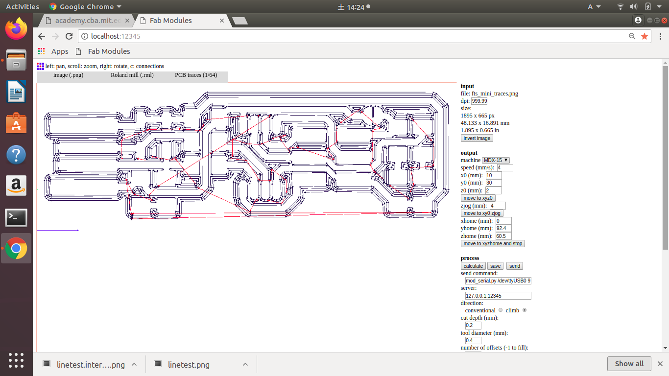
For trace,
- speed(mm/s): 4
- check x0/y/0/z0(origin): where to start cutting
When CNC machine is connected via serial interface, the part of "process" is displayed.
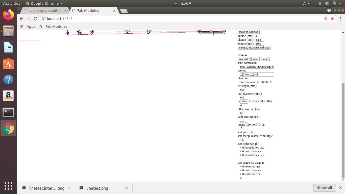
Check:
- cut depth is not greater than tool diameter
- number of offsets and offset overlap.
- displayed path is not cut off and not connected unexpectedly
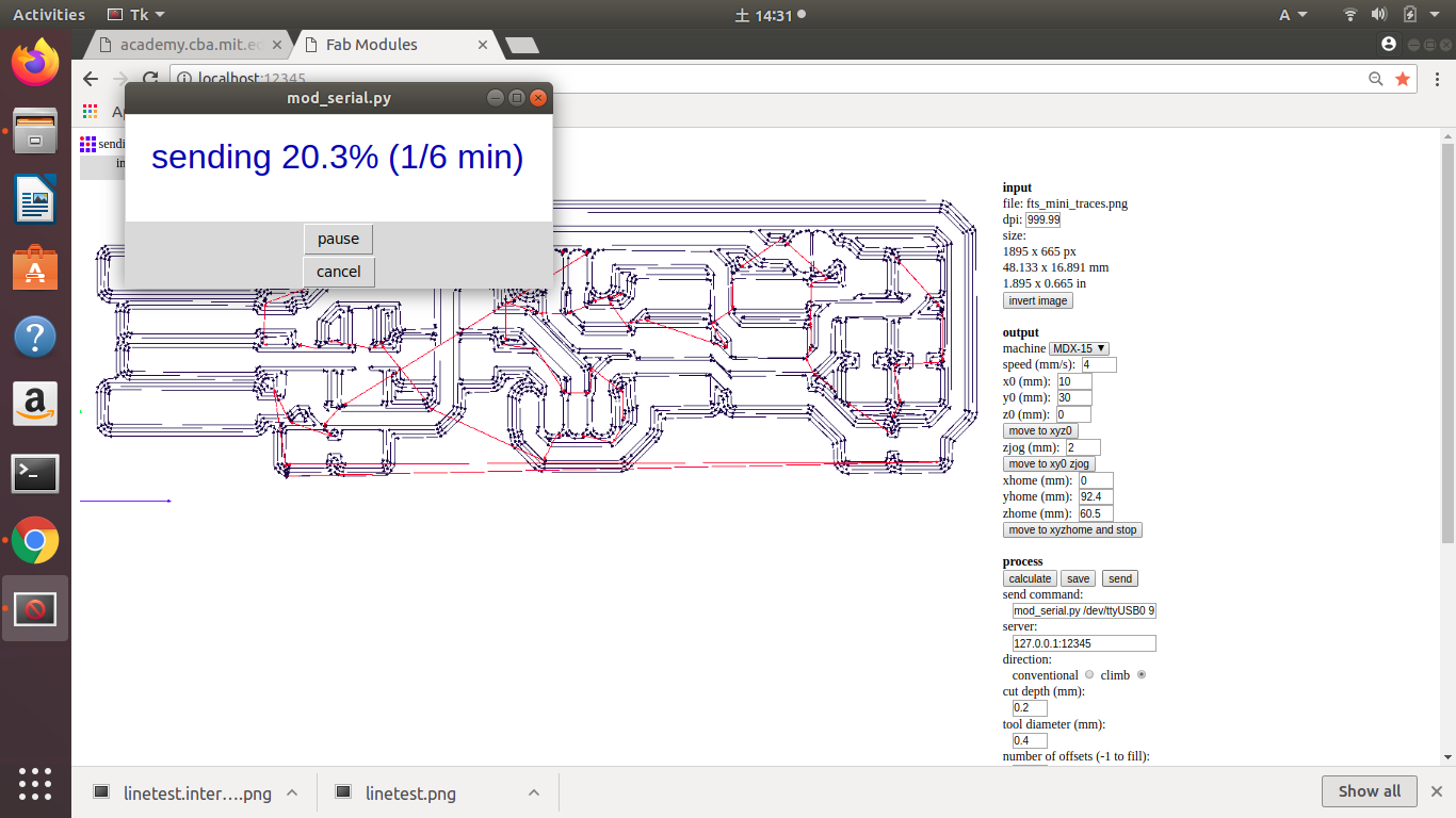
Confirm "send command" is displayed wihthout error. If OK, "send"
If something wrong, "pause" or "cancel" the command
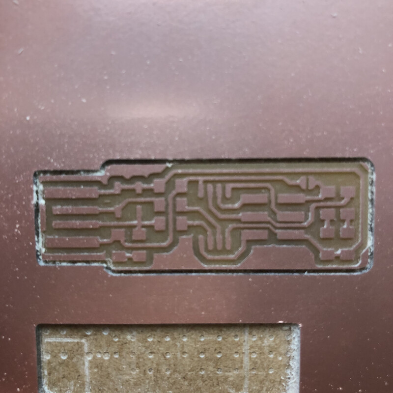
Cutting
Refer to Set up with mods and Trace and Cut in group assignment page.
Assembly
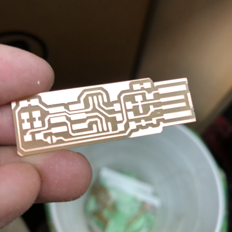
1. Cut off the FabTinyISP from PCB. Peal off using solvent
Solvent is used for pealing off sticker without damaging a paper
2. Clean up the surface with scrubbing brush and dish washing detergent.
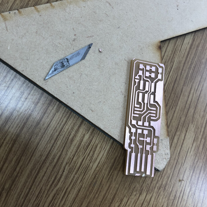
3. Peal off the edge part with microwave cutter. (the image is when I configure the blade of the cutter)
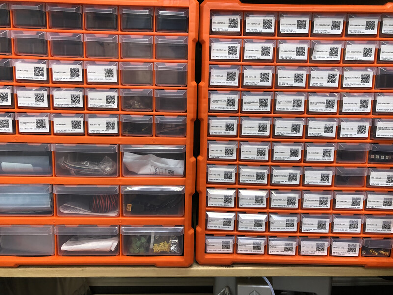
4. Get the parts from Fablab Kannai's parts case.
5. Put the tape on my paper notebook and paste it otherwise tiny parts goes away. Actually I lost one green LED, unfortunately...
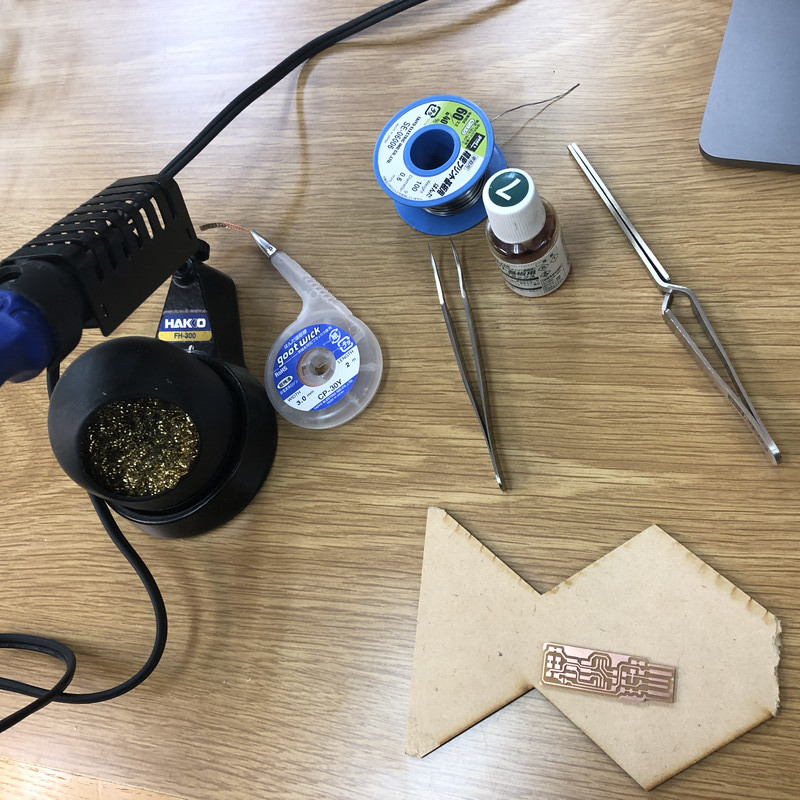
6. Solder : Soldering iron, iron table, desoldering wire, solder, tweezers, soldering flux
7. Learning about soldering. Pretinning(予備はんだ) is very effective to solder tiny parts
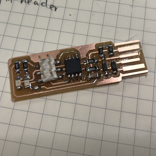
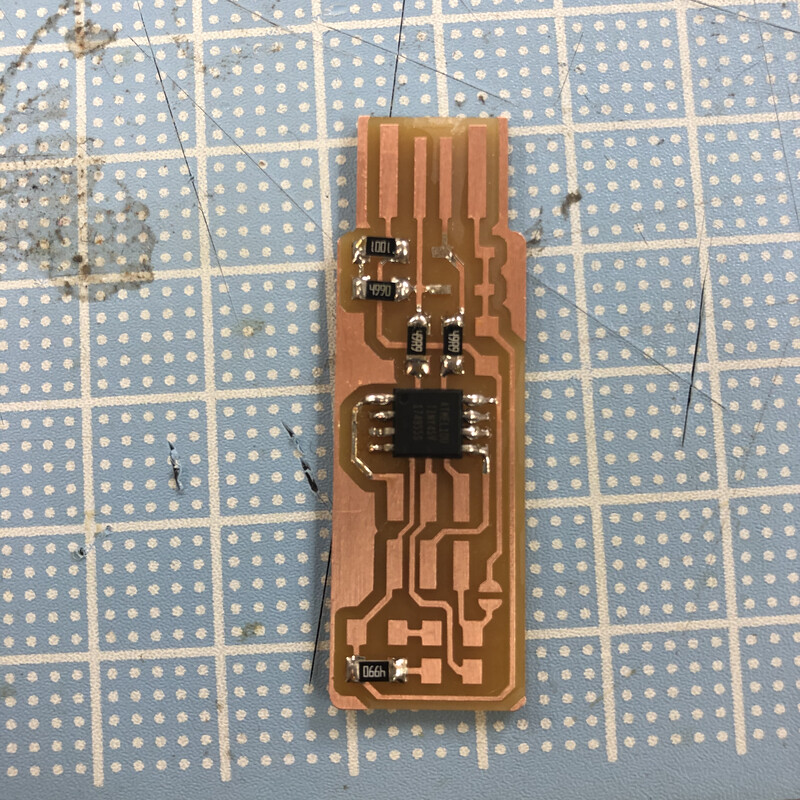
8. Completion!
So many points to be improved though;)
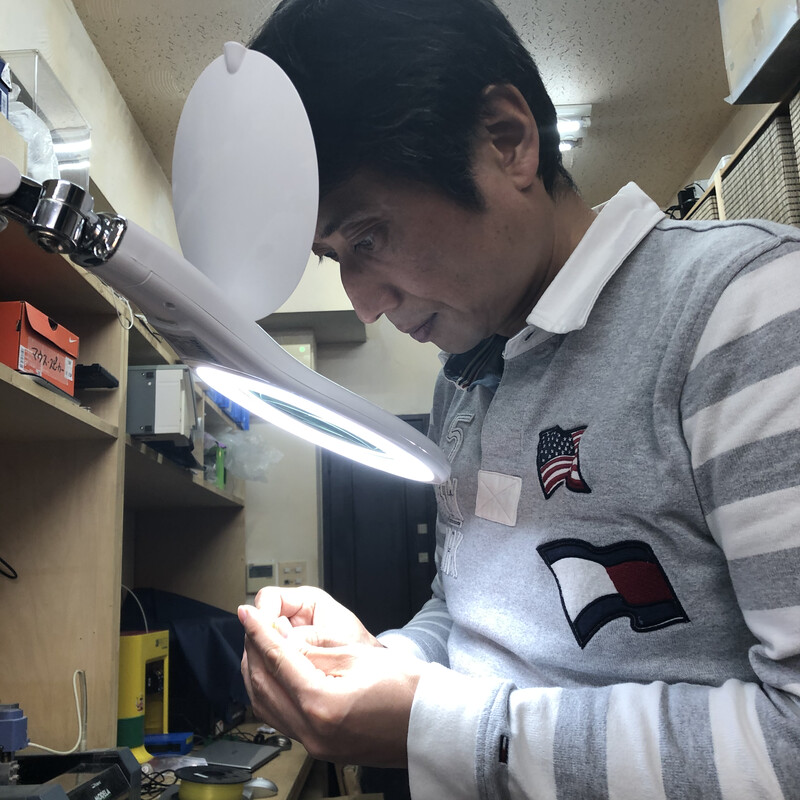
9. Checked by my instructor, Tamiya-san
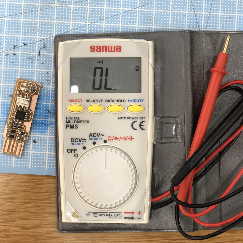
10. Check the path using a multimeter.
My first FabTinyISP!!
Make my FabTiny a Programmer
I tried several ways to make my FabTiny as a Programmer
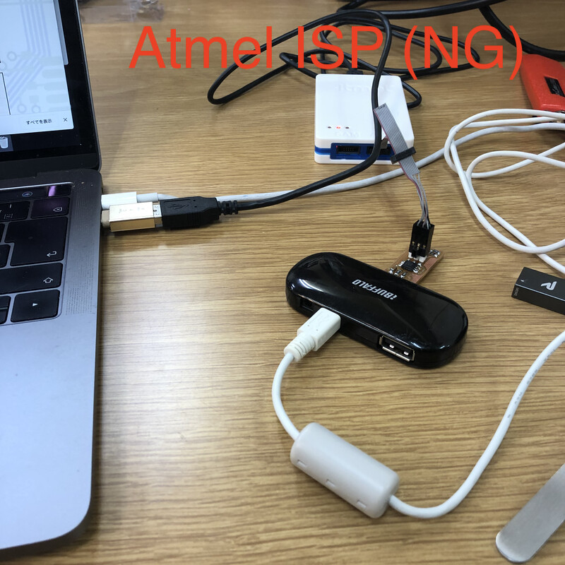
- Mac(usb type C) - (usb type C-A adapter) - Atmel ISP - (FTDI) - my FabTiny - (usb type A-C adapter) - Mac(usb type C) →NG
- Mac(usb type C) - (usb type C-A adapter) - FabTiny ISP(at Kannai) - (FTDI) - my FabTiny - (usb type A-C adapter) - Mac(usb type C)→NG
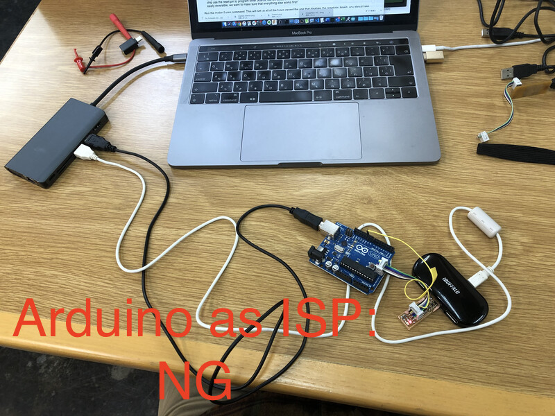
- Mac(usb type C) - (usb type C-A adapter) (usb type A-B cable)- Arduiono ISP - (FTDI) - my FabTiny - (usb type A-C adapter) - Mac(usb type C)→NG
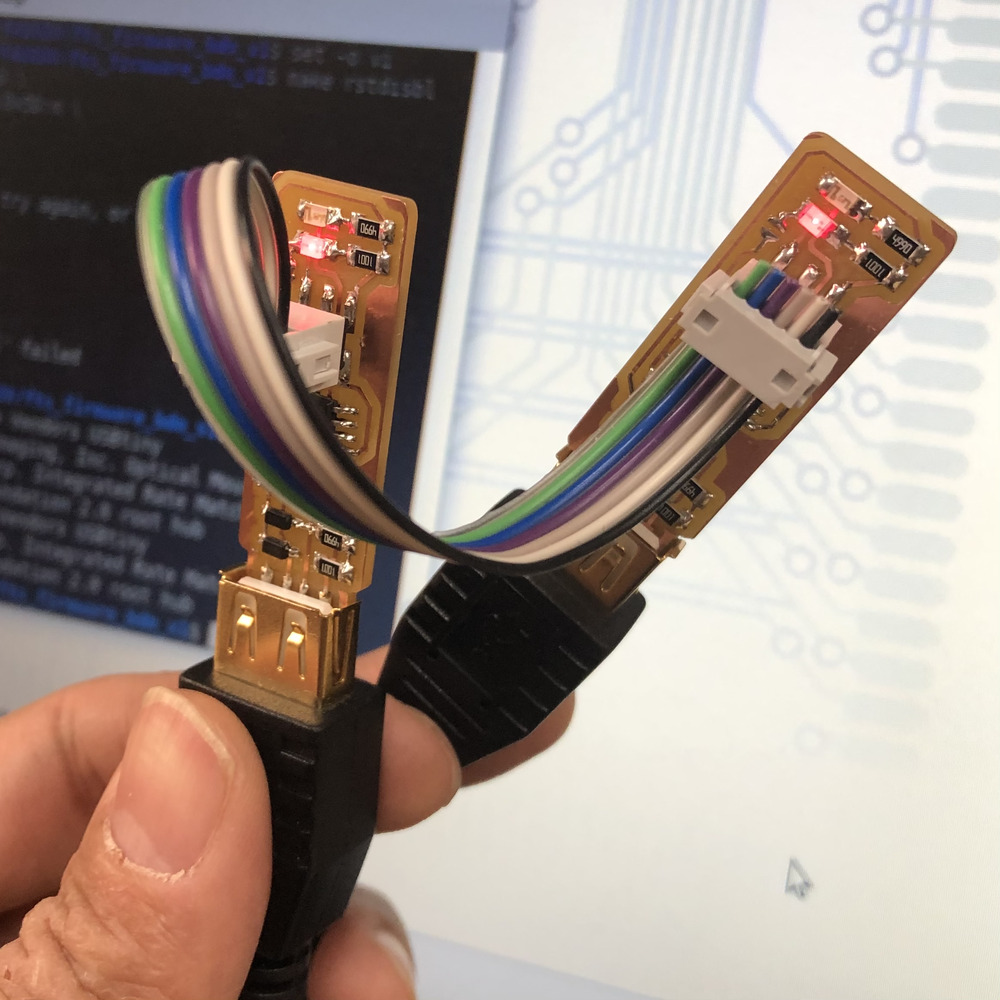
- Linux xbuntu(usb type A) - FabTiny ISP(at Kannai) - (FTDI) - my FabTiny - (usb type A-C adapter) - Mac(usb type C)→OK!
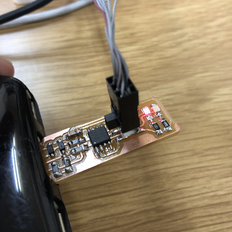
My FabTiny is put on the light when FTDI cable is plugged from the other ISP.
However, it did not work using Mac at this point.
- Download CrossPack →NG
- Download MacPorts →I did not use MacPorts because my local package manager is Homebrew.
- Install avrdude via Homebrew (
brew install avrdude)→OK!
$ which avrdude shows the directory of avrdude as /usr/local/bin/avrdude in my mac. After this, my mac worked as a client of ISP successfully!!!
Following source code of makefile worked finally. On linux(xubuntu), default source file worked in a straight forward way. Commented out (# XXX) descriptions are what I tried before finalizing this work.
/Users/tatsuro.homma/firm/fts_firmware_bdm_v1/Makefile
      # Brian Mayton
      #
      # 'make' builds the .hex file.
      # 'make flash' uses the programmer to load it onto the target chip.
      # 'make fuses' programs the fuse bits on the target chip.
      # 'make rstdisbl' blows the reset fuse.
      # 'make clean' removes all autogenerated files.

      # OBJECTS should list all of the object files for the program (e.g. for each
      # .c file, list a corresponding .o file here.)  APPLICATION just specifies the
      # name of the hex/elf files, and can be whatever you want.
      OBJECTS = main.o usbdrv/usbdrv.o usbdrv/oddebug.o usbdrv/usbdrvasm.o
      APPLICATION = fts_firmware

      # Set up which MCU you're using, and what programmer, and the clock speed
      # here.
      MCU = attiny45
      PROGRAMMER ?= usbtiny  #←USB Tiny as ISP
      #PROGRAMMER ?= stk500v1  #←Arduino as ISP
      #PROGRAMMER ?= atmelice_isp  #←USB Tiny as ISP
      F_CPU = 16500000UL

      # Fuse bit settings
      EFUSE=0xFF
      HFUSE=0xDD
      LFUSE=0xE1

      # Fuse bit settings with reset pin disabled
      HFUSE_RSTDISBL=0x5D

      # Edit these if you want to use different compilers
      CC = avr-gcc
      OBJCOPY = avr-objcopy
      SIZE = avr-size
      AVRDUDE = avrdude

      # Compiler and linker flags
      CFLAGS=-mmcu=$(MCU) -Wall -DF_CPU=$(F_CPU) -I. -funsigned-char \
              -funsigned-bitfields -fpack-struct -fshort-enums -Os -Iusbdrv
      LDFLAGS=-mmcu=$(MCU)

      all: $(APPLICATION).hex

      clean:
              rm -f usbdrv/*.o
              rm -f *.hex *.elf *.o

      %.hex: %.elf
              $(OBJCOPY) -j .text -j .data -O ihex $< $@

      $(APPLICATION).elf: $(OBJECTS)
              $(CC) $(LDFLAGS) -o $@ $^
              $(SIZE) -C --mcu=$(MCU) $@

      %.o: %.c
              $(CC) $(CFLAGS) -c $< -o $@

      %.o: %.S
              $(CC) -x assembler-with-cpp $(CFLAGS) -c $< -o $@

      flash: all
              $(AVRDUDE) -p $(MCU) -c $(PROGRAMMER) -P usb -e \
              -U flash:w:$(APPLICATION).hex
      #        $(AVRDUDE) -p $(MCU) -c $(PROGRAMMER) \
      #               -P /dev/cu.usbmodem143401 \ #←usb port number
      #               -b19200  #←serial communication rate
      #               -e -F \ #←F: force
      #               -U flash:w:$(APPLICATION).hex

      fuses:
              $(AVRDUDE) -p $(MCU) -c $(PROGRAMMER) -P usb \
                      -U lfuse:w:$(LFUSE):m -U hfuse:w:$(HFUSE):m \
                      -U efuse:w:$(EFUSE):m
      #        $(AVRDUDE) -p $(MCU) -c $(PROGRAMMER) -P usb \
      #               -P /dev/cu.usbmodem143401 \ #←usb port number
      #               -b19200  #←serial communication rate
      #               -e -F \ #←F: force
      #               -U lfuse:w:$(LFUSE):m -U hfuse:w:$(HFUSE):m \
      #               -U efuse:w:$(EFUSE):m

      rstdisbl:
              $(AVRDUDE) -p $(MCU) -c $(PROGRAMMER) -P usb \
                      -U lfuse:w:$(LFUSE):m -U hfuse:w:$(HFUSE_RSTDISBL):m \
                      -U efuse:w:$(EFUSE):m

      .PHONY: all clean install fuses
From terminal on linux,
$ make
$ make flash
$ make fuses
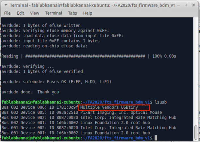
$ lsusb # confirmed whether my FabTinyUSB is recognized as usb device on Linux
$ make rstdisbl
Here is response from terminal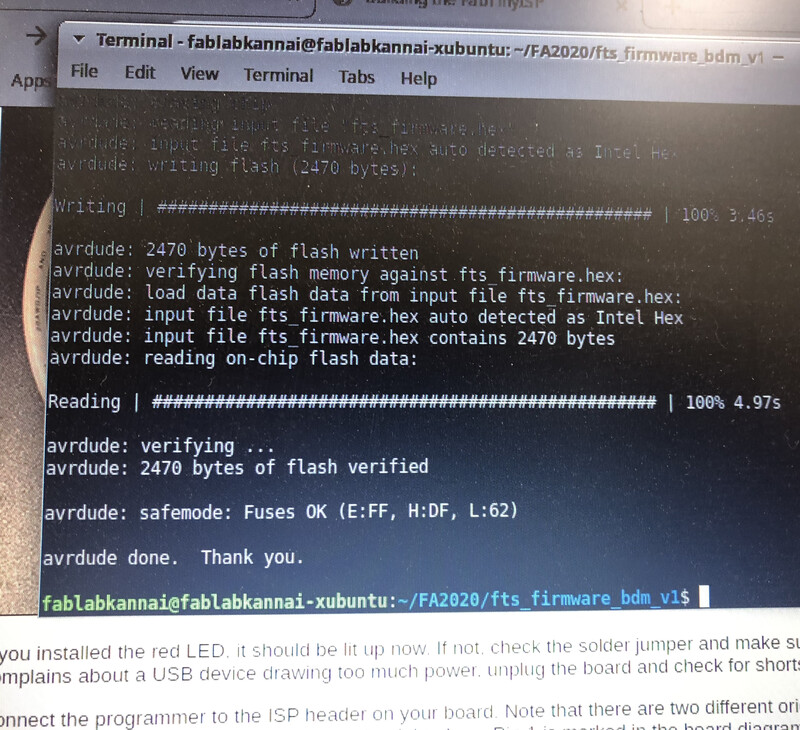
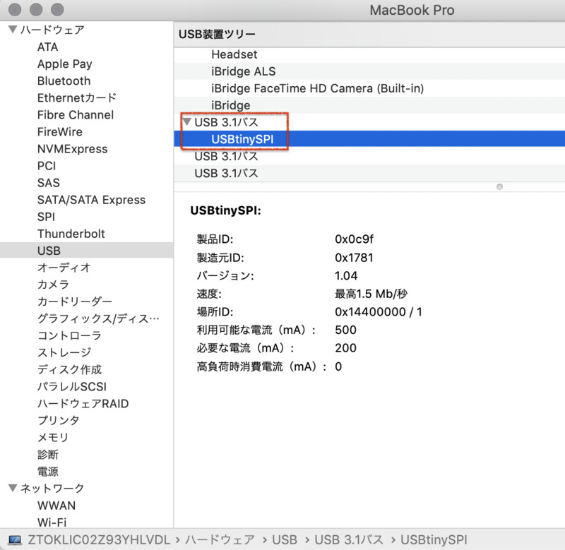
After all of above work, my FabTinyISP is recognized as a USB device on linux and on mac as well.
Write program to the other boards
Make another ISP (from linux)
Firstly, I write an ISP program from my FabTiny ISP from linux client. I just did the same thing as above process of "Make my FabTiny ISP" from my brandnew FabTiny ISP.
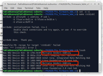
lsusb return two devices of "USBTiny"!
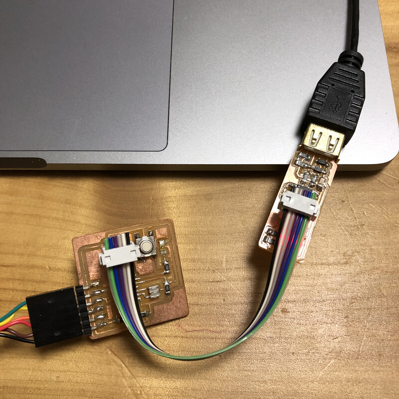
Write a program to echo board (from mac)
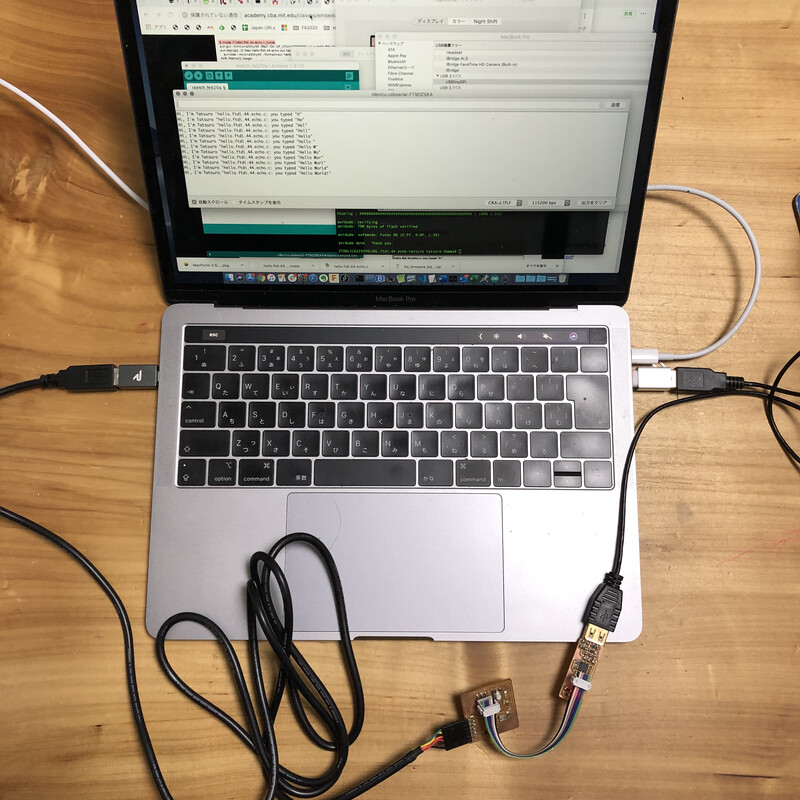
Secondally, I connected my FabTiny and "echo board" that I rent from Tamiya-san.
Connection- Mac(usb type C) - (usb type C-A adapter) - my FabTiny(programmer) - (FTDI) - "echo board"(target) - (usb type A-C adapter) - Mac(usb type C)
I updated a echo program that receive and send a charactor via serial communication.
The program I updated is from Attiny45 - echo.c inEmbedded Programming in FabAcademy
      int main(void) {
      //
      // main
      //
      static char chr;
      static char buffer[max_buffer] = {0};
      static int index;
      //
      // set clock divider to /1
      //
      CLKPR = (1 << CLKPCE);
      CLKPR = (0 << CLKPS3) | (0 << CLKPS2) | (0 << CLKPS1) | (0 << CLKPS0);
      //
      // initialize output pins
      //
      set(serial_port, serial_pin_out);
      output(serial_direction, serial_pin_out);
      //
      // main loop
      //
      index = 0;
      while (1) {
          get_char(&serial_pins, serial_pin_in, &chr);
          put_string(&serial_port, serial_pin_out, "Hi, I'm Tatsuro \""); //←Added small text
          put_string(&serial_port, serial_pin_out, "hello.ftdi.44.echo.c: you typed \"");
          buffer[index++] = chr;
          if (index == (max_buffer-1))
            index = 0;
          put_string(&serial_port, serial_pin_out, buffer);
          put_char(&serial_port, serial_pin_out, '\"');
          put_char(&serial_port, serial_pin_out, 10); // new line
          }
      }
Then from terminal,
        $ make
        $ sudo make -f hello.ftdi.44.echo.tatsuro.c.make program-usbtiny
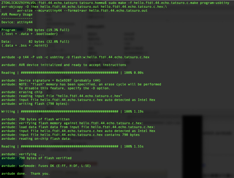
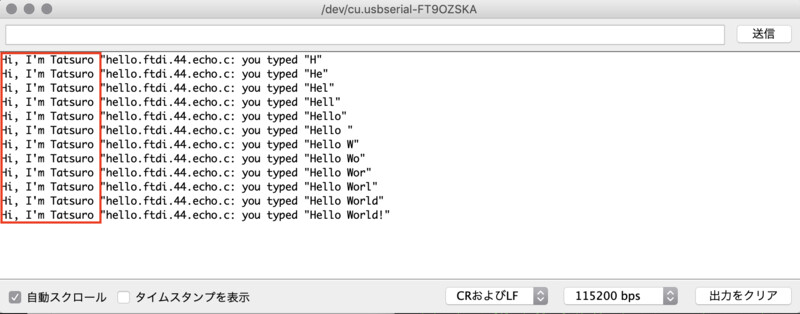
Then echo board echo from/to Arduino serial monitor on mac client.
Lessons Learned
- mods controls the path and calculate the diameter of endmill. From testcut, it looks that 0.01 inch of offset in endmill itself is considered by mods.
- There are bunch of information about avr programmer in website. It's good to follow the recommended procedure (like "highly recommended using linux"). Also, the newer package manager like homebrew works fine.
- I need to train soldering and pretinning through every work at FabAcademy. It gets fun time for me now.