
Electronics Production (week04)
Group Assignment
- Characterize the design rules for your PCB production process
Tool - Endmill
I used following Endmills for this week.
- Shank diameter: 1/8 Inches(3.175mm)
- 0.0100” DIA 220M .010 (0.254 mm) > Shared
- 0.0156” DIA 2FL SE AlTiN 1/64 Inches(0.396875 mm) > MyBit
- 0.0312” DIA 2FL SE AlTiN 1/32 Inches(0.79375 mm) > Shared
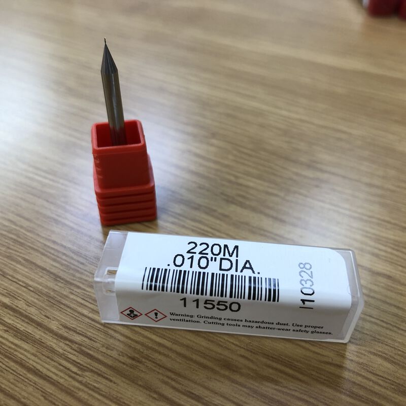
Square End, 0.01 Inch
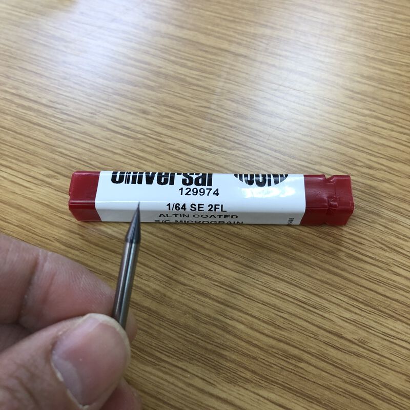
Square End, 1/64 Inch
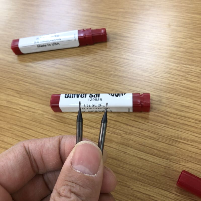
Left: Square End / Right: Ball Nose, 1/32 Inch
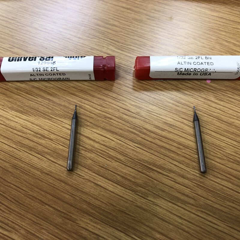
Left: Square End / Right: Ball Nose, 1/32 Inch
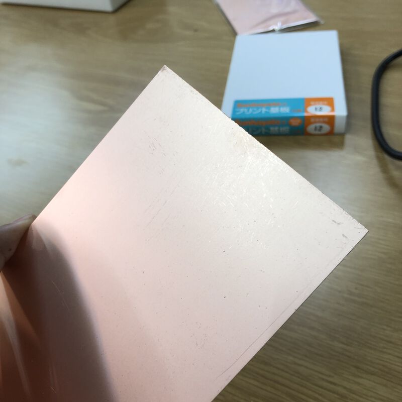
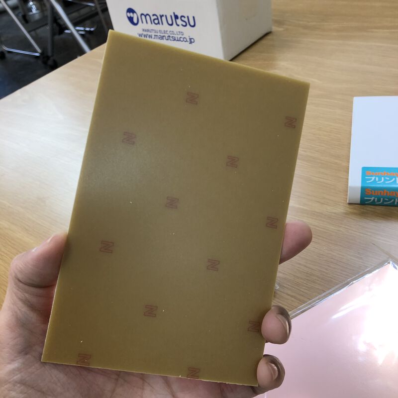
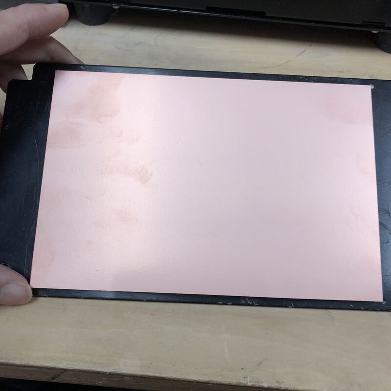
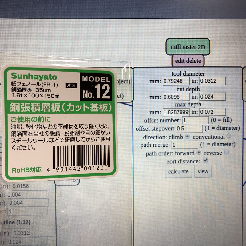
Material - PCB
As a PCB Material, I used a FR1(phenolic paper).
Machine - CNC
CNC at Fablab Kannai is Roland MDX15
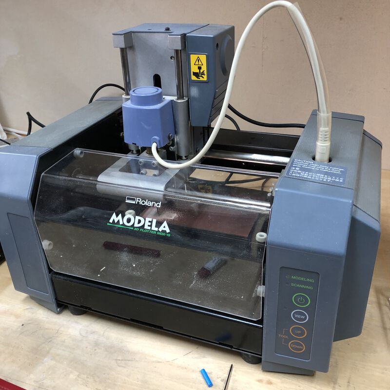
| Product | MDX-15 |
| Operating range | 152.4mm(X)×101.6mm(Y)×60.5mm(Z) |
| Table size | 170mm(X)×110mm(Y) |
| Interface | Serial(RS-232C) |
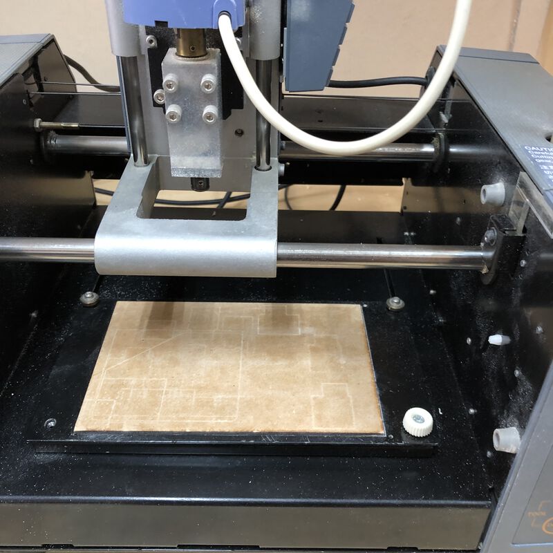
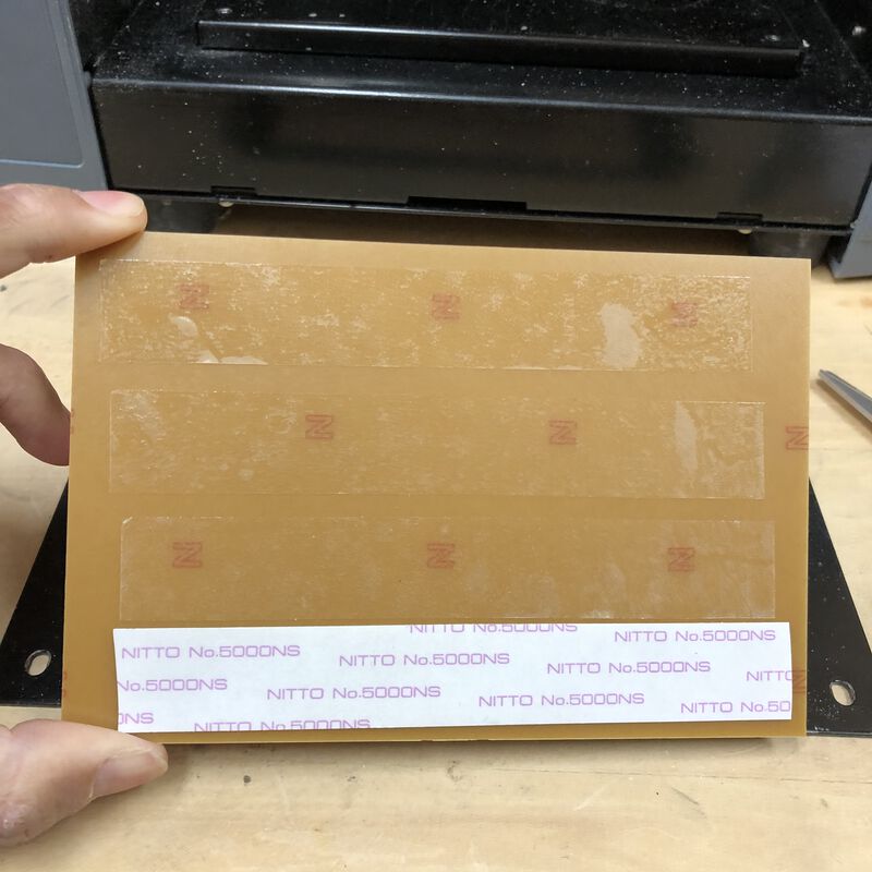
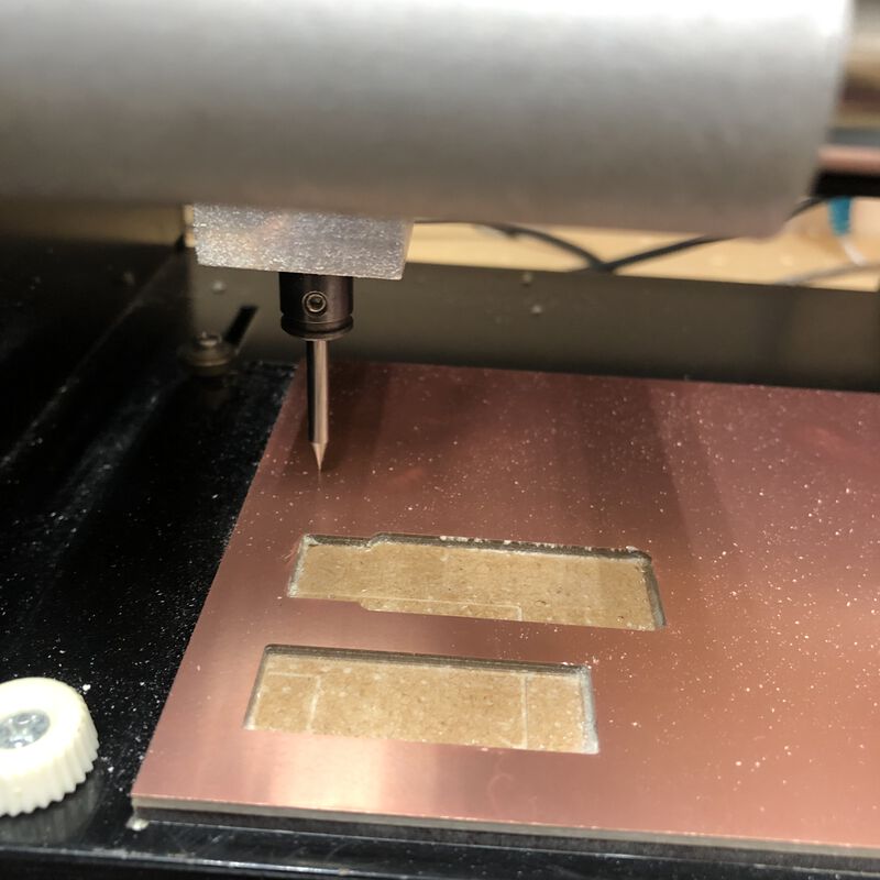
It's important that wasted board on the table to be leveled(flatting)
Fix the PCB sheet on the top of the table with double-side tape
Testcut Data
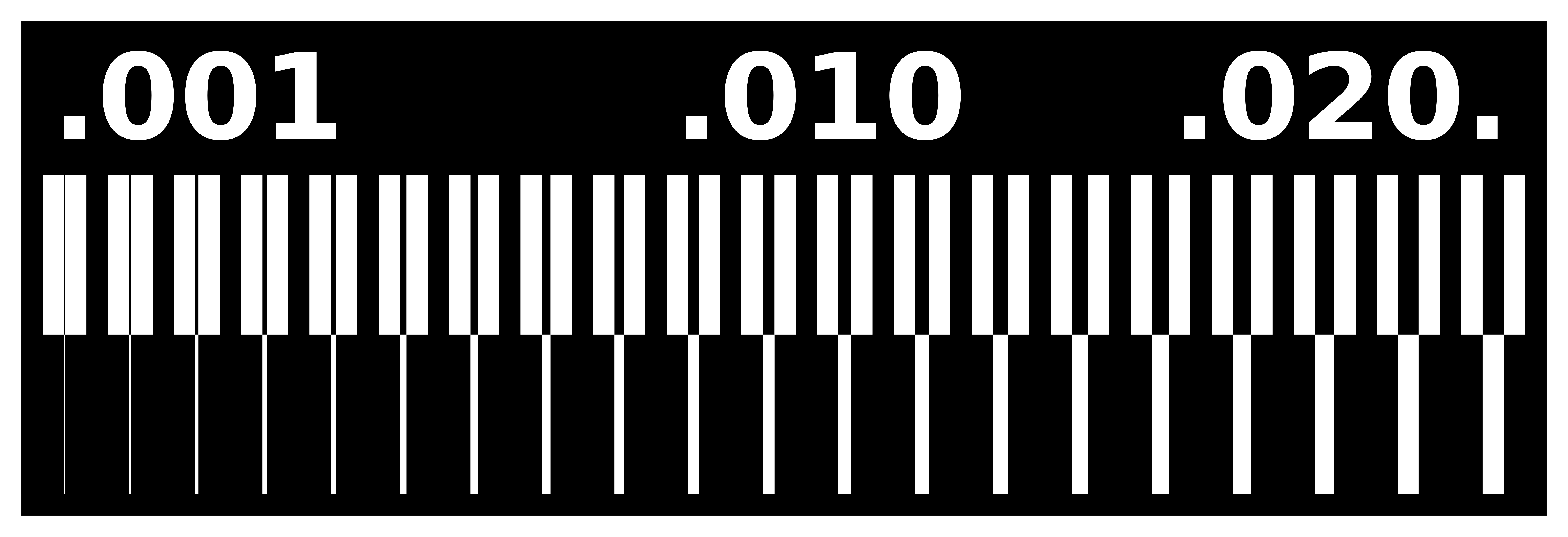
I checked how MDX-15 can be controlled by the instruction of "tarce width" test file, high resolution png files that is provided by FabAcademy.

Machine client - PC, Mods, FabModule
There are two client PC for MDX-15 at Fablab Kannai.
In Feb 2020, lab is setting up an additional client PC. It's because the USB - serial cables depend on softwares on the PC and we want to avoid to re-plug the cables for the time we want to switch the software.
■The original PC(with Raspbery Pi mark)
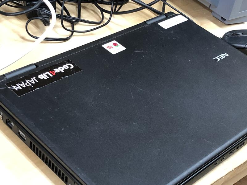
PC with RasPi Mark
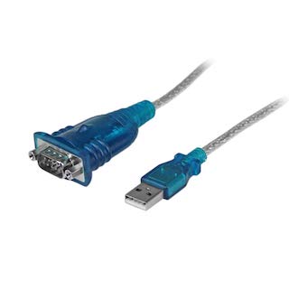
StarTech ICUSB232V2, flow control: RTSCTS
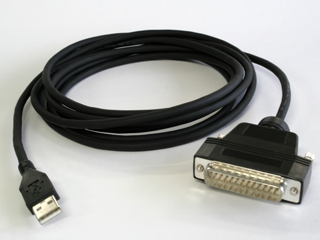
ME-US3, flow control: DSRDTR
After setting up the additional PC, it will not be necessary to use this cable for this PC
- OS: Ubuntu
- PCB milling
- software: Fabmodules
- StarTech ICUSB232V2, flow control: RTSCTS
- OS: Windows
- 2.5D cutting(molding & casting, leveling
- software: Modela Player4
- software: Virtual Modeler
- usb serial cable: ME-US3, flow control: DSRDTR
■Additional PC(with CNC mark)
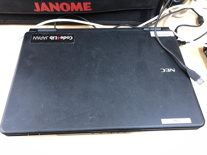
PC with CNC mark
ME-US3, flow control: DSRDTR
- OS: Xubuntu
- PCB milling
- software: mods
- usb serial cable: ME-US3, flow control: DSRDTR
- OS: Windows
- 2.5D cutting(molding & casting, leveling
- software: Modela Player4 (TBD)
- software: Virtual Modeer (TBD)
- usb serial cable: ME-US3, flow control: DSRDTR
■Setup with mods
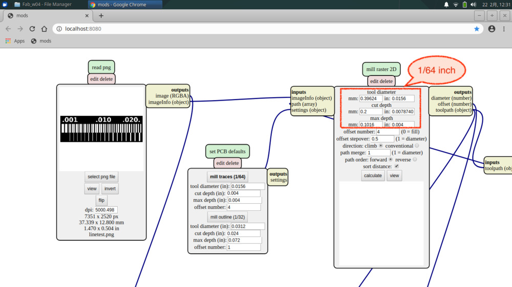
1. read png - select png file
2. set PCB defaults
- "mill traces(1/64"),
- "mill outline(1/32)"
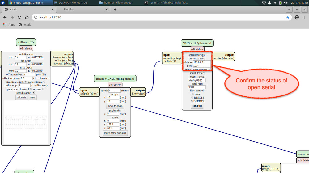
3. Roland MDX-20 milling machine
-x, y position(x:10mm, y:30mm etc.)
-jog height (z:2mm)
4. Raise z axis and set mil
5. mill raster 2D: “calculate”. It looks to be good to click “calculate” AFTER set
origin at Roland MDX-20 milling machine. Otherwise, the parameters of "origin" at the Roland MDX-20
Milling Machine is not applied to the CNC and end mill starts from x:0, y:0.
6. Roland MDX-20 - milling machine ("move to origin”)
<- just in case tool unexpectedly work from the other place
7. WebSocket Python Serial Check the status of serialserver.py (open)
8. WebSocket Python Serial - #Send file"
Raise z axis and set mil
When cutting outline with 1/32 inch end mill,
-set PCB defaults: "mill outline(1/32)"
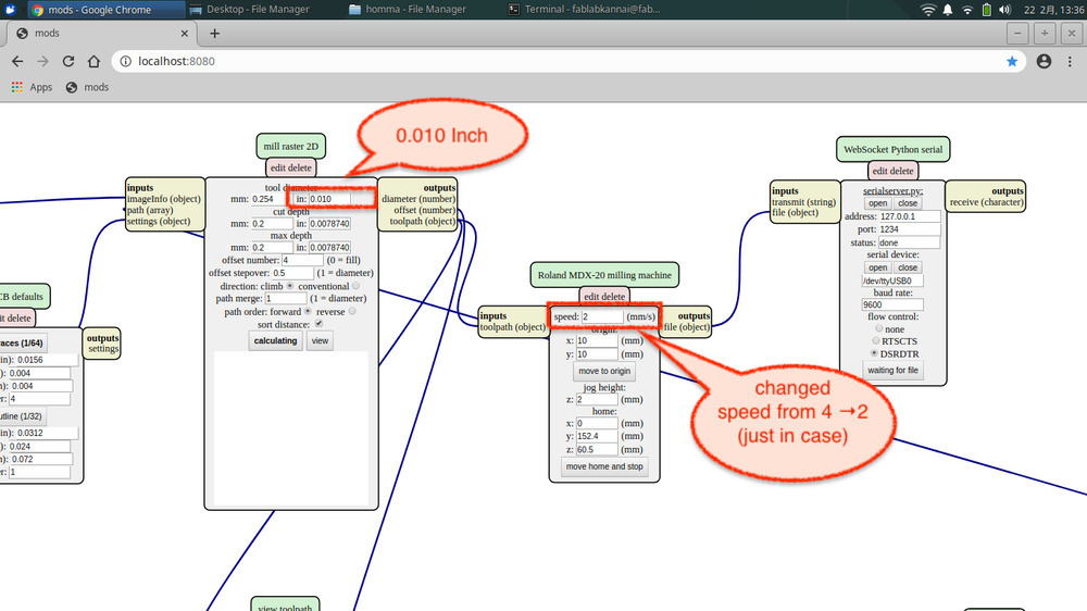
When cutting traces with 0.010 inch end mil,
-mill raster 2D: set tool diameter
Important rule: Cutting depth for 1 time needs to be less than tool diameter.
-Roland MDX-20 milling machine: change speed just in case
-After checking "origin", "calculate
# Check the serial communication process
$ ps -ef | grep -i serial
fablabk+ 754 1 1 12:37 ? 00:01:01 /usr/bin/python3 serialserver.py 127.0.0.1 1234
fablabk+ 2015 1721 0 13:49 pts/0 00:00:00 grep --color=auto -i serial
# kill the serial communication process
$ kill -9 754
$ ps -ef | grep -i serial
fablabk+ 2018 1721 0 13:49 pts/0 00:00:00 grep --color=auto -i serial
# when USB of MDX-15 connected after Linux boot and the error is "permission denied"
$ sudo chmod 777 /dev/ttyUSB0
# Restart the serial communication process
$ cd ~/mods/py
$ python3 serialserver.py 127.0.0.1 1234
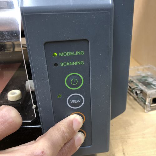 For cancelling the data being processed by CNC, push the button of "A" and "B" at the same time and hold by the
blink at CNC is stopped.
For cancelling the data being processed by CNC, push the button of "A" and "B" at the same time and hold by the
blink at CNC is stopped.
■Trace and Cut
Before cut, close the cover of MDX-15.
After tracing the internal area with 1/64 inch mill, cut the outline with 1/34 inch mill.
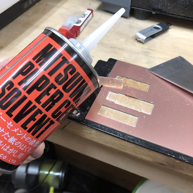
Solvent is a great tool to peal off the cut material
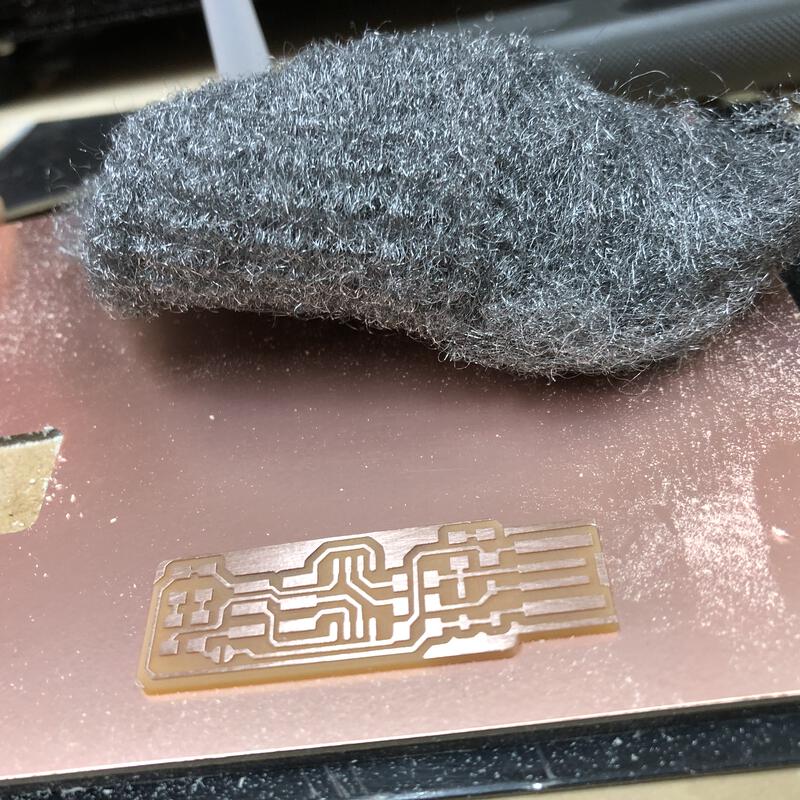
Clean up the surface by steel wool and dish washing detergent.
Evaluation to Test Cut
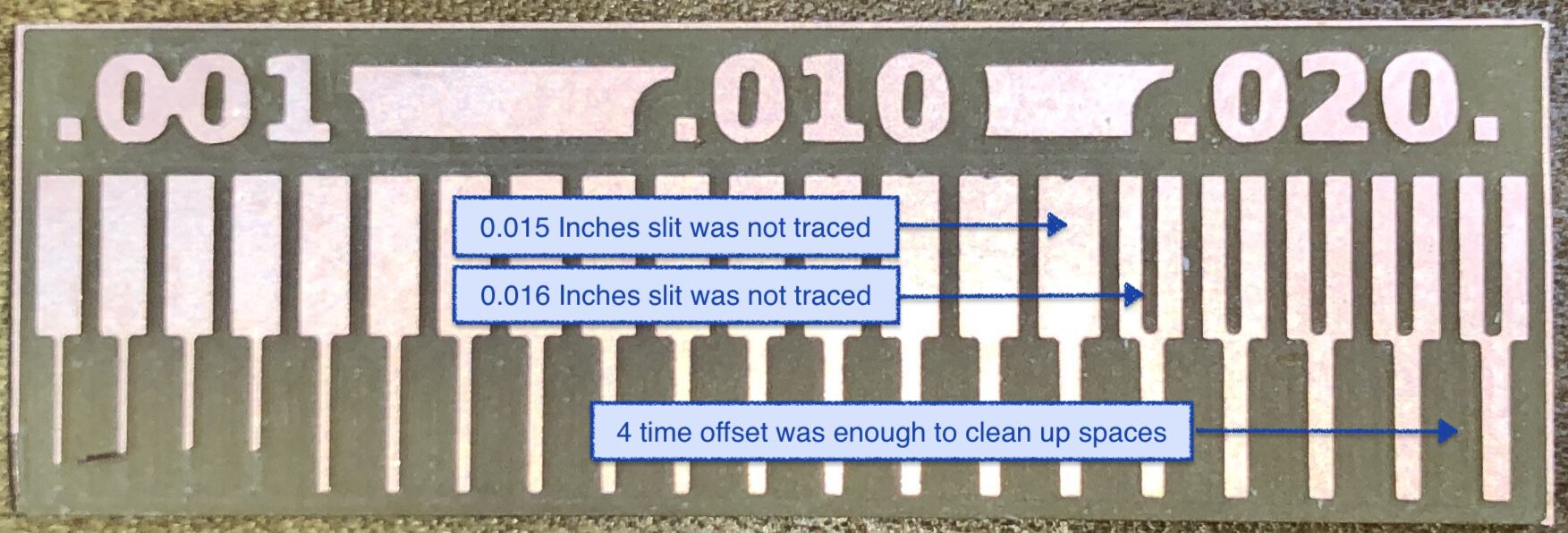
Using 1/64(0.0156) inches endmill, a slit of 0.016 inches slit was traced but 0.015 inches was not.
4 times offset by 1/64 inches endmill was enough to clean up spaces.
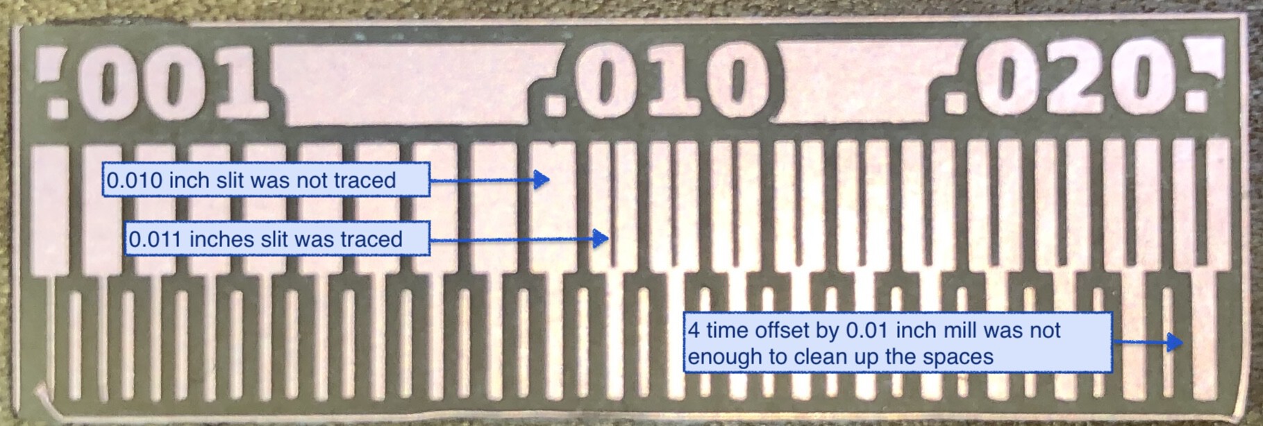
Using 0.01 inches endmill, a slit of 0.011 inches slit was traced but 0.010 inches was not.
4 times offset by 0.010 inches endmill was not enough to clean up spaces.