
Week 5 (3D Scanning and Printing)
Week 5
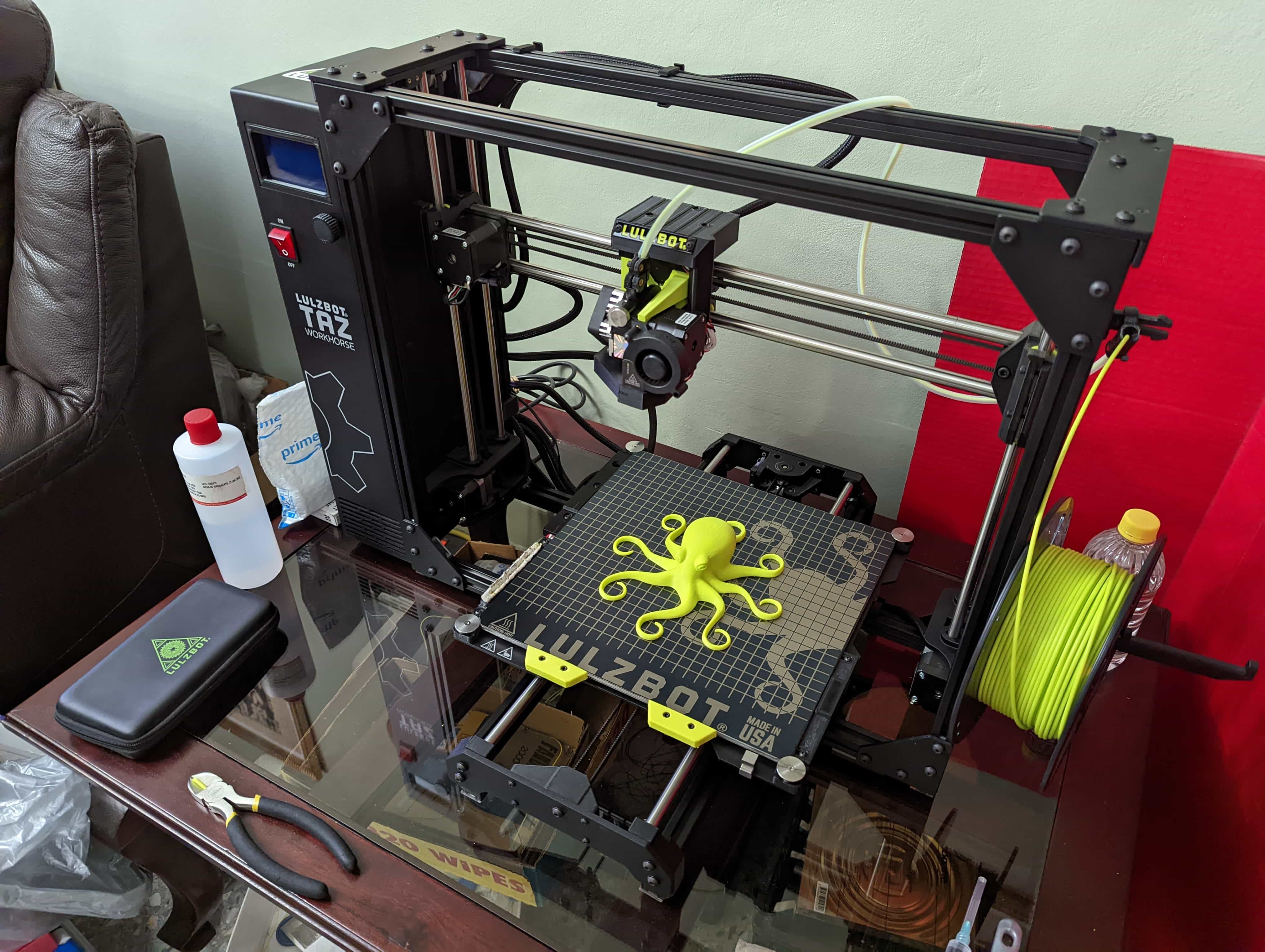
Lulzbot has incredible tolerances on their machines. Honestly in my opinion the 3 main problems that can cause a part to change its dimensions are thermal contraction, warping and the “elephant foot”. These 3 phenomena are present on any price range of FMD (Fused Deposition Modeling) 3D printers. Many variables play a role that could directly affect the severity of these phenomena. More variables could play a role negatively if you don’t have a controlled area around the printer. In my case I don’t have a proper Lab to place my printer. My printer is living in my living room.
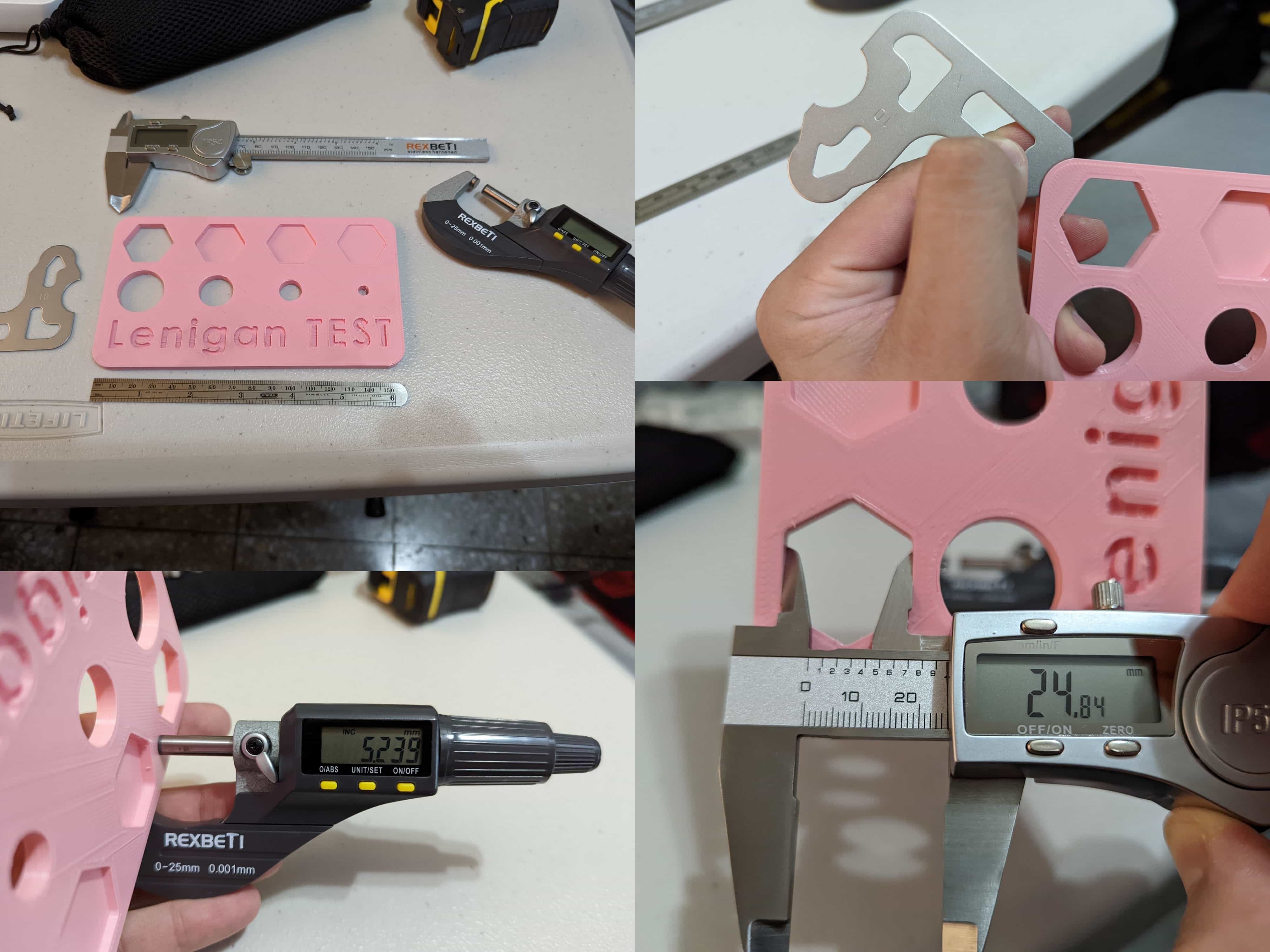
To check the tolerances, I decided to make my one little test board. LulzBot’s Documentation is amazing to verify first party specs. They even have calibration parameter to have the appropriate tolerances. The appropriate range is ±.250mm. I’m definitely in the rang. The only paramter I would change would be to dial down a little the Z-Offset to improve the measurement.
Week 5
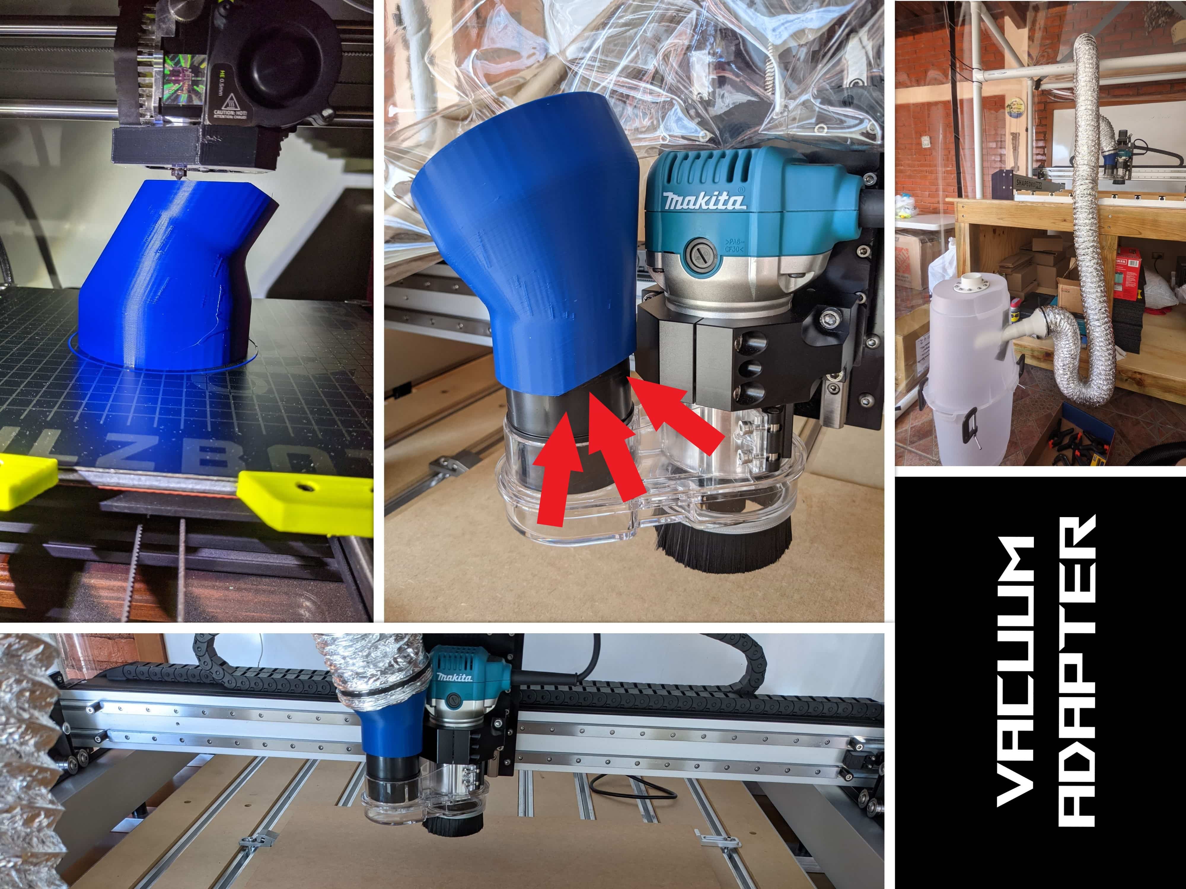
Due to a lack of resources in Honduras most of my things tend to have DIY nature. After getting my CNC I needed tubing for my dust collection system. I have little to work with so I decided to see what tubing I could find and 3D print the adapters. The flexible tube I planned to use had approximately a 10cm. diameter. The diameter was going to be a big problem because I couldn’t make a normal adapter. The adapter would never fit because it to close to the router of my CNC. I decided to make the adapter with a 60° angle. This would solve the problem but easier said then don. I hate making models that require supports so I normally design using my 3D printer’s capabilities to the maximum. Normally if I need supports y try to design my own.
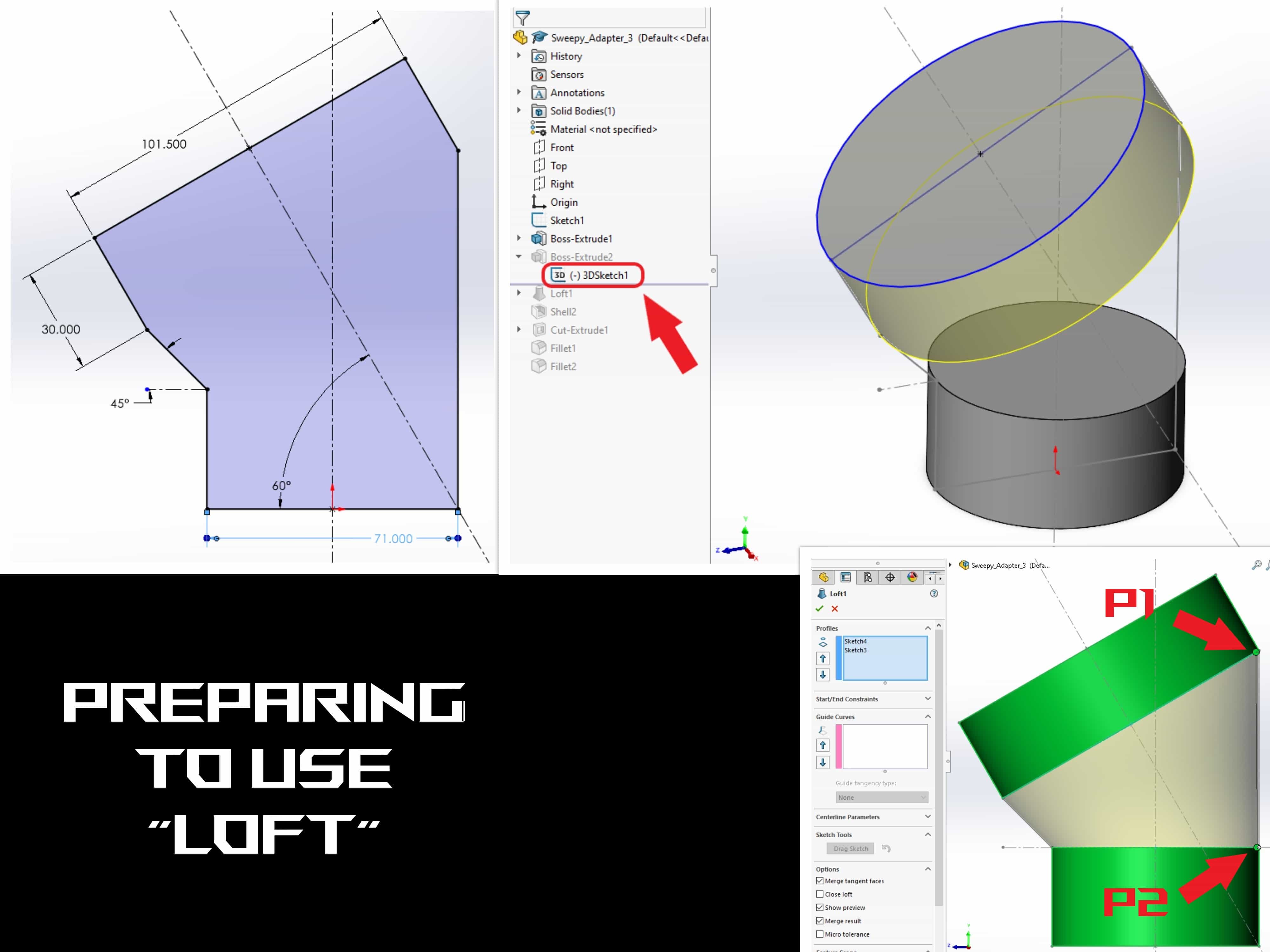
There is no doubt in my mind this is the hardest part I’ve ever had to design. This adapter appears to be harmless but that’s fare from true. After getting the proper measurements with some calipers I started modeling with the proper tolerance. I was sure I was going to use a Loft in Solidworks to make the final shape. The hard part was to set the model in a way that the Loft would make the shape. I tried different methods but none of them was properly working with the Loft. I tried revolve and add new planes. Revolve took too much time and adding the planes for some reason added a bump on a part it meant to be straight.
After a couple of days trying different methods, I came with a different approach. I made a sketch that represented a sagittal plan cut of the adapter. This gave me the parametric outline of what I needed to make. The problematic part was placing the top cylinder on a specific coordinate on the 3D cartesian plane. Sketching on a normal 2D plane made it really complicated, but with a 3D sketch I don’t have any kind of restriction to place a sketch on a specific coordinate. Using the parametric sagittal plan cut works as the constrains to place the cylinder on top. By doing this I was able to create the best rout for the Loft to follow. Then make a 4mm shell and rounded all sharp areas.
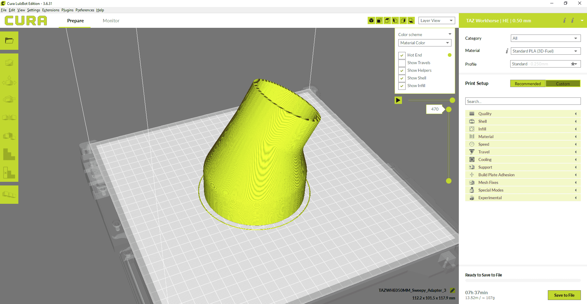
I was so angry that I didn’t completely forgot to take pictures. The nozzle got clogged really bad with only remaining 30 min. to finish the print. My 3D printer is located I the middle of my living room. I don’t have any kind of climatization system to have more control over the temperature in my house. It’s important to mention that Honduras sometimes has crazy weather shifts (morning 15°C, noon 27°C or >). Taking all of this to account I made the hypothesis that the temperature in my house was too high when the clogging happened. With a temperature gun I started measuring temperatures around noon. I was shocked when I saw that the temperature of my roof was higher than the 3D printer’s bed (Bed Temp = 52°C). This means that the air around the nozzle was probable higher o equal to the thermal sink on the nozzle. After I determined this, I’ll never print at noon again unless we are at cold season. Since then, I’ve never had any kind of clogging problems.
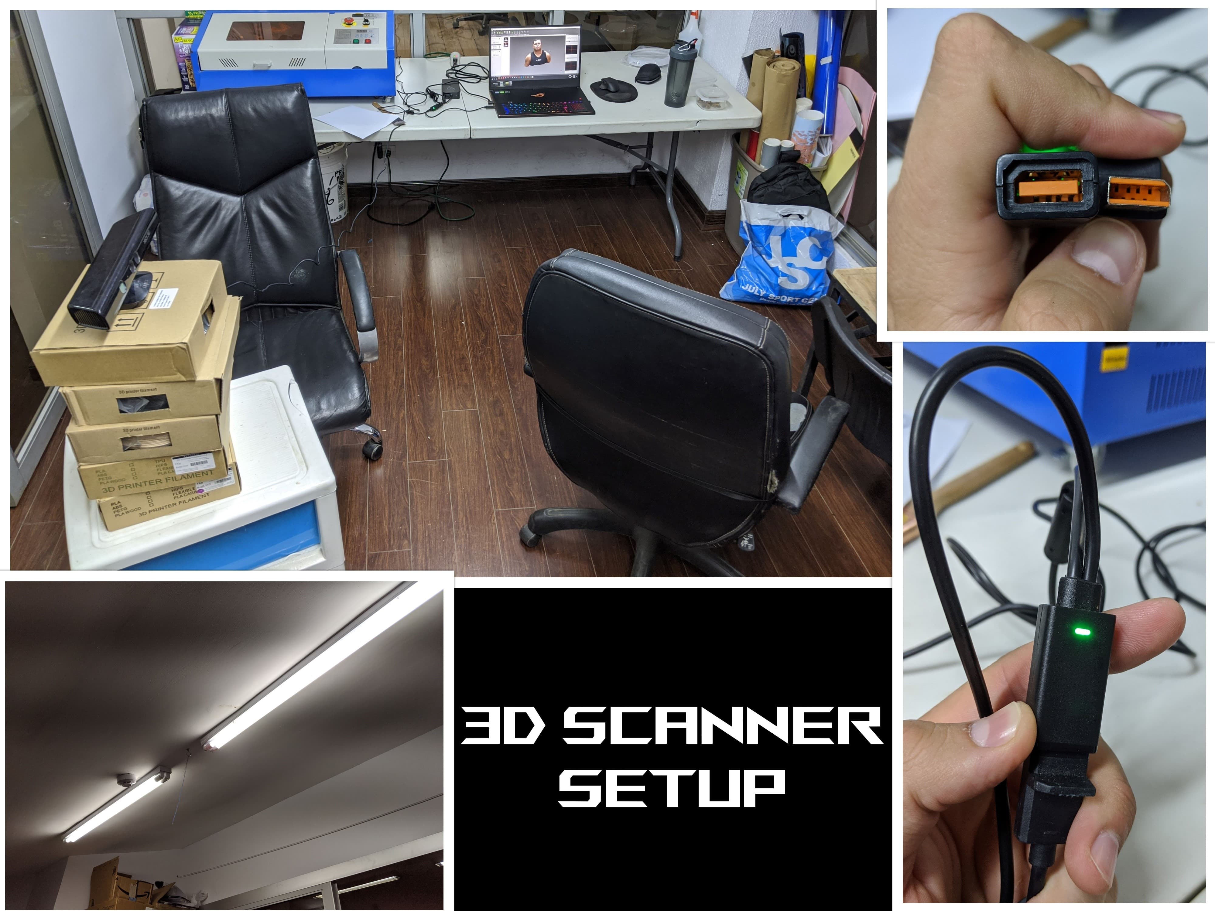
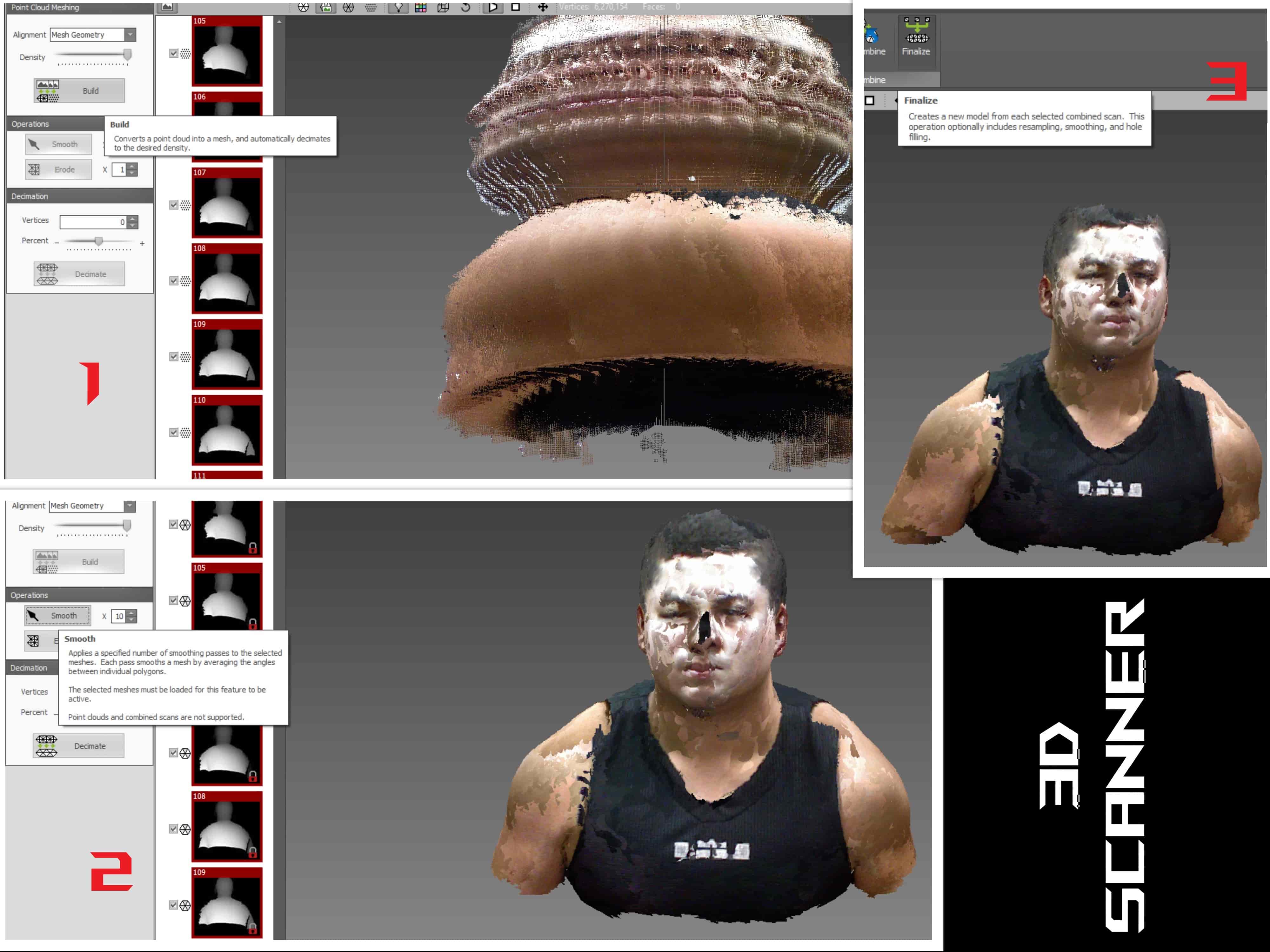
This is great, because you could by one used at a lower price (it works with newer versions of Kinect). I used a tutorial in YouTube to try to setup the best environment to generate the best quality scan I could. Setting up this environment is problematic, because the quality of the scan depends a lot on the light around the scanned object. The black spot on my nose is the shadow that the roof lights created on my face (this can be fixed by adding more lights or playing around with the angles of the light.) The methodology to create the 3D scan s by taking pictures and rotating the object of your selection. The number of pictures taken will determine the quality of the scan (more pictures = better quality of scanned object).
Make (Almost) Anything