
Week 4 (Embedded Programming)
Week 4
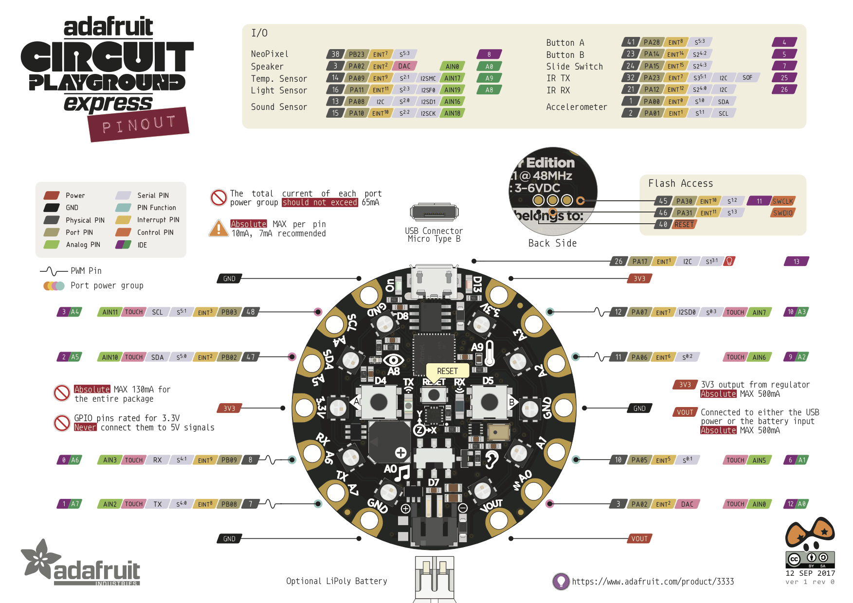
Circuit Playground Express is a different perspective of a developed board. The board round geometry and has alligator-clip pads around it for easier integration of inputs and outputs. Some unique features are mini NeoPixels (10), motions sensor, temperature sensor, sound sensor and more… The express version that I’m using has a ATSAMD21 ARM Cortex M0 MCU, running at 3.3V and a frequency of 48MHz. Please see the following picture to see the Pinout.
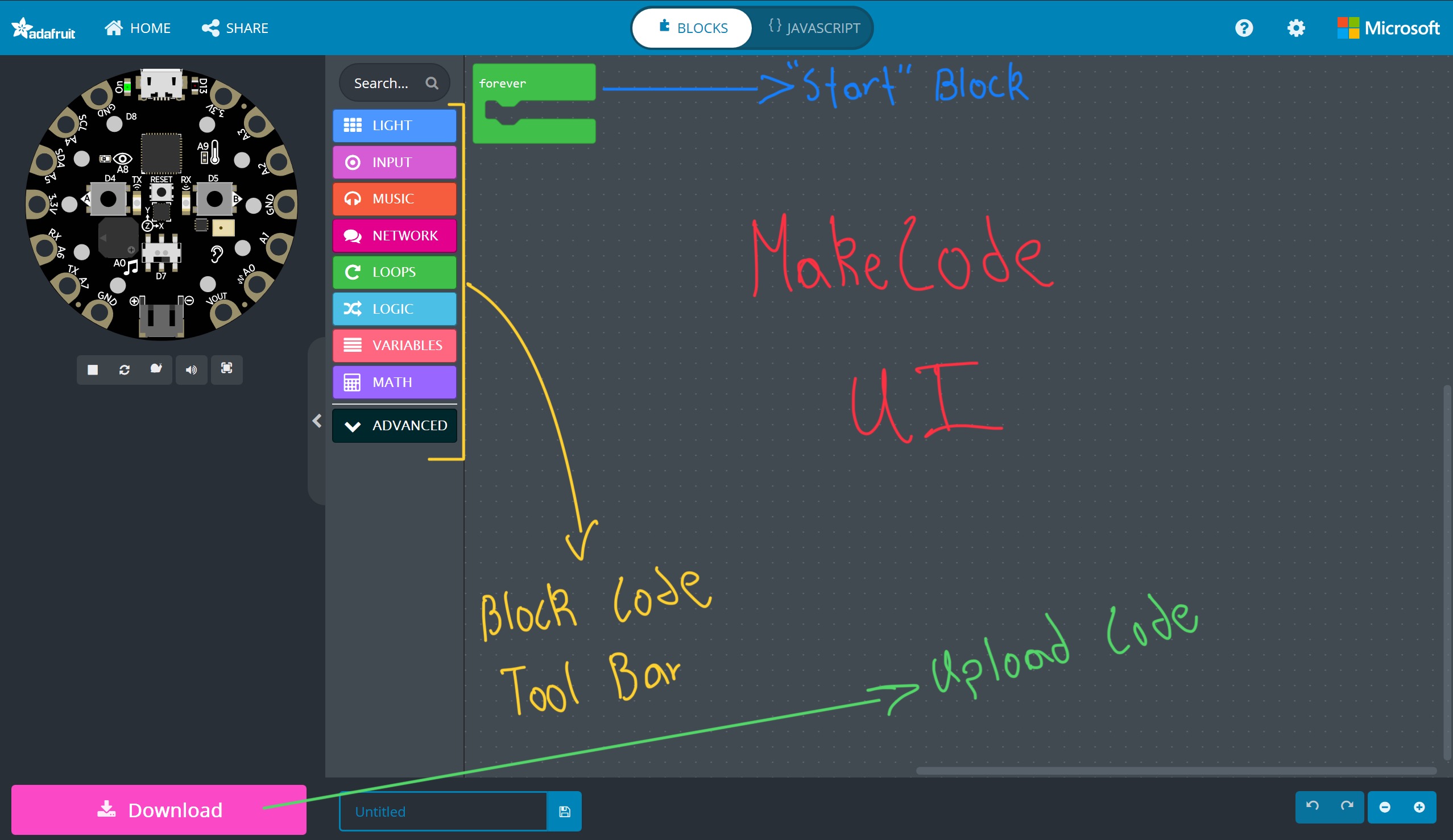
Circuit Playground Express can be programed with MakeCode, CircuitPython, and Arduino IDE. Personally, I felt more interest in MakeCode because it remined me a lot of WOKWI . MakeCode has a cloud and local version (I'll use local) that you can download from the Microsoft store. This way of coding essentially gives you a UI that gives you a block-based coding environment. By dragging the boxes, you get a live representation of what the board will do ones you send the code.
You can code without having a fiscal board but when you have to upload the code to the board it’s a little different then other boards I’ve seen. In the locale version of MakeCode you only have to do this once. We need to put the board in PROGRAMING MODE. First you have to connect the board to a PC and the Neo Pixels will turn on. After that you have to press the RESET button 2 times. The Neo Pixels will turn red and finally green (and open a DRIVE called CPLAYBOOT) if the process was successful. Watch the following video to have better understanding.
Now you only have to drag the blocks to code, download the code and drag the file to the DRIVE called CPLAYBOOT and see the magic happen.
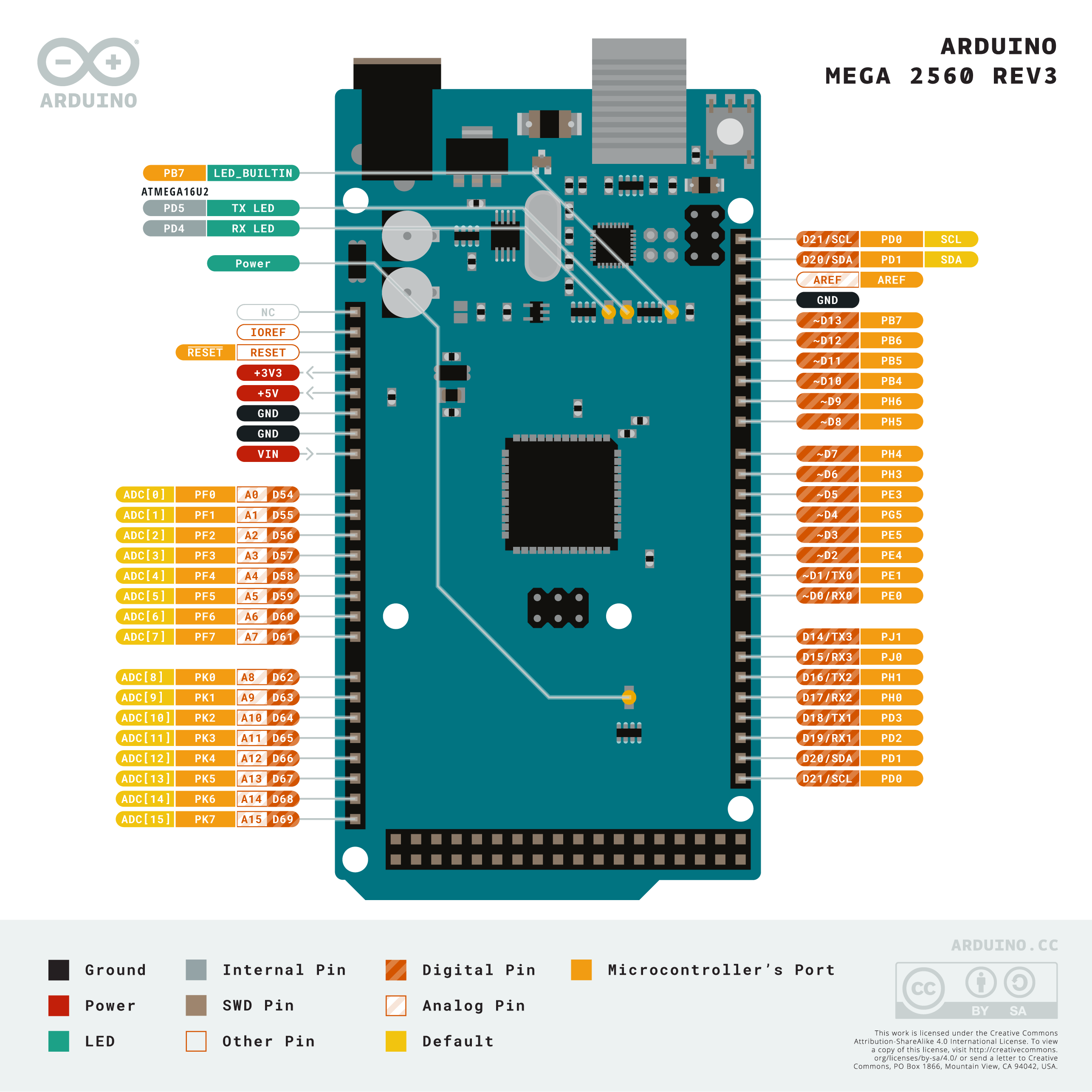
Now I’ll blink the built-in led of an Arduino Mega 2560 Rev3. Arduino boards in general have just one built-in led. We need to write some code using the Arduino variant of C++ in the Arduino IDE. Please see the following picture to see the Pinout.
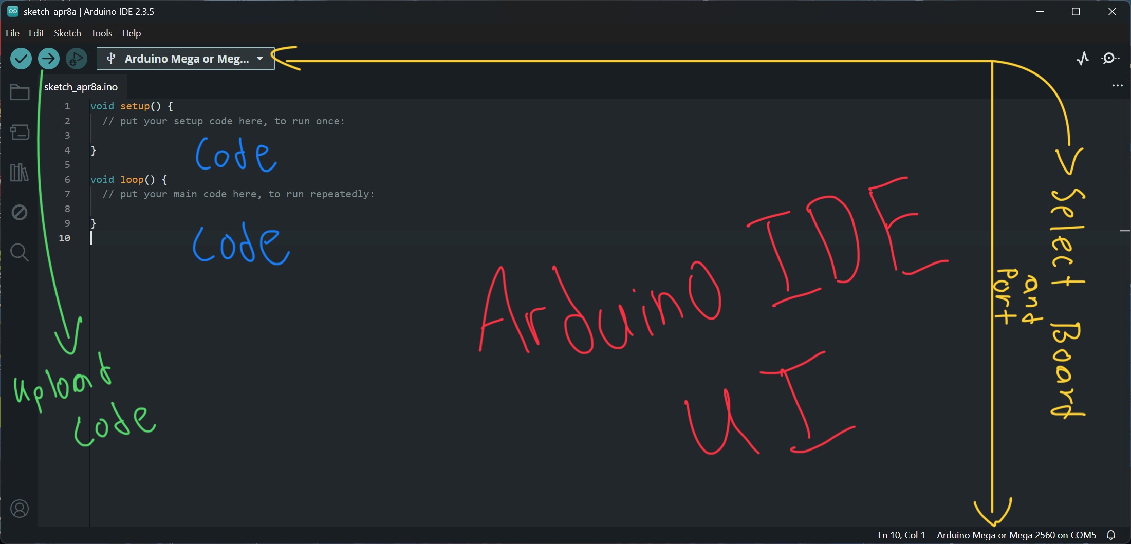
Arduino IDE UI looks more like a typical IDE with some small changes that benefit the interaction with primary Arduino boards but also has the capability of interacting the different brands of developer boards.
Arduino IDE UI looks more like a typical IDE with some small changes that benefit the interaction with primary Arduino boards but also has the capability of interacting the different brands of developer boards.
                  //Walter Lenigan - Fab Academy 2025

                  void setup() {
                    pinMode(LED_BUILTIN, OUTPUT);


                 }

                 void loop() {

                 digitalWrite(LED_BUILTIN, HIGH);   // turn the LED on (HIGH is the voltage level)
                      delay(1000);                       // wait for a second
                      digitalWrite(LED_BUILTIN, LOW);    // turn the LED off by making the voltage LOW
                      delay(1000);                       // wait for a second

                 }
In the code you just have to name the pin we will work with (LED_BUILTIN) and will put it in an output mode because this tells the Arduino that we want to use the LED_BUILTIN pin to send signals out of the board to control the LED. Now we need to determine the digital value we want (HIGH or LOW) and how much time we want that value. Then select the board and port that we are using and upload the code.
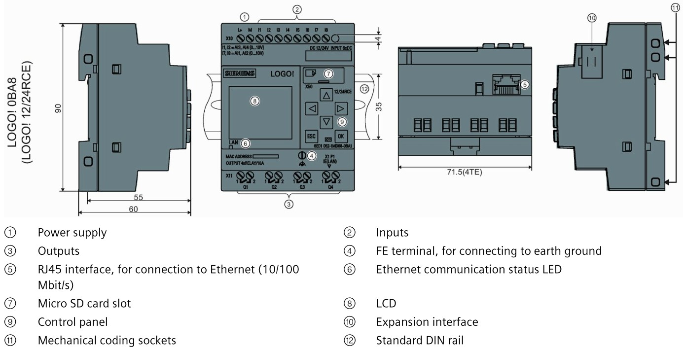
So, we first need to cover what a PLC (Programmable Logic Controller) is… A PLC has a MCU inside but it was developed for a more hostile environment (industrial). PLC tend to be extremely expensive (around 10K USD Dollars) and the needed software to program them is not free nor opensource like its counterpart (Arduino Boards). Do to this normally to see interact with one you would have needed to work in a place that could afford this hardware and software. SIEMENS changed the game by developing a small PLC that is in a more accessible cost range and named it LOGO!.
Week 4
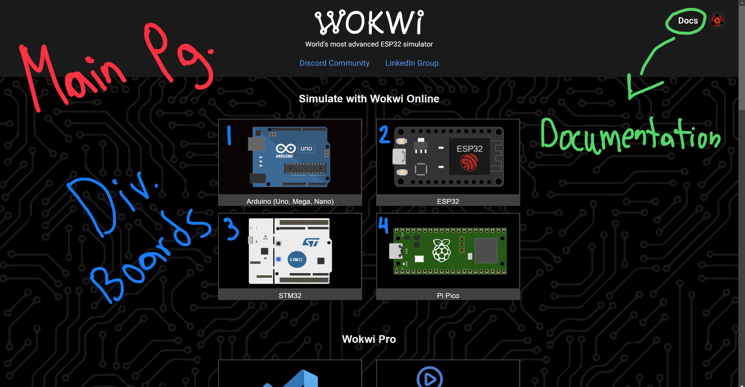
WOKWI is an inline simulator that lets you test code and hardware in a virtual space. Being able to test a specific developer board with a list of hardware can greatly impacted the process of jumping to designing your own PCB. Quick disclaimer… I’ll be using the 5V pin of the MEGA because WOKWI doesn’t have a DC power supply. When dealing with servo motors it’s better to give them a separate power source because they add a lot of noise to the circuit. Just remember to have a common GROUND. Otherwise, the circuited won’t work properly.
When you go to the WOKWI website you’ll be greeted with the main page that lets you select the development board you want to work with. I use an Arduino MEGA to simulate the code ill be using with part of my final project. Pleas watch the following video before you keep reading.
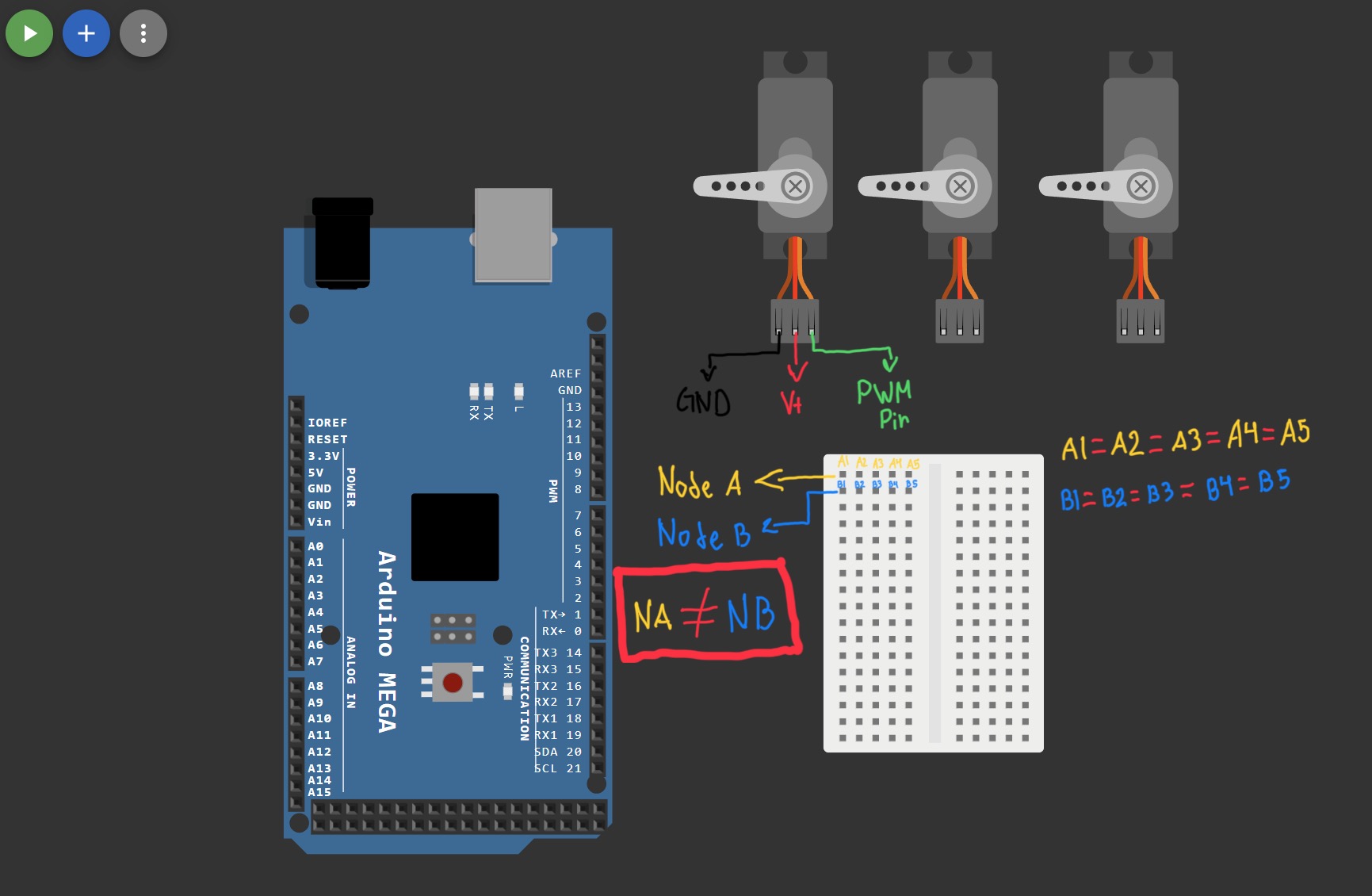
In the video you’ll see that I added in the hardware section 3 servo motors and a breadboard. My final project is a box with 3 compartments. Each compartment will have a door that will be opened with the servo motors (1 servo per door). The breadboard come into play when I need to connect wires in the same Arduino pins. In this particular case the servos need to share the seme 5V and GND (ground) pin. The PWM (Pulse Width Modulation) pin needs to be different because the servos are moving at different times and coordinates. If the 3 servers move at the same time and coordinate then they can share the same PWM pin.
Now we need to understand a little of the wiring of the servo motor… Servos have 3 wires (V+, GND and PWM). Please check the following pictures to identify the location of the wires. Servos share 2 wires and if you observe the pint of the Arduino MEGA there is only one V+, three GND’s and multiply PWM. Smaller developer boards tend to only have one GND. Now the breadboard comes into play. If you put the breadboard like in the picture It would be easier to understand how they work. Each row is what we call a node and in simple words it’s a pin that you can access in 5 different positions (Ex. A1, A2, A3, A4 and A5). Jumping to a different row takes us to a different node.
Please observe the following picture before reading what comes next. If you observe the hardware schematic you can see 3 colored wires (RED= V+, BLACK= GND and GREEN= PWM) that represent V+, GND and PWM. As mentioned before V+ and GND will need more space to connect multiple wires in the same pin or node. Please observe that the final step to officially merge every wire to the same node you need to connect the 5V and the GND pins of the Arduino to the V+ node and the GND node on the breadboard. The PWM wires go directly to the corresponding pins (PWM).
If you have any kind of experience coding in the Arduino IDE then you’ll defiantly feel at home. There is only one extra step that is related to the libraries you declare in the code. There is one extra step that you need to do. Please see the following video .
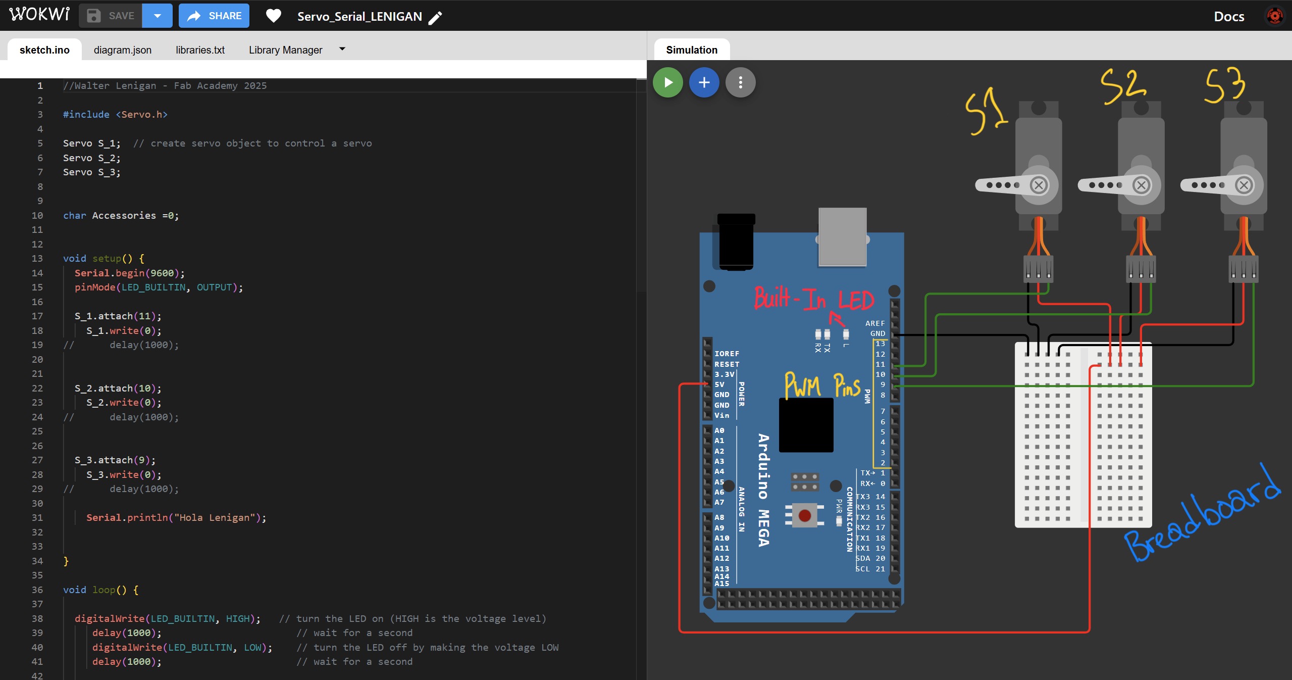
If you saw the video then you’ll noticed that WOKWI has a tab named “Library Manager”. In this tab you must upload or select the libraries that are declared in the code. In my case it’s the Arduino Servo library. Now lets talk about the code... The following code will drive my Final Project.
//Walter Lenigan - Fab Academy 2025

#include <Servo.h>

Servo S_1;  // create servo object to control a servo
Servo S_2;
Servo S_3;


char Accessories =0;


void setup() {
  Serial.begin(9600);
  pinMode(LED_BUILTIN, OUTPUT);

  S_1.attach(11);
    S_1.write(0);
//    delay(1000);


  S_2.attach(10);
    S_2.write(0);
//    delay(1000);


  S_3.attach(9);
    S_3.write(0);
//    delay(1000);

    Serial.println("Hola Lenigan");


}

void loop() {

  digitalWrite(LED_BUILTIN, HIGH);   // turn the LED on (HIGH is the voltage level)
      delay(1000);             // wait for a second
      digitalWrite(LED_BUILTIN, LOW);    // turn the LED off by making the voltage LOW
      delay(1000);             // wait for a second

  if (Serial.available() > 0) {     // It will only send data when the received data is greater than 0.
    Accessories = Serial.read();
switch (Accessories) {
    case '1':
      S_1.write(63);
      S_2.write(0);
      S_3.write(0);
      Serial.println("Servo #1 Open");
        break;

    case '2':
      S_2.write(59);
      S_1.write(0);
      S_3.write(0);
      Serial.println("Servo #2 Open");
        break;

    case 'C':
      S_3.write(65);
      S_1.write(0);
      S_2.write(0);
      Serial.println("Servo #3 Open");
        break;

    case '8':
      S_1.write(0);
      S_2.write(0);
      S_3.write(0);
      Serial.println("Servos to ORIGIN");
        break;        }


  }
}
The code uses 3 objects (S_1, S_2 and S_3) that will be used to control three separate servo motor in specific moments. Through the serial port the code is in stan-by waiting to receive characters '1' (moves Servo_1), '2' (moves Servo_2), 'C' (moves Servo_3), or '8' (moves all servos to initial position). Only 1 servo will be active at a time so if you send the characters in sequence one servo will move to the defined position and the previous one will move back to initial position. After sending the character the code will send a response message with a serial print indicating the servo that moved and the built-in led will be blinking for no specific reason hehe. Now please see the following video