
Week 2 (Computer-Aided Design)
Week 2
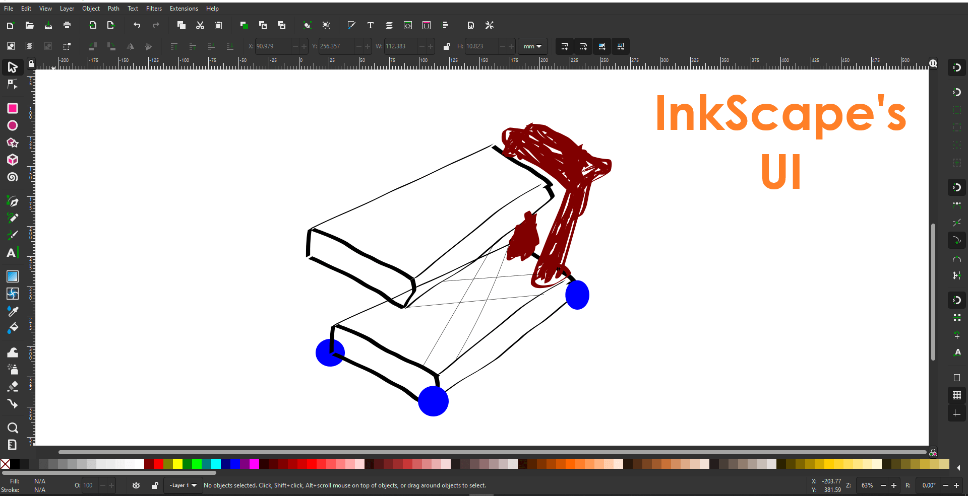
I tend to have many problems using software like InkScape to design something in 2D because it basically gives you a free world without any kind of constraints. I’ll try to make a drawing that represents a possible final project. This could probably be a scissor lifter. I can barely draw with a real pen and paper so I didn’t have a lot of expectation trying to draw in InkScape. I manage to discover that no matter what kind of line you make you can always see the nodes and change them afterwards. I don’t know if it’s possible in InkScape but I can’t add relationships to the lines. Like making them parallel or perpendicular to each other.
The UI has many options to control colors. layers, brightness, etc... You don’t really have a good reference on where to draw. I decided to use the effect of using a paint brush and tried to use a smoothing tool to make the lines straighter. I tried using the lines tool but I didn’t like because it gave a hard time trying to connect the nodes. To make the boxes drawed one and copy/paste the vectors to give a more symmetrical look.
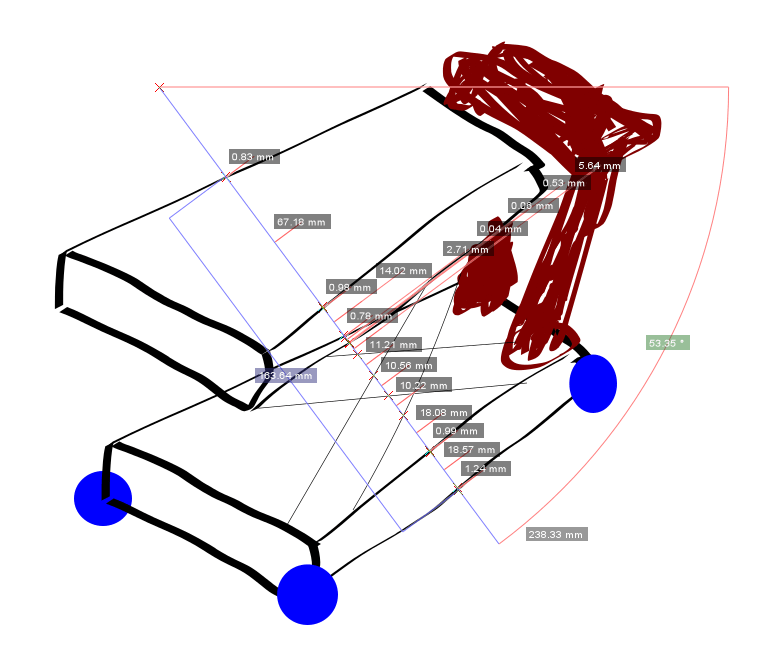
After doing this normally I like to give parameterize the sketch by adding measurements and constraints to the vectors. Doing this in InkScape is really tedious. The measuring tool is extremely bad. I can’t measure a line from point A to B. T measure I have to activate the tool my pressing the letter “M” on my keyboard and left click with the mouse to make a line pop and create a semicircle with irrelevant information. If you want a measurement you need to make sure the measuring tool line is touching more than one point. Also make sure the line is on a predetermined angle (15°, 30°, 45°, etc.) by pressing “CTRL”.
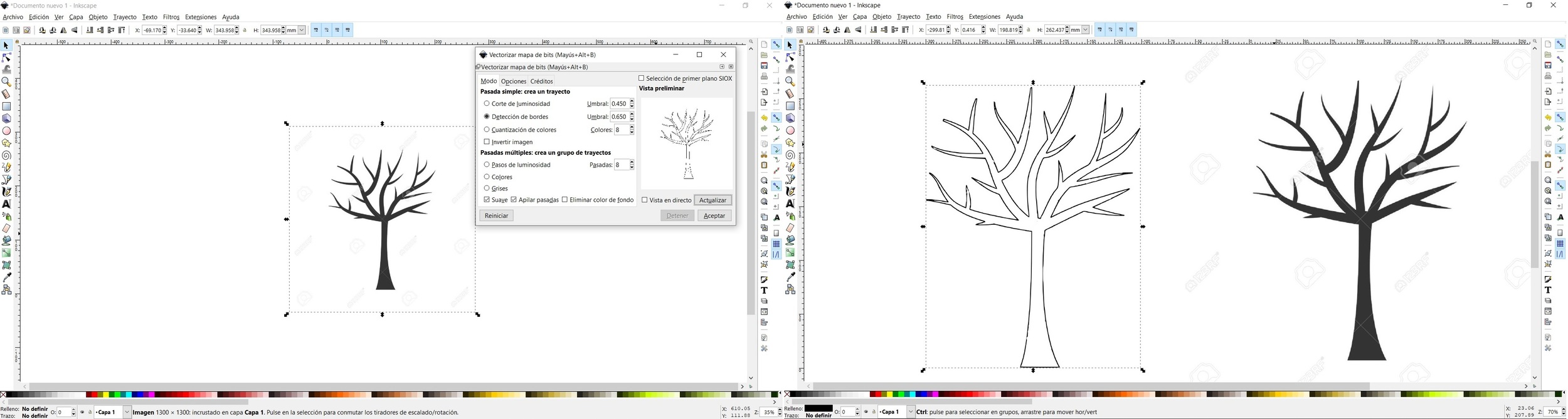
In conclusion, InkScape is not designed to make vectors and take them to a CAD software to make them 3D. The perfect use InkScape has for me is to vectorize an image, export them in DXF format and use them on a CAD software like SolidWorks to make the transition from 2D to 3D or on a CAM software and use the vectors as traces for a CNC. Maybe for a PCB milling. My friend Adrian Torres has a picture of this process.
Now in SolidWorks we have a different story. In this software to give a little more detail to the final structure I made subparts. This helps give you a better idea on the manufacturing process you are going to eventually determine. In SolidWorks you have 2D and 3D sketches. In the next picture you can see how the 3D sketch looks like. This type of sketch gives me complete access to the 3D space and gives me the freedom of adding different types of constraints to lock a sketch in a specific location and add measurements.
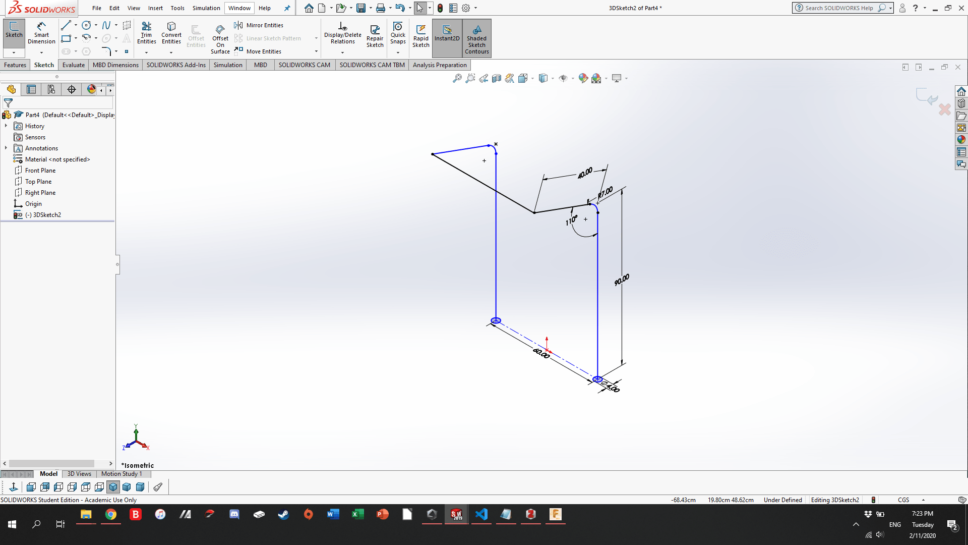
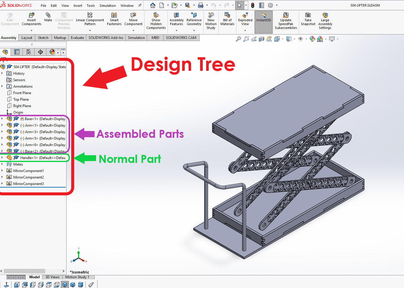
After making the sketches you can use different extrusion methods to make a line a cylinder or a square into a cube. Repeating this process will give you the final part. Making a 3D part is not restricted to one method. It’s not like following a recipe. Every designer has a different way of imagining the way to make a shape. CAD software have a version of design tree. By looking at the design tree you can get a lot of information like: the face I started a sketch, origin of the 3D space or part, number of bodies, if it’s a part or assembled part, etc... I my design I used many assembled parts to create the final structure.
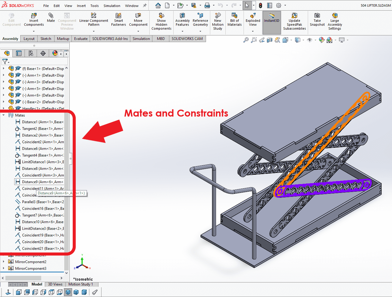
On the next picture you can see on the design tree the dropdown menu of the “mates” section. In this dropdown menu con can see a detailed description on the mates and constraints I’ve places. If you place the mouse on one of the mates SolidWorks highlights the parts involved in the selected mate. You have free will on how to mate things in SolidWorks. After the picture you’re able to interact with some of the parts I made. This is the only reason why I use the Fusion 360 cloud system, because its able to generate HTML5 automatically giving you that special UI where you can play around with a part, disassemble it and even measure it. For best interaction with the parts use the EDGE browser.
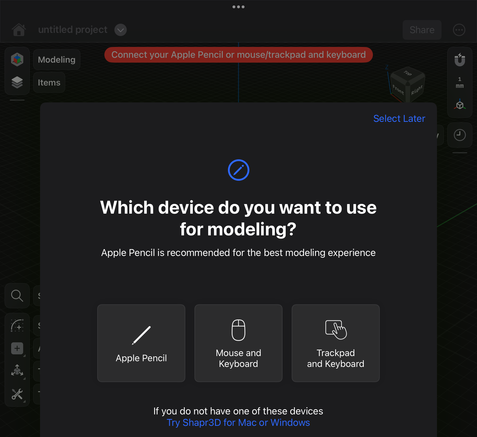
Shapr3D is a CAD software that runs in MAC, windows and iPad OS devices. Unlike OnShape, Shapr3D runs locally and it requires an iPad with the M series ship. I’m using an iPad pro with the M2 chip. To navigate the UI you can a mouse/trackpad and keyboard but in mu opinion the 3rd option it’s a game changer. I’ll be using the Apple Pencil.
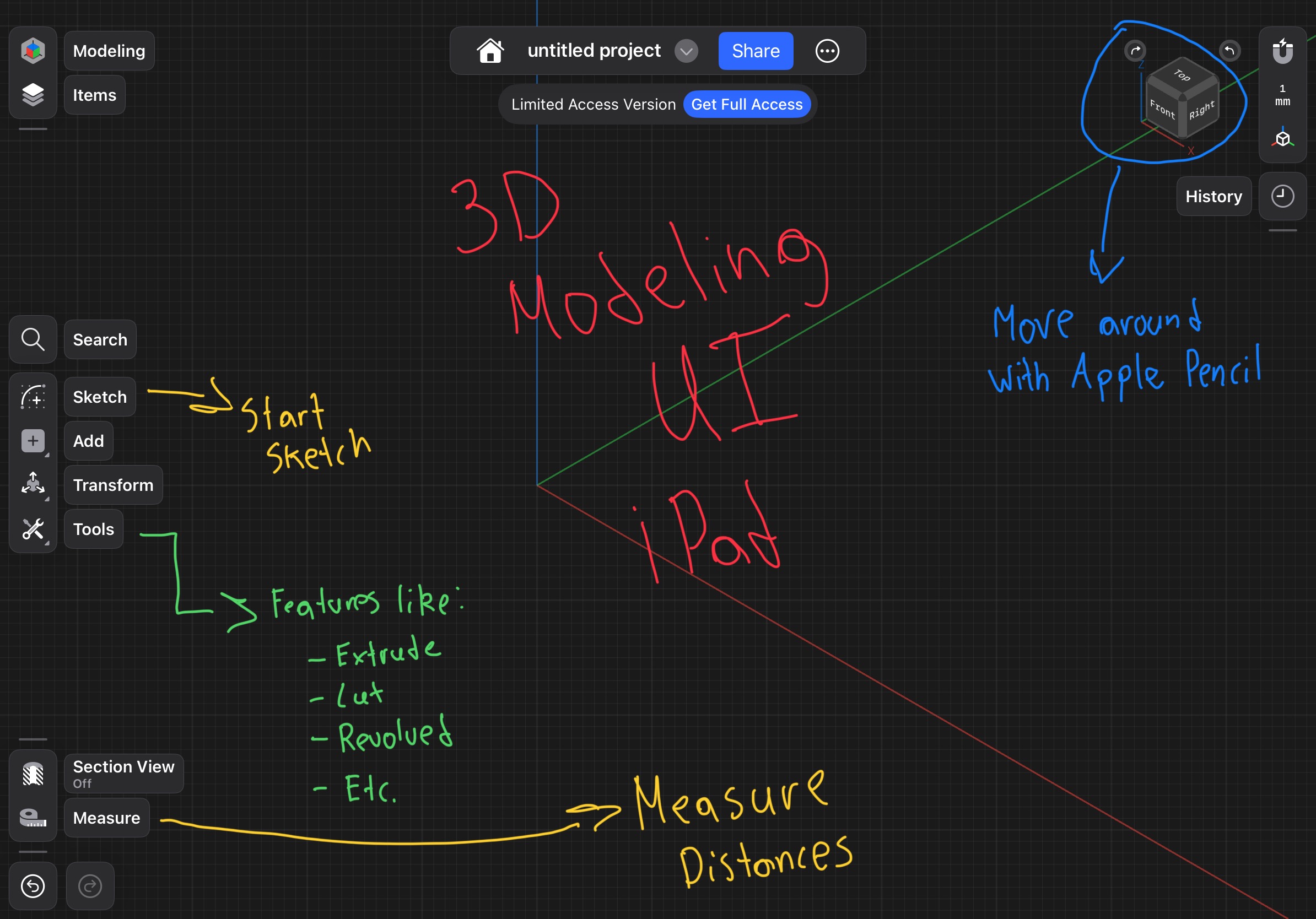
The following video shows how the UI looks and feels. Remember that I’m using and Apple Pencil so things change a little on the way you interacted with the UI. If you want to zoom you use a 2-finger gestor and if you want to move around you only use 1 finger.
The following video you can see how some of the basic gestors you can do with your apple pencil to draw a line, circle and arc. Please observe how the UI changes so that a different set of tool bars appear that are equipped with drawing tools. The software also gives you video suggestion to help you draw.
The following video You can see how a draw a sphere using finger gestors and the apple pencil. Like in SolidWorks I select a plane to draw on and I use the apple pencil gestors to draw the line and arc. After that I leave the sketch so the special features list is visible (tools button). I used revolve to make the arc spin on the axis we previously draw. to have a better perception of the gestor with the apple penc please see this YouTube Video
Another cool thing that SolidWorks has is an integrated segment for simulations of many kinds (heat dissipation aerodynamics, heat dissipation friction, etc.) that help see how a part will react to specific condition. I made an example that simulates the motion of a gearbox that reduces speed and adds torque.
Make (Almost) Anything