group assignment:
compare the performance and development
workflows for other architectures
https://fabacademy.org/2022/labs/ciudadmexico/embedded-programming.html
individual assignment:
read a microcontroller data sheet
program your board to do something,
with as many different programming languages
and programming environments as possible
For this assignment I will use the card that was designed in electronic design to program it and turn on the LED by pressing the button both contained on the PCB
Review the Data sheet there is a lot of interesting information and I think it is important to highlight the following basic information to know the Atmel SAM 11C microcontroller that we use in the designed card


The information in these two images is basic to know firstly the meaning of the acronym of the microcontroller and the second image to know the use of the pins to connect the other devices or components in the best or most correct way.

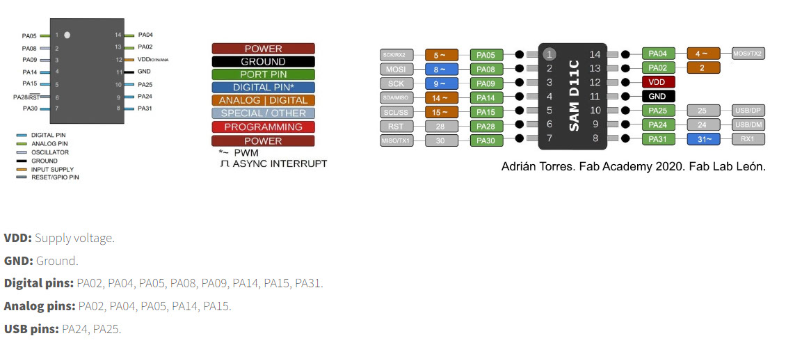
The pins of the Arduino IDE, to know the correspondence to connect according to the analog or digital inputs/outputs.
Button
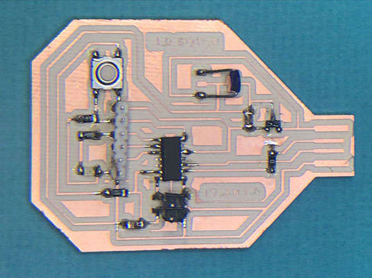
Resistor 499.0 OHMS
Capacitor 10 uF
Regulador 3.3 -0.1 A
LED Red
AT SAMD IIC
Header
Resistor 0 OHMS
Resistor 10k OHMS
Bridge
Capacitor 10 uF
Programmable header for our card
Once the pcb is ready with all the components, we program it with the help of another board and the Command Prompt program (Símbolo del sistema)
We locate in our system the EDBG folder
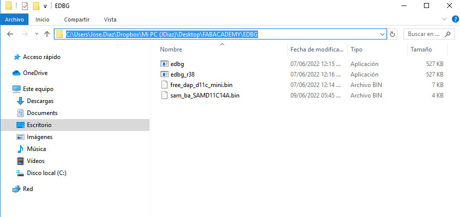
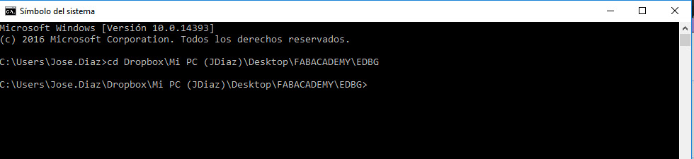
We change directory using cd space and then paste the address of the folder:
Dropbox\Mi PC (JDiaz)\Desktop\FABACADEMY\EDBG
We add the code we got from Adrian Torres' page at FAbLab Leon:
https://fabacademy.org/2020/labs/leon/students/adrian-torres/samdino.html#swd
Comando: edbg -ebpv -t samd11 -f sam_ba_SAMD11C14A.bin
NOTE: edbg It has to be the name of the program as it is in the folder (*.exe)
C:\Users\Jose.Diaz\Dropbox\Mi PC (JDiaz)\Desktop\FABACADEMY\EDBG>edbg -ebpv -t samd11 -f sam_ba_SAMD11C14A.bin
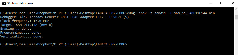
And everything is correct both programming and verification
Since the card is ready to be programmed, we use the Arduino software and load the following code to program the card that turns on the LED by pressing the button included on the PCB
Original Code
//Fab Academy 2020 - Fab Lab León
//Button + LED
//SAMDino
//SAMD11C
//
//Original code:Neil Gershenfeld 12/8/19
// This work may be reproduced, modified, distributed,
// performed, and displayed for any purpose, but must
// acknowledge this project. Copyright is retained and
// must be preserved. The work is provided as is; no
// warranty is provided, and users accept all liability.
//
const int ledPin1 = 5;//first light
const int buttonPin = 4;// button pin
int buttonState = 0;//initial state of the button
int i = 0; //variable intensity led
void setup() { //declaration of inputs and outputs
pinMode(ledPin1, OUTPUT);
pinMode(buttonPin, INPUT);
}
void loop() {
buttonState = digitalRead(buttonPin);// we read the state of the button
if (buttonState == HIGH) { //if we press the button
digitalWrite(ledPin1, HIGH);
delay(500);
digitalWrite(ledPin1, LOW);
delay(500);
digitalWrite(ledPin1, HIGH);
delay(500);
digitalWrite(ledPin1, LOW);
delay(500);
digitalWrite(ledPin1, HIGH);
delay(2000);
digitalWrite(ledPin1, LOW);
delay(1000);
}
else { //if we don't press the button
digitalWrite(ledPin1, LOW);
}
}
Modified Code
//Fab Academy 2020 - Fab Lab León
//Button + LED
//SAMDino
//SAMD11C
//
//Original code:Neil Gershenfeld 12/8/19
// This work may be reproduced, modified, distributed,
// performed, and displayed for any purpose, but must
// acknowledge this project. Copyright is retained and
// must be preserved. The work is provided as is; no
// warranty is provided, and users accept all liability.
//
const int ledPin1 = 5;//first light
const int buttonPin = 4;// button pin
int buttonState = 0;//initial state of the button
int veces = 2; //variable
void setup() { //declaration of inputs and outputs
pinMode(ledPin1, OUTPUT);
pinMode(buttonPin, INPUT);
}
void loop() {
buttonState = digitalRead(buttonPin);// we read the state of the button
if (buttonState == HIGH) { //if we press the button
secuencia(veces); //function is called
veces++;
}
else { //if we don't press the button
digitalWrite(ledPin1, LOW);
}
if(veces>5){ //conditional statement
veces=2;
}
}
//function
void secuencia(int v) {
for (int i = 0; i < v; i++) { //for loop
digitalWrite(ledPin1, HIGH);
delay(500);
digitalWrite(ledPin1, LOW);
delay(500);
}
}
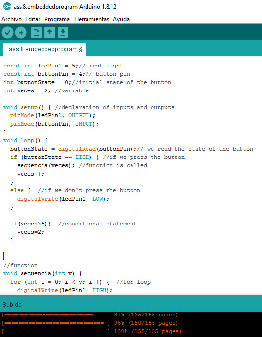

Taking the original code as a base, the new code was modified using a sequence called "veces", where the button is pressed once and the LED flashes twice, the button is pressed again and it flashes three times, and the button is pressed again and it flashes four times. times and once more the button is pressed and it flashes five times and finally the button is pressed again and it flashes twice again, thus starting the sequence.