group assignment:
Use the test equipment in your lab to observe the operation
of a microcontroller circuit board
https://fabacademy.org/2022/labs/ciudadmexico/cdmx_electronics-design.html
individual assignment:
redraw an echo hello-world board,
add (at least) a button and LED (with current-limiting resistor)
check the design rules, make it, and test that it can communicate
extra credit: simulate its operation
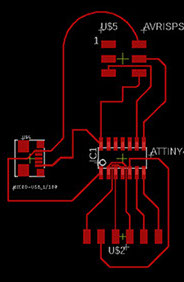
For this assignment I decided to redesign the plate I made based on the samdino (https://fabacademy.org/2020/labs/leon/students/adrian-torres/samdino.html) and name it josanino. I added a led and a button
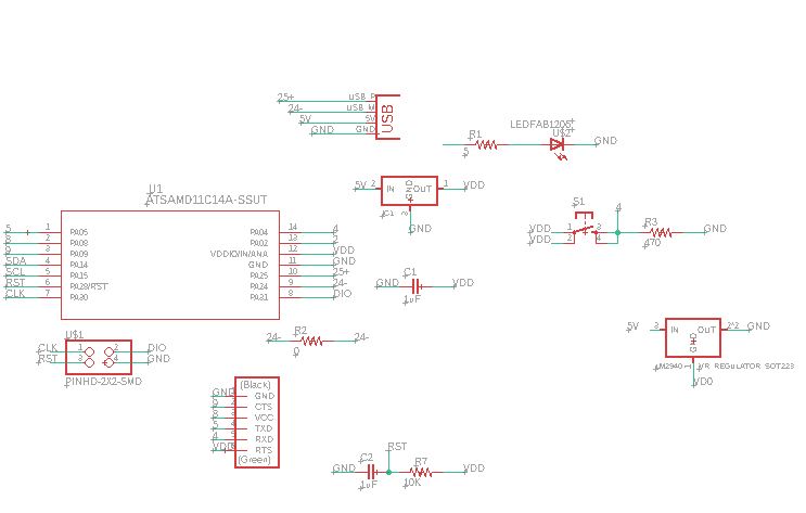
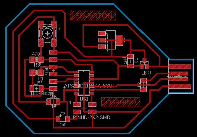
The schematic and the board are made in the eagle software based on the board I made from JOSANINO and a led spotlight and a button were added
button
LED
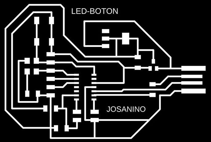
We export from eagle the image with .PNG format and in monochrome at 1200 dpi and with the window option where the origin 0,0 will be the lower left corner

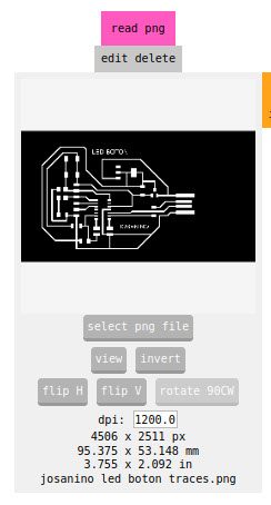
We export from eagle the image with .PNG format and in monochrome at 1200 dpi and with the window option where the origin 0,0 will be the lower left corner. We open it in the mods software
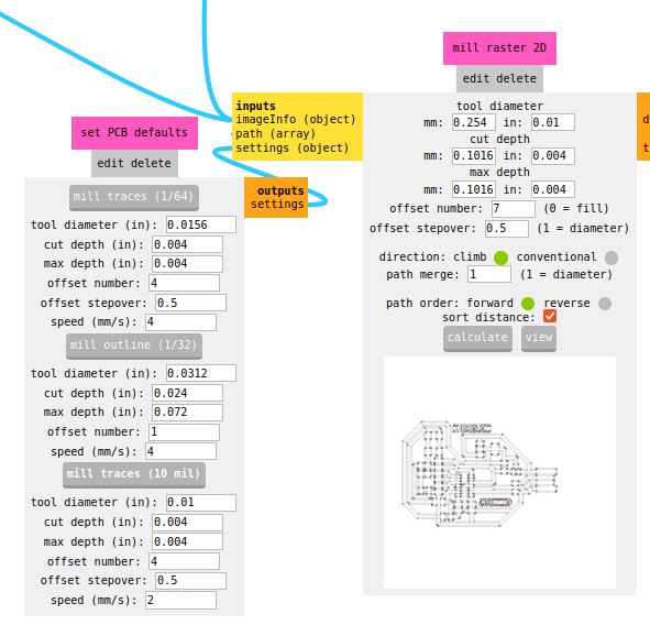
We select the mill traces button (1/64) to assign the cutter that will trace the tracks, we also assign the number 4 to the offset and the speed also in 4 so that the traces are milled without breaking.
Later we press the calculate button so that the machine calculates the route to be made on the copper plate of our PCB
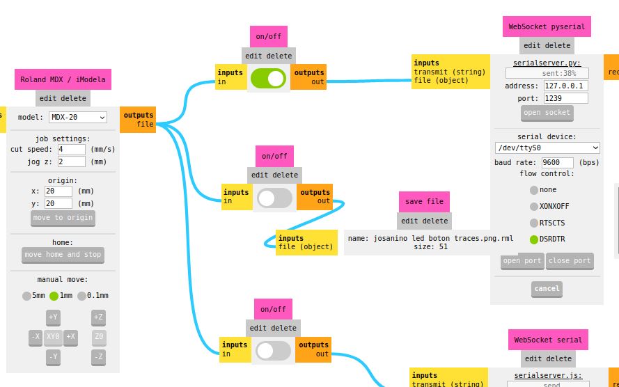
We verify that the MDX 20 model machine is selected and we assign the origin right at the corner of our plate placed on the machine, which in this case was the coordinate x=20 y=20. We turn on the first button and press the open port button so that the machine makes the correct connection to machine the PCB board.
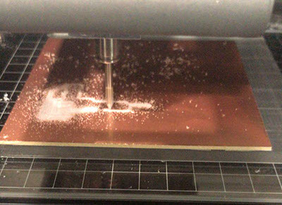
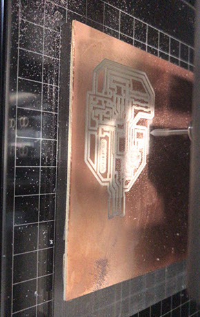
Plate milling and final finishing
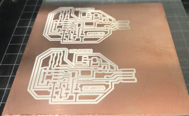
Once our plate is cut, all the overlapping components are presented to verify that no component is missing and start welding

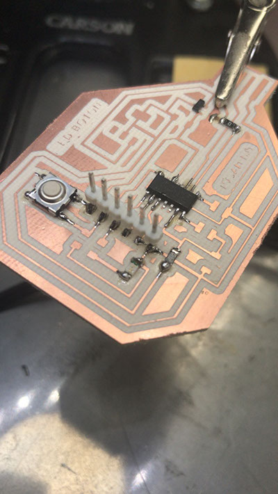
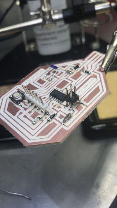


Board ready and with all the components already soldered
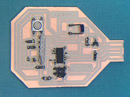
Resistor 499.0 OHMS
Capacitor 10 uF
Regulador 3.3 -0.1 A
LED Red
AT SAMD IIC
Header
Button
Resistor 0 OHMS
Resistor 10k OHMS
Jumper
Note: Due to the fact that the 5V regulators in the fablab stock were finished, I had to use a Jumper to be able to feed the 5v output of the PC and make the continuity simulating the regulator
Capacitor 10 uF
Programmable header for our card
Once the pcb is ready with all the components, we program it with the help of another board and the Command Prompt program (Símbolo del sistema)
We locate in our system the EDBG folder
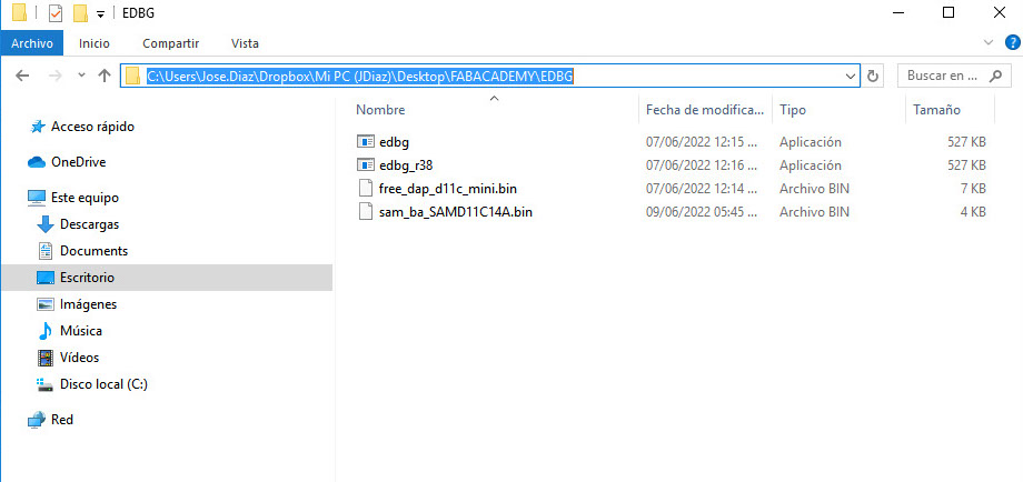
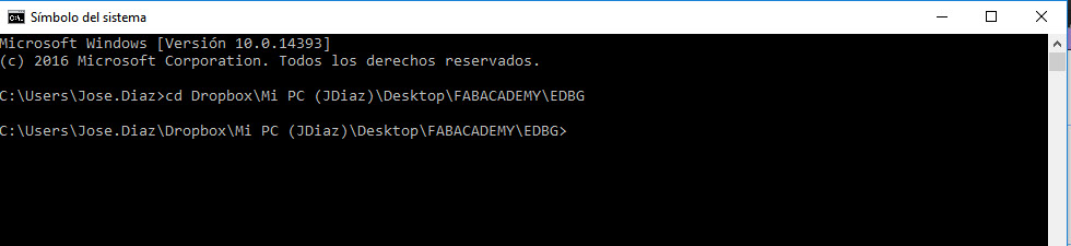
We change directory using cd space and then paste the address of the folder:
Dropbox\Mi PC (JDiaz)\Desktop\FABACADEMY\EDBG
We add the code we got from Adrian Torres' page at FAbLab Leon:
https://fabacademy.org/2020/labs/leon/students/adrian-torres/samdino.html#swd
Comando: edbg -ebpv -t samd11 -f sam_ba_SAMD11C14A.bin
NOTE: edbg It has to be the name of the program as it is in the folder (*.exe)
C:\Users\Jose.Diaz\Dropbox\Mi PC (JDiaz)\Desktop\FABACADEMY\EDBG>edbg -ebpv -t samd11 -f sam_ba_SAMD11C14A.bin
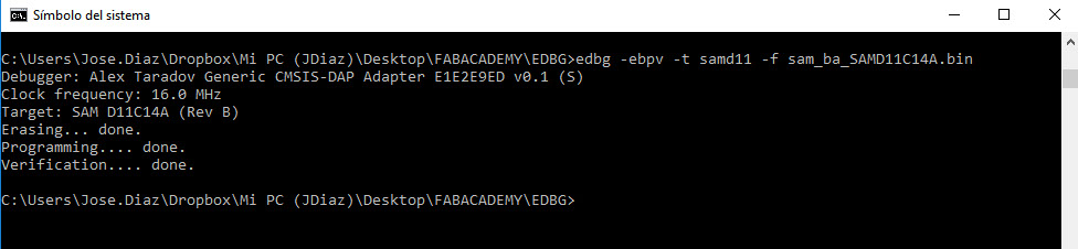
And everything is correct both programming and verification
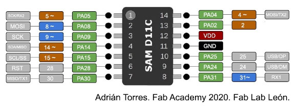
With the help of this scheme by Adrian Torres, we identify and confirm the pin where our LED is connected, which this time is Pin5
Programming is done, we verify it, upload it and execute
int LED = 5;
void setup() {
pinMode (LED,OUTPUT);
}
void loop() {
digitalWrite (LED,HIGH);
delay(1000);
digitalWrite (LED,LOW);
delay(2000);
}