A1
Project Management
My final project is an experiment with responsive light through sensors to create an active lamp.
This idea, a constant evolutonary process, relies on the procedure of having a series of little led lights attached to a simple hexagonal frame that allows them to response at human approach, creating an set of movements and emotions.
Tracking progress:
1.- what tasks have been completed, and what tasks remain?
2.- what's working? what's not?
3.- what questions need to be resolved?
4.- what will happen when?
5.- what have you learned?
Design process...
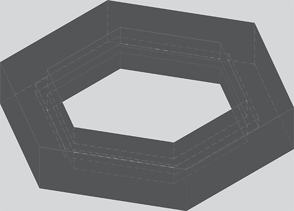
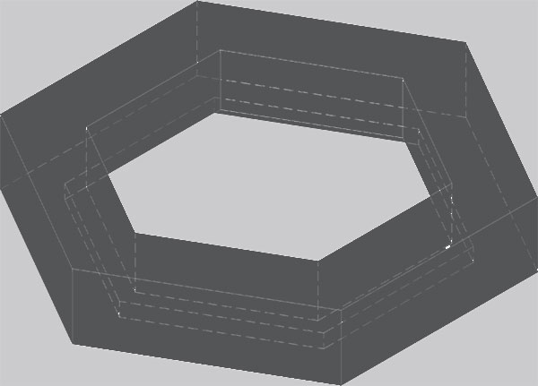
Take the form, the main concept
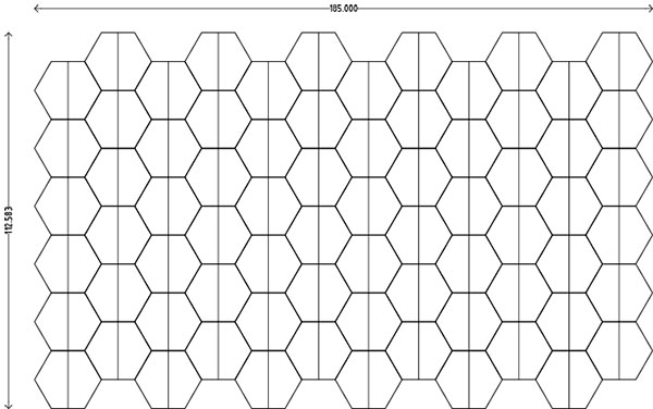
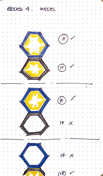
This sketch is based on a little research using hexagons, to have a bee-hive structure inside two planes.
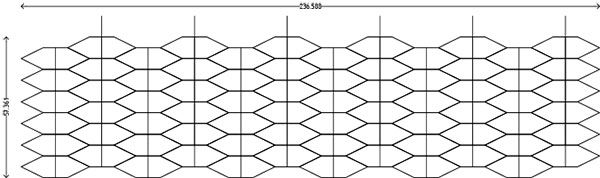
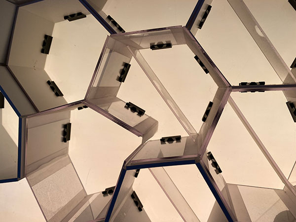
The original idea, interlocking parts
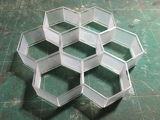
The original idea, within two panes.
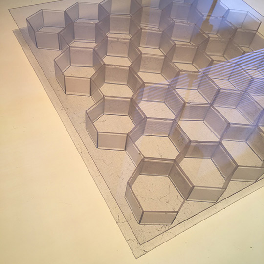
The original idea, as a reflectivity surface...
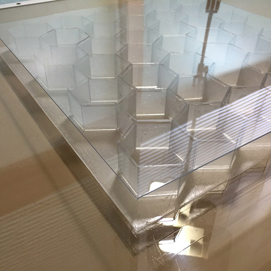
or a simple wall that can be folded or collapsed.
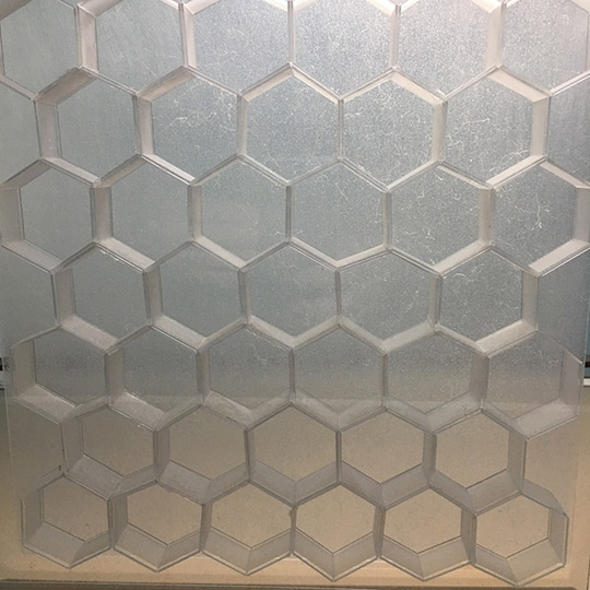
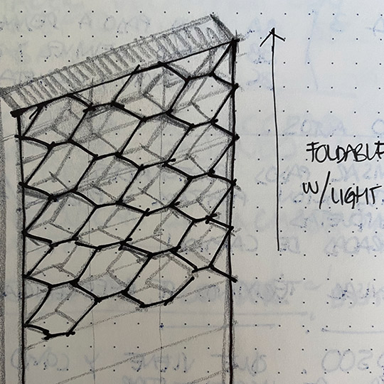
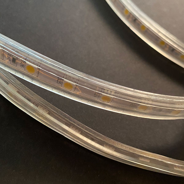
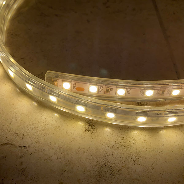
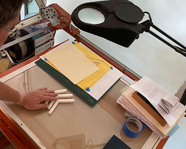
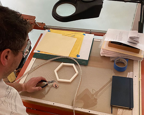
The prototype using a led strip to see how it works
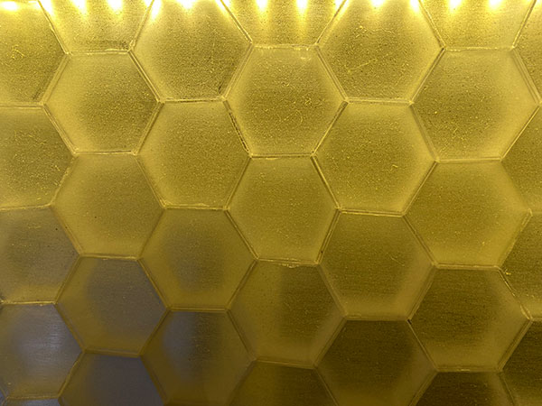
An old prototype using backlight and seeing the joints if it might work as a foldable structure, with some errors.
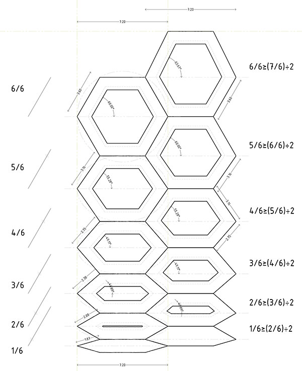
Further development in A11
Some final drawings applied to the week 10 assingment, having proper distances for production.

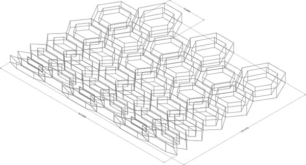
So, the modular base, is a hexagon of 7.2 cms hat could be scaled up to 4 times, to have a 28cms piece.
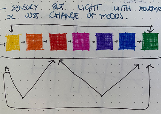
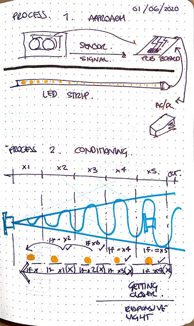
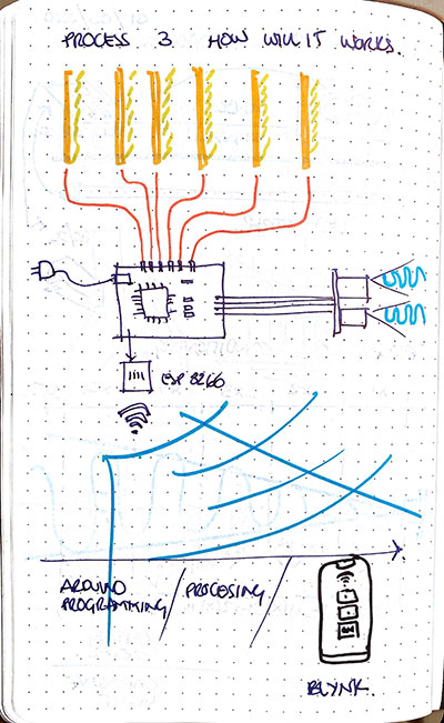
How i want this product work... the basics is the following light through a distance sensor or infrared sensor.
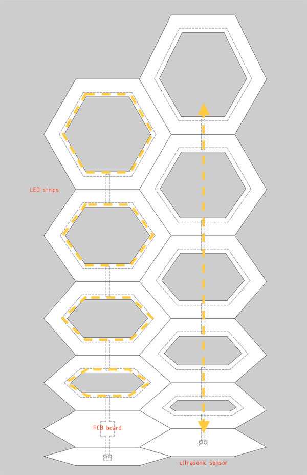
This is the graphic idea of the process
Impact of the idea A14
PCB development:
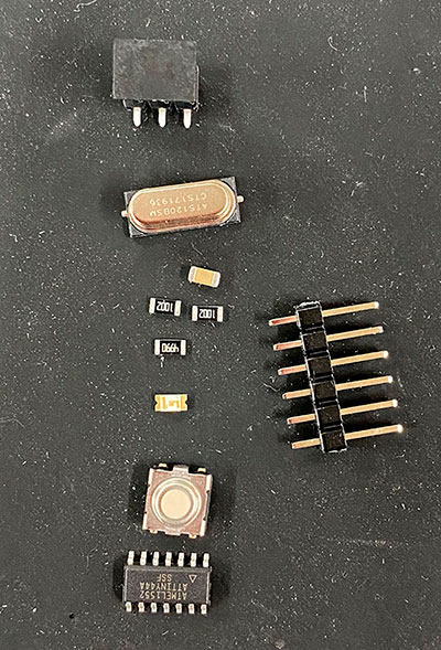
Some components to be used:
ATtiny processor
& pin connector
Crystal regulator
Diode 100
Ans LED strip
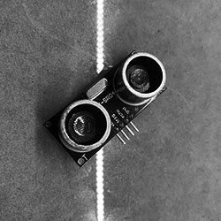
Ultrasonic sensor
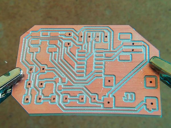
This is the PCB board that i'm starting to use... of course, i have to match the programming with it, but this is versión 2.
A Attiny 44 basic connection to load vlean 12v energy to the led strip and a ultrasonic sensor for the output device approach
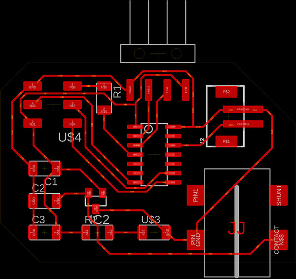
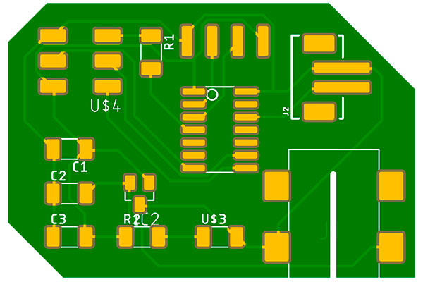
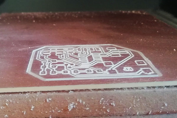
Tha final version 2 PCB to be sent to milling....
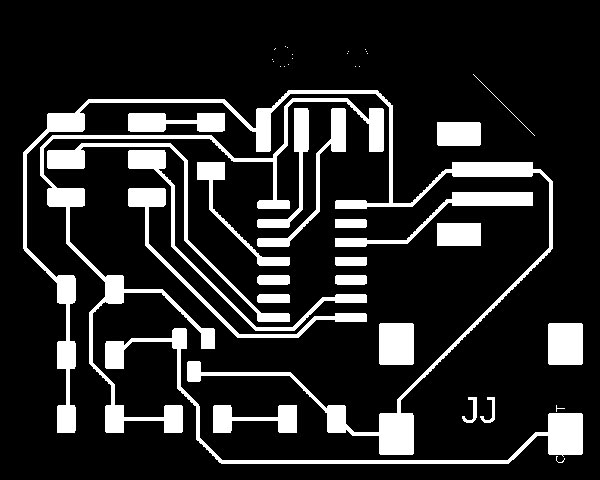
Milling process, considering a 10mil engrave separation to avoid cluttering... however, i had to run the piece twice.

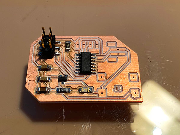
The components assambled all together, form the hexagon based piece, using the base or smaller parts as those to hid the electronic components as well as sensors, having all connections from the back of the molded piece, and integrating all parts as a whole.
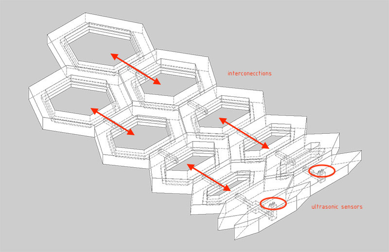
Thus, there be a chance to have a larger lamp or just a set of smaller ones, depending of the programable PCB
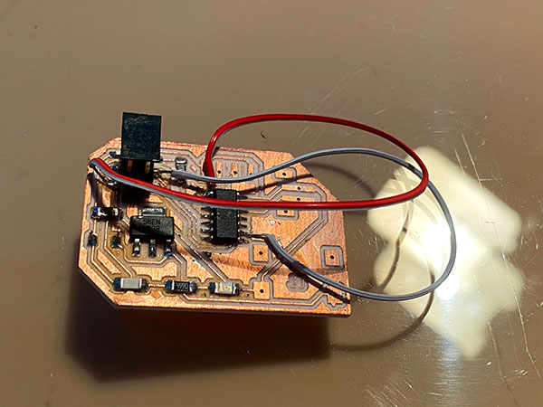
Currently, i'm working on the final PCB board and how to program it, with this CODE, but the main idea is almost finished.
# define led 13
int trigger = 9;
int echo = 10;
float tiempo_de_espera,distancia; // floating distance.
void setup() {
Serial.begin (9600); // serial communication
pinMode (trigger, OUTPUT); // pin 9 as exit
pinMode (echo, INPUT); // pin 10 as entrance
pinMode(2,OUTPUT);
pinMode(3,OUTPUT);
pinMode(4,OUTPUT);
pinMode(5,OUTPUT);
pinMode(6,OUTPUT);
pinMode(7,OUTPUT);
}
void loop() {
digitalWrite (trigger,LOW); // set low pin 10 for 2 microseconds
delayMicroseconds(2);
digitalWrite (trigger, HIGH);// set high pin 10 for 10 microseconds;
delayMicroseconds (10); // sonar for 10 seconds
digitalWrite (trigger, LOW); // set low again pin 8
tiempo_de_espera = pulseIn (echo,HIGH); // pulseIn, recoge la señal del sonido que emite el trigger
distancia =(tiempo_de_espera/2)/29.15; // formula para hallar la distancia
Serial.print (distancia); // print distance in cm
Serial.println ("cm");
delay (700);
if (distancia>=28 && distancia <=100){
digitalWrite (2,0);
digitalWrite (3,0);
digitalWrite (4,0);
digitalWrite (5,0);
digitalWrite (6,0);
digitalWrite (7,0);
}
if (distancia>=24 && distancia <=28){
digitalWrite (2,1);
digitalWrite (3,0);
digitalWrite (4,0);
digitalWrite (5,0);
digitalWrite (6,0);
digitalWrite (7,0);
}
if (distancia>=20 && distancia <=24){
digitalWrite (2,1);
digitalWrite (3,1);
digitalWrite (4,0);
digitalWrite (5,0);
digitalWrite (6,0);
digitalWrite (7,0);
}if (distancia>=16 && distancia <=20){
digitalWrite (2,0);
digitalWrite (3,1);
digitalWrite (4,1);
digitalWrite (5,0);
digitalWrite (6,0);
digitalWrite (7,0);
}
if (distancia>=12 && distancia <=16){
digitalWrite (2,0);
digitalWrite (3,0);
digitalWrite (4,1);
digitalWrite (5,1);
digitalWrite (6,0);
digitalWrite (7,0);
}
if (distancia>=8 && distancia <=12){
digitalWrite (2,0);
digitalWrite (3,0);
digitalWrite (4,0);
digitalWrite (5,1);
digitalWrite (6,1);
digitalWrite (7,0);
}
if (distancia>=4 && distancia <=8){
digitalWrite (2,0);
digitalWrite (3,0);
digitalWrite (4,0);
digitalWrite (5,0);
digitalWrite (6,1);
digitalWrite (7,1);
}
}
Testing the code
Complementary graphic idea of colors following a gradient
Trying to use a proximity sensor that make the wall sense the person and might change colors.